


- 全て
- NEWTOPのお客様事例
- NEWTOP エクスプローラー ハブ
- NEWTOP 業界の洞察
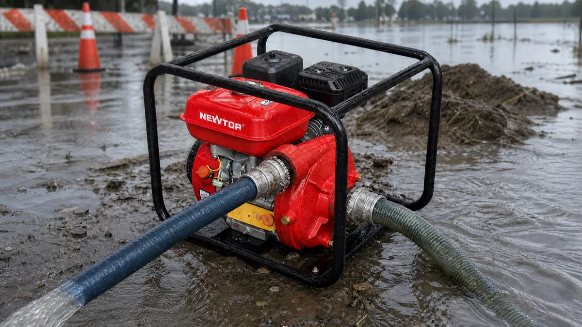
Choosing between a centrifugal pump and a self-priming ポンプ depends on your application, working environment, and customer needs. Centrifugal pumps provide higher efficiency and simple operation for stable water sources, while self-priming pumps offer easier startup and better flexibility for changing conditions.
販売代理店様向け, ディーラー, およびOEMバイヤー, selecting the right pump type is not only about technical performance but also about market demand, user experience, そして長期的な信頼性. A pump that works well in a fixed irrigation system may not be the best choice for construction sites or portable water transfer applications.
このガイドでは, we will compare centrifugal and self-priming ウォーターポンプ in terms of working principles, 効率, installation, メンテナンス, アプリケーション, and market suitability to help you make a better product selection decision.
What Is a Centrifugal Pump?
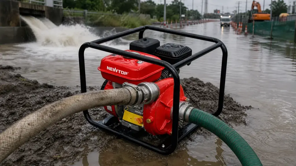
A centrifugal pump is the industry baseline for moving large volumes of water, converting mechanical motor power into hydraulic pressure using a rotating impeller and volute casing.
Core Definition and Energy Conversion
A centrifugal pump is one of the most common types of water pumps used for clean water transfer and irrigation applications. It uses centrifugal force generated by a rotating impeller to move water from the inlet to the outlet.
The mechanism works by increasing the velocity of an incompressible liquid, typically water. As the fast-moving fluid hits the casing walls, the system translates that raw kinetic velocity into usable pressure. Engineers treat this design as the baseline technology for moving large volumes of water against moderate pressure gradients because it delivers continuous flow without excessive mechanical complexity.
What Is a Self-Priming Pump?
A self-priming pump is a specialized centrifugal unit equipped with an internal reservoir to automatically evacuate air and restore liquid flow without repeated manual repriming.
A self-priming pump functions as a specialized centrifugal water machine engineered to evacuate air from its own casing and the connected suction line. Standard centrifugal pumps fail when air enters the system, forcing operators to manually re-prime them. The self-priming design addresses this primary limitation directly.
It incorporates an internal liquid reservoir that generates a vacuum on startup. This mechanism automatically draws water upward into the system before standard pumping begins. Because of this capability, engineers frequently specify these pumps for applications where the equipment must be installed above the water source.
Source High-Margin Garden Machinery Built to Last

How Does a Centrifugal Water Pump Work?
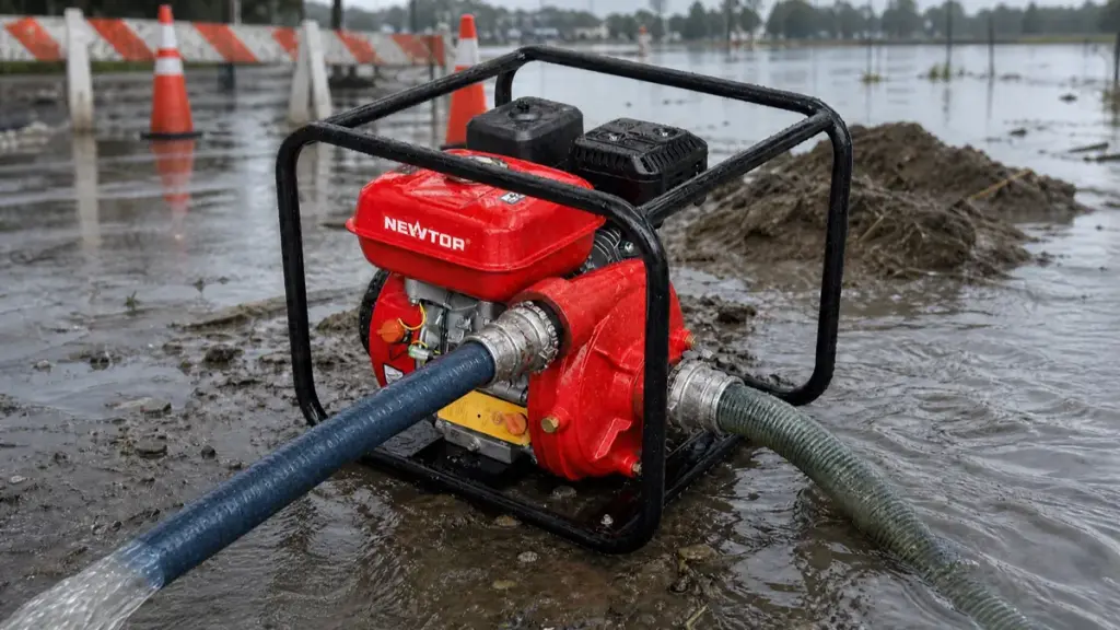
Centrifugal pumps rely on a spinning impeller to convert mechanical rotation into hydrodynamic pressure. They excel at high-volume water transfer but strictly require a fully primed casing before starting.
Core Energy Conversion Principle
At its foundation, a centrifugal pump relies on a straightforward energy exchange. An electric motor or diesel engine supplies rotational kinetic energy to the pump shaft. As the attached impeller spins, it transfers that mechanical energy directly to the incoming water, rapidly accelerating its velocity.
Once the water leaves the impeller blades at high speed, it slams into the surrounding casing. The casing acts as a conversion zone, forcing the high-velocity fluid to decelerate and transforming that kinetic energy into static pressure. This resulting pressure, or head, gives the water the force it needs to push through a piping network.
Key Internal Components
To understand the fluid dynamics, you need to look at the hardware doing the heavy lifting. Three primary components dictate pump performance:
- Impeller: A shaft-driven wheel equipped with curved blades. It uses centrifugal force to push water radially outward from the center.
- Casing (Volute or Diffuser): This stationary housing encloses the impeller. It features an expanding flow area designed to smoothly decelerate the water and build system pressure.
- Shaft and Motor: These elements supply the mechanical torque required for rotation. In standard water applications, the motor typically drives the shaft at speeds between 1750 そして 3500 回転数.
Step-by-Step Fluid Flow Process
The actual movement of fluid happens in a continuous, rapid sequence. Water first enters the pump axially through the suction port, flowing straight into the center—known as the eye—of the impeller. The spinning blades immediately capture this fluid and accelerate it radially outward toward the impeller’s outer edge.
This violent outward movement creates a critical low-pressure zone right at the impeller eye. Atmospheric and static pressure in the suction line react by continuously drawing more water into the pump to fill that void. その間, the original water hits the expanding wall of the volute casing, decelerates, and exits the discharge nozzle as a highly pressurized stream.
The Role of Initial Priming
Standard centrifugal water pumps share a strict operational constraint: they cannot pump air. Before you initiate startup, the casing and the entire suction line must hold a solid column of water. If air accumulates inside the casing, the impeller simply churns the gas. The unit becomes gas-bound and fails to generate the pressure differential required to move the fluid.
Because standard models lack built-in air evacuation features, they depend heavily on system design. Engineers typically install these units in flooded suction layouts, placing the pump below the water source so gravity maintains the prime. In situations where the pump sits above the water level, operators rely on external vacuum systems or foot valves to keep the system fully primed for the next cycle.
How Does a Self-Priming Water Pump Work?
Self-priming pumps mix retained water with incoming air, expel the air, and create a vacuum to draw liquid from below without manual repriming.
Initial Casing Fill and Seal Formation
Before you hit the power switch for the first time, you must manually fill the built-in reservoir with water. This crucial step prevents dry running, a condition that quickly overheats and destroys the mechanical seal. The retained water creates a hydrodynamic seal between the rotating impeller and the wear plate, establishing the physical conditions necessary for the initial suction action.
Air-Water Mixing at the Impeller
As the impeller starts spinning, it pulls in air from the non-flooded suction line. It aggressively mixes this incoming air with the water already sitting inside the casing directly at the impeller eye. This action forms a dense, pumpable air-water mixture, bypassing the typical air binding failure that stops standard centrifugal pumps.
Separation of Air and Recirculation of Water
The spinning impeller uses centrifugal force to fling the newly formed air-water mixture outward into the outer casing chamber. Inside this larger space, gravity and density take over. The lighter air rises to the top and escapes through an open discharge or a dedicated air-release device. The heavier water drops down and cycles back to the impeller through internal recirculation ports to repeat the mixing process.
Vacuum Creation and Suction Lift
Every time the pump expels a pocket of air, the total volume of air in the suction line drops. This continuous extraction creates a partial vacuum at the impeller eye and throughout the suction piping. With the pressure inside the pipe lowered, the higher atmospheric pressure resting on the below-grade water source pushes liquid straight up the pipe toward the pump inlet.
Transition to Standard Centrifugal Pumping
The priming cycle ends the moment the pump evacuates all the air and floods the entire flow path with water. From this point forward, the unit operates exactly like a conventional centrifugal pump, continuously converting water velocity into pressure for the system discharge. When you eventually shut the pump down, the integrated reservoir holds onto a specific volume of water, keeping the equipment ready for its next automatic prime.
遠心式ウォーターポンプと自吸式ウォーターポンプ: Key Differences at a Glance
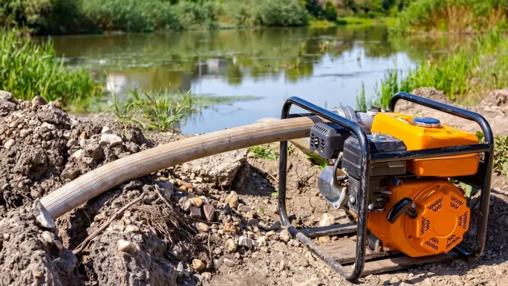
When evaluating a centrifugal vs self-priming water pump, the decision dictates your facility’s energy footprint and maintenance schedule. Engineers must balance peak hydraulic efficiency against the practical realities of air management and suction lift.
| 比較 | Centrifugal Pump | Self-Priming Pump |
|---|---|---|
| Priming requirement | Requires manual priming before operation | Automatically removes air after initial filling |
| Startup speed | Requires additional preparation before starting | Starts faster with less preparation |
| Efficiency | Slightly higher efficiency under ideal operating conditions | Slightly lower efficiency due to additional self-priming design features |
| インストール | Best suited for fixed installations with stable water sources | Better for portable and frequently relocated applications |
| Operation conditions | Requires a stable water supply and properly sealed suction line | Handles changing water sources and field conditions better |
| メンテナンス | Simpler structure with easier maintenance | More components but still easy to inspect and service |
| 料金 | Usually more affordable | Usually higher cost due to additional design features |
| Common users | Farms, factories, irrigation systems, and fixed water transfer applications | 建設現場, 農業, 緊急排水, and portable water transfer |
Related: ゴミポンプと浄水ポンプの違い
Priming Mechanism and Air-Handling
Standard centrifugal units rely on a fully flooded suction line to operate. If air enters the system, the impeller loses its hydrodynamic grip, causing the pump to drop its prime. Operators must manually refill the casing from an external source to restore flow, which adds downtime to intermittent operations.
Self-priming pumps take a fundamentally different approach. Once you complete an initial casing fill, they automatically evacuate air from the suction line. They actively process air-water mixtures, expelling the gas and recirculating the liquid until they pull a full vacuum. This structural advantage allows them to re-prime repeatedly without manual intervention.
Internal Design and Complexity
A standard centrifugal pump keeps mechanical complexity to a minimum. The fluid follows a simple, direct hydraulic path straight into the impeller and out through the volute. This streamlined geometry requires minimal mechanical upkeep and keeps initial equipment costs low.
Self-priming designs integrate additional components directly into the pump casing. They feature built-in liquid reservoirs and specialized recirculation chambers engineered to separate air from water. While these internal additions remove the need for external vacuum systems, they require slightly more maintenance. Technicians must routinely inspect these chambers to ensure internal clearances remain tight enough to generate a strong vacuum.
Hydraulic Efficiency and Energy Use
Standard centrifugal pumps dominate in raw energy performance. In continuous, flooded suction applications, they deliver 5 に 15 percent higher hydraulic efficiency than self-priming variants. The fluid moves efficiently without the drag of secondary separation chambers, keeping power consumption low during 24/7 run cycles.
Self-priming models suffer a minor efficiency penalty by design. Forcing water through internal recirculation paths creates friction and turbulence, demanding slightly more motor power to move the same volume of liquid. But raw efficiency does not always tell the whole story. If a standard pump requires an external vacuum pump or costly foot valves to maintain its prime, deploying a self-priming unit reduces total operational costs by eliminating those auxiliary parts.
Installation Suitability and Application Fit
Facility layout and fluid behavior dictate the final pump selection. Standard centrifugal pumps belong in closed piping networks, municipal water boosting stations, and large industrial cooling loops where flooded suction conditions remain stable.
Self-priming models excel in demanding physical layouts where the equipment sits above the water source. They are the strict requirement for systems facing the following conditions:
- Suction lift applications: Pulling water vertically from underground tanks, deep wells, or sumps.
- Intermittent operations: Managing frequent start-stop cycles where the suction line routinely drains.
- Unstable fluid streams: Handling wastewater or agricultural runoff with high gas entrainment.
Matching the pump to the exact physical demands of the piping network prevents premature wear and ensures continuous fluid delivery.
Which Pump Offers Better Efficiency and Performance?
Standard centrifugal pumps deliver 5-15% higher hydraulic efficiency in flooded systems, while self-priming models offer unmatched operational uptime in suction-lift environments.
Hydraulic Efficiency and Energy Consumption
Standard centrifugal pumps rely on simple hydraulic designs without internal recirculation chambers. This streamlined flow path directly translates to a 5-15% efficiency advantage over self-priming models. Self-priming units integrate built-in reservoirs and air-separation paths to manage suction automatically. These extra internal components create unavoidable friction and hydraulic losses during normal operation. For continuous duty tasks running under steady conditions, standard centrifugal pumps minimize energy consumption and achieve the highest pure wire-to-water efficiency.
Priming Capabilities and Air Handling
Standard centrifugal units demand a guaranteed flooded suction line or dedicated external priming systems to function. If a small air pocket enters the suction piping, the pump quickly loses flow and drops prime. Self-priming pumps solve this operational bottleneck directly. After an initial fill, they automatically separate entrained air from the water, pull a vacuum, and restore prime without manual intervention. When a system involves significant suction lift or draws in gas-laden water, the self-priming design provides superior real-world performance and prevents unexpected shutdowns.
Impact of Duty Cycle and Operating Conditions
The daily operating cycle dictates which pump architecture actually performs better in the field. Selecting the right design requires matching the pump to the exact physical demands of the site.
- Continuous operations: Stable tasks like municipal boosting stations and closed HVAC loops heavily favor the pure hydraulic efficiency of standard centrifugal models.
- Intermittent tasks: Dewatering, sump emptying, and variable-flow duties benefit from the rapid auto-repriming capabilities of self-priming pumps.
- 過酷な環境: Pumping dirty water or slurries requires the rugged reliability of a self-priming unit to sustain flow despite solid debris and air ingestion.
Cost Implications and Long-Term Value
Financial performance ties directly to the installation environment. Standard centrifugal pumps carry a lower initial purchase price, occupy a smaller footprint, and require straightforward mechanical maintenance. Self-priming models demand a higher upfront capital investment due to their complex casing designs.
This extra cost pays off by eliminating the need for expensive external vacuum systems, priming tanks, and foot valves. Choosing the right pump comes down to a strict metric comparison: you either prioritize minimizing kWh consumption under ideal, continuous conditions, or you maximize system uptime and reduce labor costs in challenging, air-prone environments.
Which Pump Is Easier to Install and Maintain?
Standard centrifugal pumps offer mechanical simplicity, while self-priming models reduce system-level complexity by eliminating external priming hardware in lift applications.
Installation Requirements and Physical Footprint
Standard centrifugal pumps feature a compact, lightweight casing. This lean design makes physical installation straightforward when dealing with tight structural spaces. You can mount them quickly without massive baseplates or heavy lifting equipment.
That physical simplicity comes with strict system-level demands. Standard models require a flooded suction setup or external priming hardware. You must design suction piping carefully to prevent air traps that could cause the pump to air-bind.
Self-priming centrifugal pumps take the opposite approach. They have larger, heavier casings due to their built-in fluid reservoirs and internal air-separation chambers. Getting them onto the pad requires more effort and physical space.
Despite their bulk, self-priming units simplify system-level installation for lift applications. By integrating the priming mechanism directly into the casing, they eliminate the need to install external vacuum systems or prone-to-fail foot valves.
Routine Mechanical and Operational Maintenance
From a pure wrench-turning perspective, standard centrifugal pumps are mechanically simpler to disassemble and inspect. They involve fewer internal components and cavities, making routine teardowns and seal replacements fast and predictable.
Operational maintenance tells a different story. If air enters a standard ポンプシステム, the workload increases significantly. Technicians face manual repriming and must spend time troubleshooting auxiliary priming devices to restore flow.
Self-priming pumps manage air autonomously. They automatically evacuate air and re-prime themselves after an initial fill. This capability reduces manual operator interventions and prevents unplanned downtime when suction conditions fluctuate.
While self-priming models remove the burden of external priming hardware maintenance, they introduce a different service point. Their internal recirculation passages may require occasional cleaning to clear sludge and debris in dirty-water applications.
What Applications Are Best for Each Pump Type?
Standard centrifugal pumps dominate continuous, flooded-suction applications, while self-priming models excel in suction-lift, intermittent, and air-prone setups. Match the pump’s air-handling ability to your system’s reality.
Different working environments require different pump characteristics.
Centrifugal Pump Applications
Centrifugal pumps are suitable for:
- Agricultural irrigation systems
- Water circulation
- Industrial water transfer
- Residential water supply
- Fixed pumping stations
They are ideal when users need stable operation and high efficiency.
Self-Priming Pump Applications
Self-priming pumps are commonly used for:
- Construction site drainage
- Flood water removal
- Farm irrigation from rivers or ponds
- Portable water transfer
- Emergency pumping
They are preferred when flexibility and quick operation are more important than maximum efficiency.
How to Choose the Right Water Pump for Your Market
Matching pump types to local suction limits, duty cycles, and maintenance skills prevents costly field failures and protects your dealer margins.
For OEM buyers and distributors, product selection should consider customer needs, 現地の状況, and market expectations.
Key factors include:
1. Water Source Conditions
If customers use a fixed water tank or permanent pipeline system, centrifugal pumps are often enough.
If water sources come from rivers, 井戸, or temporary locations, self-priming pumps provide better reliability.
2. Customer Skill Level
Markets with professional operators may accept centrifugal pumps.
For general users, farmers, and rental customers, self-priming pumps offer easier operation.
3. Transportation and Mobility
Portable gasoline water pumps are often moved frequently. このような場合には, self-priming models provide better convenience.
4. Target Price Segment
Centrifugal pumps usually offer a more economical solution, while self-priming pumps provide additional value through easier operation.
A strong product portfolio often includes both options to cover different customer segments.
Why OEM Buyers Choose Both Pump Types from NEWTOP
Sourcing both centrifugal and self-priming pumps from NEWTOP allows OEMs to build tiered product lines, standardize supply chains, and lower engineering overhead.
As an experienced outdoor power equipment manufacturer, ニュートップ understands that different markets require different pumping solutions.
By offering both centrifugal and self-priming gasoline water pumps, NEWTOP helps distributors build a complete product range for agriculture, 工事, 灌漑, and emergency water applications.
NEWTOP water pumps are designed with:
- 信頼性のある gasoline engines for stable operation
- Durable pump bodies for demanding working environments
- User-friendly designs for easier operation
- Strict 品質管理 during production
- OEM customization support for different markets
With manufacturing experience in outdoor power equipment, NEWTOP supports global partners with dependable products, flexible solutions, and long-term cooperation.
Whether your market needs efficient centrifugal pumps or versatile self-priming pumps, NEWTOP can help you select the right configuration for your customers.
最終的な考え
Choosing between a standard centrifugal and a self-priming water pump comes down to balancing peak hydraulic efficiency against field reliability. While sourcing a single, cheaper pump type might seem cost-effective initially, matching the correct internal architecture to your buyers’ exact suction conditions protects your margins from preventable dry-run failures. Maintaining a diversified inventory of both standards allows you to secure contracts across every sector, from stable municipal distribution to unpredictable agricultural dewatering.
Building a resilient OEM pump catalog requires verifiable performance data and consistent manufacturing quality. We recommend testing our hydraulic designs firsthand to ensure they align perfectly with your regional market demands. Contact our engineering team to review technical specifications, discuss custom production runs, and arrange sample units for your own field validation.
よくある質問
What is the difference between a standard centrifugal pump and a self-priming pump?
Standard centrifugal pumps require a flooded suction line and manual priming. Self-priming models include a built-in liquid reservoir that automatically evacuates air from the suction line, allowing the pump to draw fluid and run without external priming assistance.
Do self-priming pumps need manual priming?
You must manually fill the casing before the very first use. After this initial setup, they retain enough fluid in their internal chamber to automatically re-prime during future starts. This works as long as the casing does not completely drain or leak between cycles.
Which pump is better for agricultural use?
Standard centrifugal models work best for continuous, large-scale irrigation from stable surface water sources like ponds. If the setup requires lifting water from wells, uses mobile equipment, or experiences fluctuating water levels, a self-priming pump provides much better reliability.
Are self-priming pumps less efficient than standard centrifugal pumps?
Generally, centrifugal pumps have slightly higher efficiency because of their simpler design. しかし, self-priming pumps can provide better overall productivity by reducing setup time and operational problems.
Can standard centrifugal pumps handle intermittent operation?
They tolerate intermittent motor start/stop cycles perfectly fine. But they fail if the liquid supply itself is intermittent. If air enters the suction line or the water source drops, the pump loses prime and stops moving fluid until an operator manually refills the system.
Which pump is easier to maintain in the field?
Standard centrifugal pumps feature simpler internal designs with fewer specialized parts, making them easier to rebuild and troubleshoot on-site. Self-priming units contain complex internal recirculation passages and reservoirs that demand specific clearances and more experienced technicians to service correctly.
What pump is better for dealer resale in developing markets?
Self-priming centrifugal pumps generally move faster in these markets. They offer higher reliability for buyers dealing with variable water sources, frequent power interruptions, and suction lift needs, significantly reducing setup friction for users with limited technical maintenance skills.
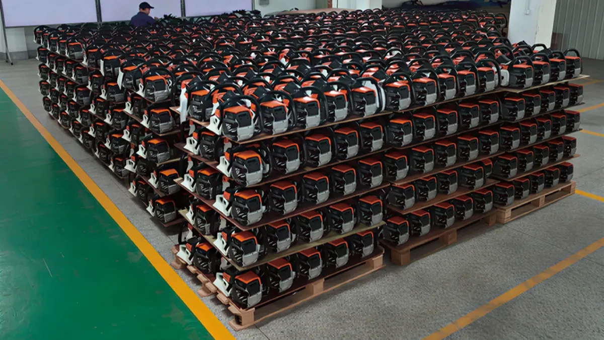
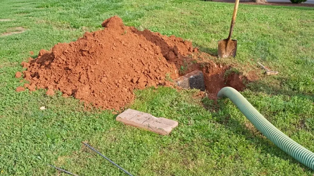
Every stage of chainsaw manufacturing—from metal casting and precision machining to engine assembly, guide bar production, and final testing—plays a critical role in ensuring consistent quality and reliable operation.
This guide explains how modern chainsaws are manufactured step by step, the technologies involved in each production stage, and the quality standards that distinguish a professional chainsaw manufacturer from an average supplier.
What Are the Main Components of a Chainsaw?
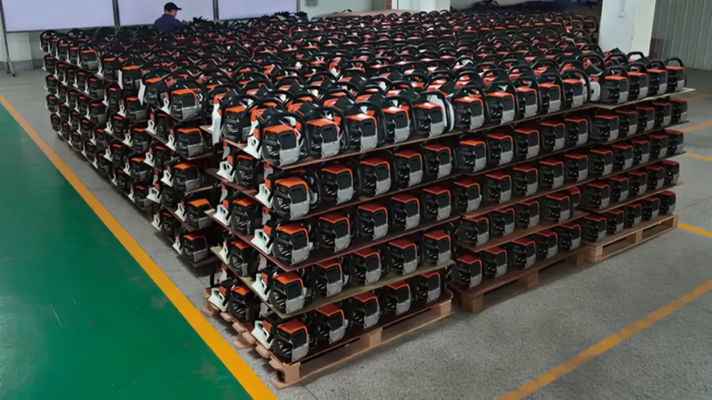
Before exploring the manufacturing process, it’s helpful to understand the major components that make up a chainsaw.
If you’re looking for replacement or OEM components, explore our complete range of chainsaw parts and accessories, including guide bars, ソーチェーン, キャブレター, clutch assemblies, ignition systems, and other essential spare parts.
| 成分 | Function |
|---|---|
| Engine or Motor | Provides cutting power |
| シリンダー & クランクケース | Houses the combustion system |
| クランクシャフト & ピストン | Converts combustion into rotational power |
| キャブレター | Mixes fuel and air efficiently |
| ガイドバー | Supports and guides the saw chain |
| ソーチェーン | Performs the actual cutting |
| Clutch System | Transfers engine power to the chain |
| Chain Brake | Stops the chain quickly for safety |
| 燃料 & Oil Tanks | Store fuel and chain lubrication oil |
| Plastic Housing | Protects internal components while reducing weight |
| Handle & Anti-Vibration System | Improves comfort and operator safety |
ステージ 1: Metal Casting for High-Strength Engine Components
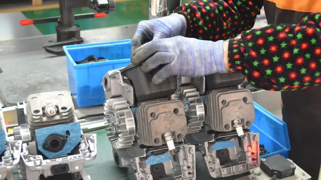
Every chainsaw starts with a strong foundation—the engine. Before any machining or assembly begins, manufacturers create the engine’s structural components through metal casting.
The most important cast parts include the crankcase, cylinder, flywheel, clutch drum, and other load-bearing components. These parts must withstand continuous vibration, high temperatures, and rapid engine speeds while remaining lightweight enough for comfortable operation. ニュートップ further enhances user comfort with an integrated anti-vibration system that minimizes vibration transfer to the handles, allowing safer and more comfortable operation over long working hours. If you’re looking for a dependable chainsaw manufacturer, explore NEWTOP’s full range of professional ガソリンチェーンソー designed for OEM and global distribution.
Different casting processes are selected based on the component’s function:
| Casting Process | Typical Components | Main Advantages |
|---|---|---|
| High-pressure die casting | Aluminum crankcases, engine housings | Excellent dimensional accuracy, high production efficiency |
| Gravity die casting | Cylinder heads, medium-volume components | Better mechanical strength and surface quality |
| Sand casting | Large or low-volume components | Lower tooling cost and greater design flexibility |
| Investment casting | Steel clutch parts, sprockets | High precision and excellent surface finish |
Aluminum alloys are the preferred material for most engine housings because they provide an excellent balance of strength, 耐食性, heat dissipation, and weight reduction. Steel or ductile iron is typically used for heavily loaded transmission and clutch components where higher wear resistance is required.
After casting, every part undergoes trimming, shot blasting, and preliminary dimensional inspection before moving to the machining department. Removing flash, burrs, and surface defects at this stage helps ensure consistent machining accuracy later in production.
ステージ 2: Precision CNC Machining for Critical Parts
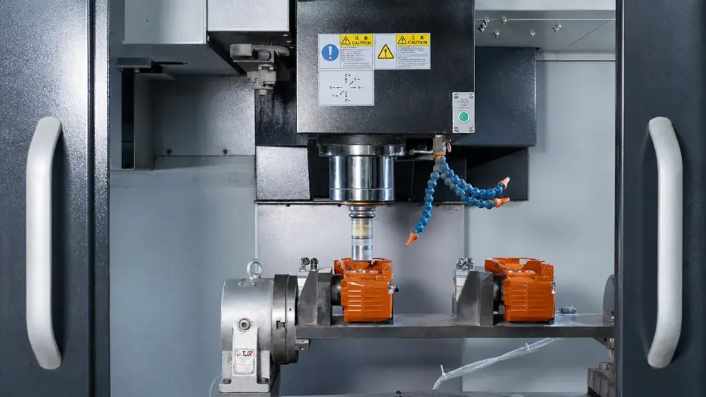
Casting produces the basic shape of each component, but it cannot achieve the tight tolerances required inside a modern chainsaw engine. Precision CNC machining creates the final dimensions that determine engine performance and reliability.
Computer-controlled machining centers perform multiple operations, 含む:
- Cylinder boring
- Crankshaft journal machining
- Bearing seat finishing
- Thread tapping
- Surface milling
- Gear machining
- Drilling oil passages
Many chainsaw manufacturers use multi-axis CNC machining centers to complete several operations in a single setup, improving consistency while reducing production time.
The cylinder bore is one of the most critical machining operations. Its diameter, roundness, and surface finish directly influence piston sealing, 圧縮, 燃費, and engine lifespan. Even minor dimensional errors can increase friction or reduce engine performance.
After machining, coordinate measuring machines (CMM), laser measuring equipment, and precision gauges verify that every critical dimension falls within specification before parts proceed to assembly.
ステージ 3: Plastic Injection Molding for Lightweight Housings
While the engine provides power, many external chainsaw components are manufactured using plastic injection molding to reduce overall weight and improve user comfort.
Typical injection-molded parts include:
- Front and rear handles
- Starter covers
- Air filter covers
- 燃料タンク
- Oil tanks
- Chain brake housings
- Side covers
- Protective guards
Engineering plastics such as PA6, PA66, ABS, polypropylene (PP), and glass fiber reinforced nylon are commonly used because they offer high impact resistance, excellent dimensional stability, and resistance to fuel, 油, and UV exposure.
The injection molding process consists of several stages:
- Plastic pellets are heated until molten.
- The material is injected into precision molds under high pressure.
- Cooling channels solidify the plastic rapidly.
- Parts are automatically ejected from the mold.
- Gates and flash are removed before inspection.
Modern production lines often use robotic systems for automatic part removal and trimming, improving production efficiency while maintaining consistent quality.
Each molded component is inspected for sink marks, warpage, flash, and dimensional accuracy before entering the final assembly line.
ステージ 4: Engine Assembly and Power System Integration
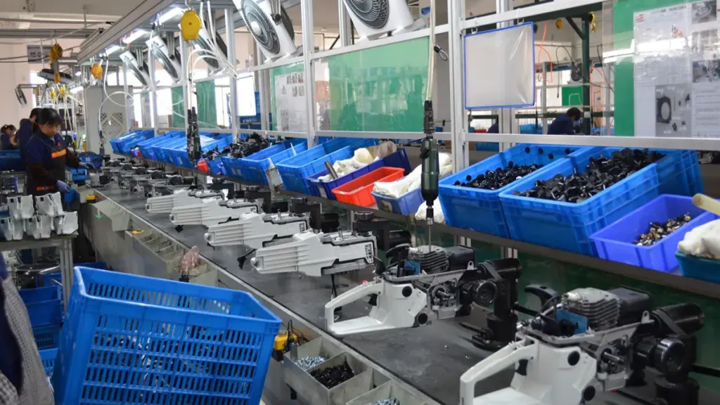
Once all engine components have been manufactured, technicians assemble the complete power unit according to carefully controlled procedures.
A typical assembly sequence includes:
- Installing crankshaft bearings
- Press-fitting the crankshaft
- Installing the piston and piston rings
- Connecting the connecting rod
- Mounting the cylinder
- Installing seals and gaskets
- Assembling the ignition system
- Installing the carburetor
- Mounting the clutch and flywheel
After engine assembly, ignition timing, carburetor settings, and compression are checked before the power unit advances to final product assembly.
Modern production lines also use barcode or QR code tracking to record assembly data, allowing every engine to be traced throughout its manufacturing history.
Maximize Margins With Premium Garden Machinery
ステージ 5: Manufacturing the Guide Bar and Saw Chain
The guide bar and saw chain form the cutting system of a chainsaw and require specialized manufacturing processes separate from engine production.
Guide Bar Manufacturing
Guide bars are typically produced from high-strength alloy steel through:
- Steel blanking
- Heat treatment
- Groove machining
- Nose sprocket installation (for sprocket nose bars)
- 研削
- Surface coating
- Final inspection
Heat treatment increases hardness while maintaining enough toughness to resist bending and cracking during heavy cutting.
Saw Chain Manufacturing
Saw chains are significantly more complex than they appear. A single chain contains hundreds of precisely manufactured components, 含む:
- Cutter teeth
- Drive links
- Tie straps
- リベット
Each cutter tooth is stamped, heat treated, precision ground, and sharpened to produce consistent cutting performance.
Automated riveting machines assemble individual links into complete chains while maintaining accurate chain pitch and articulation. After assembly, chains are lubricated, tension-tested, and inspected for smooth operation.
High-quality chains often feature chrome-plated cutter teeth and hardened rivets to improve wear resistance and extend service life.
ステージ 6: 最終組み立て, Performance Testing, and Quality Inspection
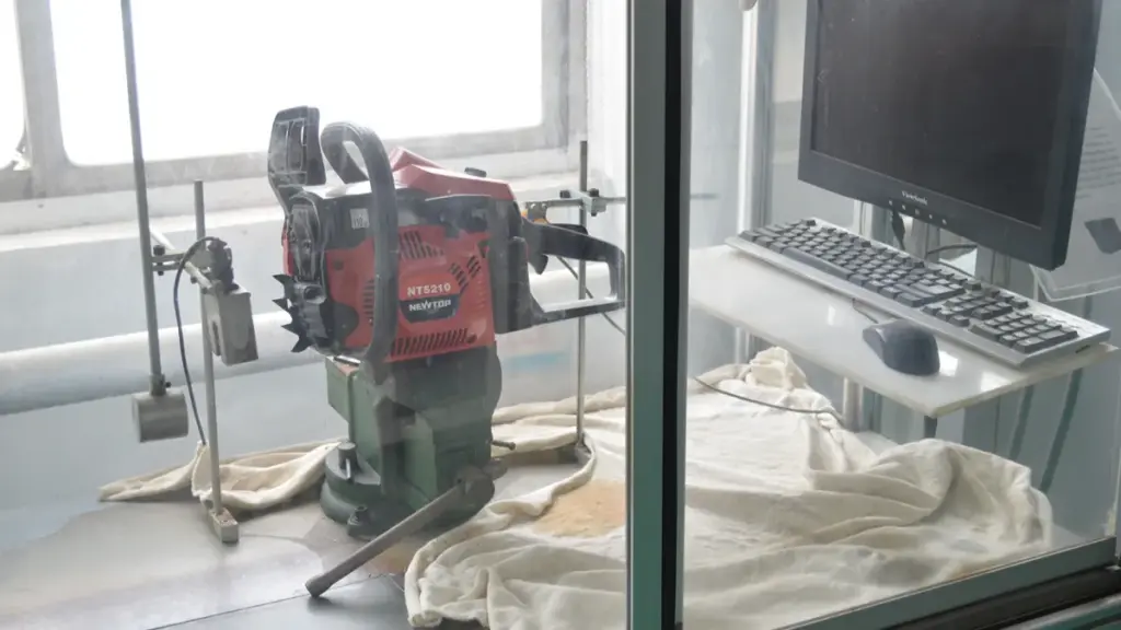
The final stage brings together every component into a finished chainsaw ready for shipment.
During final assembly, workers install the completed engine, ガイドバー, saw chain, plastic housings, fuel system, ignition components, handles, safety devices, and control mechanisms.
Each chainsaw then undergoes multiple quality inspections before packaging.
Typical production tests include:
| Inspection Item | 目的 |
|---|---|
| Torque verification | Ensure fasteners meet assembly specifications |
| Compression test | Verify engine sealing performance |
| Ignition test | Confirm reliable spark generation |
| Fuel system leak test | Prevent fuel leakage |
| Chain brake test | Verify operator safety |
| Idle speed test | Ensure stable engine operation |
| Maximum RPM test | Confirm engine performance |
| Noise and vibration test | Evaluate operating comfort |
| 目視検査 | Check cosmetic quality and assembly accuracy |
ニュートップにて, every chainsaw model undergoes rigorous endurance testing of up to 200 時間 under demanding operating conditions. Built with high-quality components and strict manufacturing standards, NEWTOP chainsaws are engineered to deliver more than 500 時間 of working life under professional use, providing reliable performance for forestry, 造園, および商用アプリケーション.
Only after passing all inspection procedures are chainsaws cleaned, packaged with accessories and manuals, and prepared for shipment.
What Certifications and Standards Should a Chainsaw Factory Meet?
Certifications demonstrate that a reliable chainsaw manufacturer follows internationally recognized quality, 安全性, and environmental requirements.
Depending on the target market, a reliable chainsaw factory should comply with standards such as:
| 認証 | 目的 |
|---|---|
| ISO 9001 | 品質マネジメントシステム |
| CE | Compliance with European safety requirements |
| GS | German product safety certification |
| EPA | U.S. 排出ガスコンプライアンス |
| 炭水化物 | California emissions standards |
| RoHS | 有害物質の制限 |
| 到着 | Chemical safety compliance |
ニュートップにて, quality and compliance are integrated into every stage of manufacturing. Our factory operates under an ISO 9001-certified quality management system, and our products comply with international standards and certifications, 含む CE, GS, EPA, RoHS, and REACH, depending on the product model and destination market. This allows us to support OEM customers across Europe, 北米, and many other global markets with confidence.
How Quality Control Ensures Reliable Chainsaw Performance

Consistent chainsaw performance relies on strict 品質管理, from precise component tolerances to rigorous safety validation and independent lab testing before shipment.
| QC Phase | Key Focus Area | Primary Objective |
|---|---|---|
| Specifications | Dimensional & Material Limits | Establish production baselines. |
| Incoming QC | Bore Size & Groove Width | Block defective parts early. |
| In-Process | Mistake-proofing & PFMEA | Prevent assembly errors. |
| Final Testing | 切断速度 & 安全性 | Validate functional performance. |
Establishing Technical Specifications and Supplier Standards
Quality control begins long before parts hit the assembly line. Manufacturers rely on detailed technical documents to set exact boundaries for what constitutes an acceptable component. This foundation dictates how the supply chain operates and prevents vague standards from degrading the final product.
- Defining dimensions: Engineering teams set precise dimensional tolerances for cylinders, ガイドバー, and chains to ensure alignment and prevent vibration.
- Material selection: Production managers establish strict requirements for wear-resistant steel alloys and impact-resistant plastics to survive harsh forestry environments.
- Supplier audits: Procurement teams audit partner factories for dedicated power tool production lines, advanced CNC machining, and specialized heat treatment capabilities.
Incoming Quality Control (IQ) for Critical Components
Catching defects at the source is significantly cheaper and safer than pulling apart a finished chainsaw. Incoming Quality Control (IQ) filters out substandard raw materials and purchased parts before they compromise the powerhead or cutting system.
- Cutting attachment checks: Inspectors test guide bar groove width, rail parallelism, and chain pitch tolerances against technical drawings.
- Engine component verification: Technicians verify cylinder bore size, roundness, and piston dimensions using coordinate measuring machines.
- Hardware validation: Staff check fasteners, trigger lock-outs, and chain brake springs to guarantee safety devices will function under load.
In-Process Controls and Manufacturing Stability
High-volume production lines introduce variables that can drift over a shift. In-process controls keep manufacturing stable, isolating individual workstations to detect assembly errors the moment they happen.
- Process mapping: Engineers map manufacturing steps with PFMEA to prioritize controls on high-risk operations like clutch installation and carburetor tuning.
- Assembly aids: Operators utilize mistake-proofing jigs and go/no-go fixtures to prevent incorrect component alignment.
- Mid-line checks: QC staff conduct intermediate functional tests on engine start behavior and preliminary guide bar tracking.
Final Performance Testing and Safety Validation
Once mechanical assembly concludes, testing shifts from static dimensions to dynamic performance. Every unit or sampled batch must prove it can cut efficiently and shut down safely under simulated field conditions.
- Cutting capability: Technicians perform test cuts on standardized wood samples to verify cutting speed, smoothness, and chip evacuation.
- Safety systems: Inspectors validate chain brake reaction times, throttle lock-outs, and kill switch reliability.
- Visual and physical fit: QA teams check final assembly for the correct chain tension range, secure guard alignment, and overall cosmetic integrity.
Independent Verification and Documentation Standards
International buyers trust independent validation over internal factory reports. Third-party testing and rigorous documentation keep global supply chains honest and protect the brand’s reputation upon import.
- Third-party audits: Brands engage independent inspection firms for AQL pre-shipment sampling and compliance lab testing.
- Physical baselines: Production teams use approved golden samples as the ultimate reference for fit, 仕上げる, and performance.
- Strict record-keeping: Factories maintain detailed bilingual specification packs and order confirmations to eliminate ambiguity and prevent scope drift.
Why Choose NEWTOP as Your OEM Chainsaw Manufacturer?
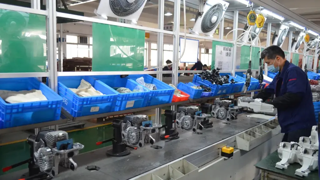
Partnering with NEWTOP gives distributors a direct pipeline to fully certified, scalable power equipment built for immediate global market entry.
Selecting the right manufacturing partner involves more than comparing prices. A capable factory should combine engineering expertise, 安定した生産能力, strict quality management, 応答性の高いカスタマーサポート.
で ニュートップ, we integrate the entire manufacturing process—from component production to final assembly—to ensure consistent product quality across every order.
Our manufacturing advantages include:
- より多い 20 years of manufacturing experience in outdoor power equipment
- Modern production facilities with advanced CNC machining and automated assembly
- Strict quality control throughout every production stage
- Comprehensive testing before shipment
- Support for OEM and ODM customization
- Flexible production capacity for distributors and brand owners
- Global export experience across multiple international markets
Whether you are launching a new chainsaw brand or expanding an existing product line, NEWTOP can provide dependable manufacturing support, stable quality, and long-term partnership for your business growth.
よくある質問
Can a Chinese factory handle OEM chainsaw orders?
Chinese factories easily handle end-to-end OEM chainsaw production. You can expect complete support from design adaptation and power parameter tuning to custom branding and export packaging. Facilities run dedicated lines for gasoline, corded electric, and battery-powered lithium-ion models.
How long does mass chainsaw production typically take?
Mass production cycles depend on the project scope. Standard repeat batches finish in 5 に 15 days once parts arrive at the assembly line. New OEM runs requiring prototype validation and custom molds take 3 に 6 weeks. Once on the main conveyor, physical assembly and testing for a single unit take just 10 に 30 分.
How do manufacturers test chainsaws before shipping?
Quality control teams run chainsaws through dedicated testing workshops before packaging. They test engine seals under pressure, calibrate idle and high-speed RPM thresholds, and perform physical wood-cutting trials. Inspectors also test critical safety components, including the chain brake reaction time, throttle lock-out, and the engine kill switch.
What materials are used to ensure chainsaw durability?
Professional chainsaw production relies on high-carbon and alloy steels for guide bars and saw chains. Premium cutting teeth often feature double chrome plating or brazed carbide inserts to reduce wear. For the powerhead, manufacturers cast engine blocks from lightweight aluminum or magnesium alloys and mold outer housings from impact-resistant engineering plastics.
What certifications should I look for in a chainsaw manufacturer?
Look for factories operating under ISO 9001 quality management and ISO 14001 environmental standards. For the product itself, target markets dictate the exact requirements. European imports demand CE marking covering Machinery and EMC directives, along with noise and vibration compliance. Verified test reports from recognized labs like TÜV Rheinland provide the strongest proof of reliability.
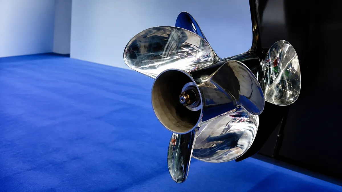
Choosing the right outboard propeller is not simply about finding a model that fits the engine shaft. A propeller directly affects acceleration, トップスピード, 燃費, engine load, そして全体的なボート体験.
For boat builders, 販売代理店, and marine equipment buyers, selecting the wrong propeller can lead to poor performance, 過度の振動, higher fuel costs, and even long-term engine issues.
A reliable propeller selection process should consider several factors, including engine specifications, boat characteristics, 動作条件, blade design, material choice, and supplier capability.
This guide explains the key points buyers should check before purchasing an outboard propeller and how to make a more accurate selection for different applications.
What Key Information Should You Prepare Before Choosing a Propeller?
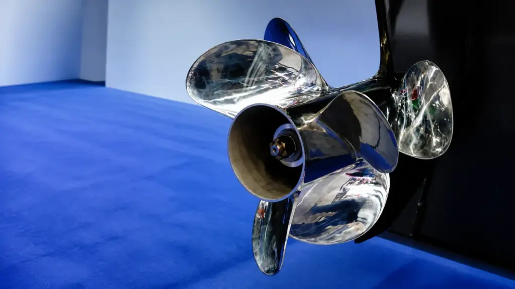
Before comparing propeller models, collect accurate information about the engine, boat, and daily use. This reduces fitting errors and gives the supplier enough data to recommend a suitable starting configuration.
Prepare the following details:
| Data Category | Metrics to Record |
|---|---|
| Current Propeller | 直径, ピッチ, 回転, blade count, 材料, hub splines |
| Engine Details | Rated HP, gearcase size, target WOT RPM, actual WOT RPM |
| Boat Profile | 長さ (LOA), hull shape, operating weight, speed goals |
| Usage Environment | Primary activity, cruise speed, water conditions (fresh/salt/shallow) |
| Benchmarks | GPS speed at WOT, time to plane, ventilation in turns |
Current Propeller Specifications
Your existing propeller serves as the baseline for any future adjustments. You need exact numbers off the current hub or blades to know which direction to adjust your pitch or diameter.
- 直径とピッチ: Record these numbers (usually stamped on the barrel, のように 14 × 19) to establish your starting point.
- Rotation direction: Identify if the prop uses right-hand or left-hand rotation. This matters heavily for twin-engine setups.
- Blades and material: Note if you run a 3-blade or 4-blade design, and whether it is cast aluminum or stainless steel.
- Hub and shaft details: Count the splines on the prop shaft and measure the shaft diameter to ensure your replacement physically fits the gearcase.
Engine Details and WOT RPM Limits
Engine specifications define your operating envelope. Your motor has a specific RPM band where it makes peak power safely, and your prop must keep the engine inside that band.
- HP and gearcase size: Verify your rated horsepower and gearcase dimensions. These dictate which propeller families fit the outboard.
- Target WOT RPM: Find the manufacturer’s recommended Wide Open Throttle (ウォット) 回転数範囲. Modern outboards usually target 5,000 に 6,000 回転数.
- Actual WOT RPM: Measure your current wide-open RPM under a normal load. This tells you if the engine is over-revving or lugging.
- Trim systems: Note if the boat has power trim or trim tabs. These systems dictate how you tune the hull attitude to reach optimal RPM.
Boat Characteristics and Load Profile
Hull design and operating weight directly influence thrust requirements. A heavy pontoon pushes water differently than a light bass boat, demanding a totally different blade geometry.
- Hull dimensions: Document the length overall (LOA), hull material, and bottom shape (like deep-V or flat-bottom). These dictate drag and required lift.
- Operating weight: Calculate your realistic load. Include fuel, 乗客, ギヤ, and livewells.
- Load frequency: Identify if you frequently run heavily loaded. Heavy loads often require stepping down in pitch or moving to a 4-blade prop to maintain thrust.
- Speed targets: Define your present top speed against your desired top speed. This guides the tradeoff between pitch and acceleration.
Usage Profile and Operating Environment
How and where you drive determines the optimal propeller style. You must align the design with your primary on-water activities to get the best efficiency.
- Primary use: Specify if you focus on high-speed cruising, heavy towing for watersports, or commercial work.
- Running speeds: Identify your typical throttle positions. This determines if you optimize for mid-range fuel economy or absolute top-end speed.
- 水の状態: Consider your environment. Abrasive, 砂っぽい, or shallow waters often demand the durability of stainless steel over standard aluminum.
Real-World Performance Benchmarks
Never buy a new propeller without testing the old one first. You need hard performance data to compare against your post-installation results.
- Baseline test runs: Take the boat out and record maximum RPM and GPS speed at wide-open throttle, trimming up just before the prop cavitates.
- Acceleration metrics: Evaluate your hole shot, the time it takes to get on plane, and the boat’s ability to hold a plane at lower speeds.
- Handling checks: Monitor the steering for signs of propeller ventilation, excessive slip during hard turns, or cavitation in rough chop.
How Do Diameter and Pitch Affect Propeller Performance?
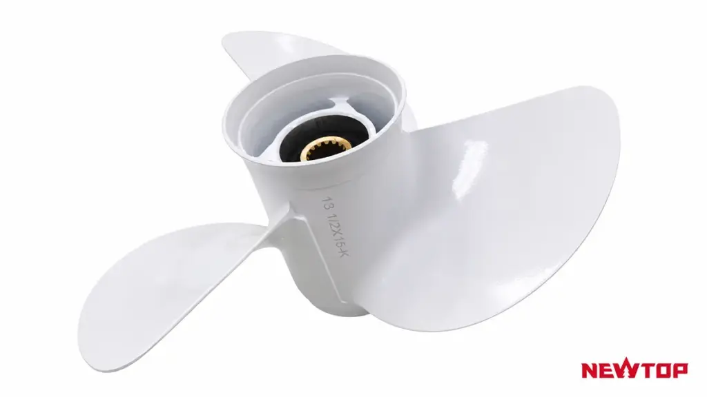
Diameter and pitch are two of the most important measurements in propeller selection. They determine how efficiently an outboard propeller converts engine power into thrust and directly influence acceleration, トップスピード, 燃費, and engine RPM.
Before choosing a replacement propeller, buyers should understand what these two specifications mean and how they work together. A propeller marked as 14 × 19, 例えば, indicates a 14-inch diameter and a 19-inch pitch. The first number represents diameter, while the second number represents pitch.
For a more detailed explanation of propeller markings and how these measurements affect performance, buyers can refer to our guide on what pitch and diameter mean on an outboard propeller.
直径 refers to the distance across the full circle made by the rotating blades. A larger diameter generally produces more thrust because it moves more water with each rotation.
Large-diameter propellers are commonly used for:
- Heavy boats
- Commercial applications
- Boats that require strong pulling power
- Low-speed operation
A smaller diameter propeller usually allows higher RPM and may support better top-speed performance on lightweight boats.
ピッチ refers to the theoretical distance a propeller moves forward in one complete rotation without considering slip. 例えば, a 19-inch pitch propeller is designed to move approximately 19 inches per rotation under ideal conditions.
The relationship between pitch and performance is:
| Pitch Choice | Performance Effect |
|---|---|
| Lower pitch | より速い加速, stronger thrust, easier engine operation |
| Higher pitch | Higher potential speed, lower RPM, suitable for light loads |
しかし, increasing pitch does not always increase speed. ピッチが高すぎる場合, the engine may struggle to reach its recommended RPM range, causing poor acceleration and increased stress.
A proper selection balances pitch, 直径, engine power, and boat load. Many buyers use factory recommendations as a starting point and then adjust based on real operating conditions.
Source Durable Garden Machinery at Competitive Prices
How Does the Number of Blades Influence Speed, 推力, and Fuel Efficiency?
Blade count dictates the balance between top speed and load capacity. Fewer blades reduce drag for maximum speed, while more blades provide necessary grip for heavy loads.
The Relationship Between Blade Area and Drag
Every propeller blade moving through water creates surface friction and pressure drag. Fewer blades result in a smaller total wetted area, directly translating to lower hydrodynamic drag and higher potential open-water efficiency.
Adding blades increases the Blade Area Ratio (BAR). A higher BAR gives the propeller significantly more grip on the water, reducing slip and ventilation. The trade-off is higher hydrodynamic interference between the blades, demanding more power to turn at the exact same RPM.
How Blade Count Affects Top Speed
Two-blade propellers theoretically offer the highest top speeds on lightly loaded hulls because they encounter minimal drag. For most recreational planing hulls, three-blade designs hit the sweet spot. A well-matched three-blade propeller consistently runs 5% に 10% faster at wide-open throttle compared to a four-blade setup.
Upgrading to a four-blade propeller usually cuts peak speed by about 2 に 3 時速マイル. Yet, these high-blade configurations maintain effective speed much better in rough water or high-trim conditions by actively resisting blowout.
Thrust Capabilities and Load Management
Total thrust depends heavily on the total blade area. A propeller with fewer blades forces each blade to carry a higher unit thrust. Push a low-blade-count prop too hard under a heavy load, and you risk severe cavitation or structural stress at the blade root.
Four-blade and high-BAR three-blade propellers excel at managing demanding workloads. You need these configurations for:
- Heavy Boats: Lifting heavy hulls onto plane quickly.
- Towing Applications: Delivering strong mid-range acceleration.
- Limited Clearances: Maximizing thrust when gearcase size limits the maximum diameter.
Fuel Efficiency and Optimal Engine Loading
For standard recreational setups, a correctly sized three-blade propeller delivers the best steady-cruise fuel economy. The minimal drag allows the outboard to run efficiently near its peak torque band.
Adding a fourth blade increases the physical load on the engine. You almost always need to drop the pitch to keep the wide-open throttle RPM within the manufacturer’s optimal range. On heavily loaded boats, a four-blade propeller can actually improve real-world fuel efficiency. By drastically reducing slip, it holds the boat on plane at lower RPMs, burning less fuel than a three-blade prop struggling to grip the water.
Should You Choose an Aluminum or Stainless Steel Propeller?
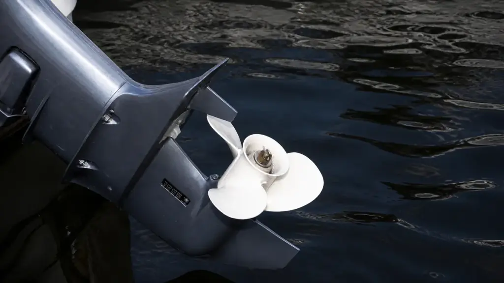
Aluminum offers budget-friendly protection for shallow waters and lower horsepower, while stainless steel delivers speed, グリップ, and durability for high-performance outboards and saltwater environments.
For buyers who want to understand the detailed differences between these two materials, including strength, 耐久性, メンテナンス, and application scenarios, our guide on aluminum vs stainless steel outboard motor propellers provides a complete comparison.
Matching Material to Outboard Horsepower
Outboard horsepower directly dictates the ideal propeller material. For motors under 30 馬力, manufacturers almost exclusively equip factory aluminum propellers. Stainless steel options in this range remain scarce and offer little practical performance benefit.
Mid-range engines between 30 そして 70 hp pair perfectly with aluminum for general recreational boating. The power output at this level rarely causes severe blade flex, keeping performance stable for everyday use. Once you step up to outboards producing 75 hp and above, the operating dynamics change. These engines generate high torque and push heavier loads, making stainless steel the standard choice to handle the increased thrust without losing blade shape.
Durability and Lower Unit Risk
How a propeller reacts to underwater impacts determines the safety of your lower unit gears. You must evaluate your primary operating environment before making a choice.
- Sacrificial protection: Aluminum acts as a sacrificial component, bending or cracking upon impact to absorb shock and protect lower unit gears.
- Impact transfer: Stainless steel withstands normal wear and minor impacts, but transfers heavy strike forces directly to the prop shaft.
- Shallow hazards: Boaters navigating shallow, stump-filled, or rocky rivers should select aluminum to minimize expensive gearcase repairs.
- Saltwater endurance: Marine environments heavily favor stainless steel due to its superior long-term corrosion resistance.
Hydrodynamic Performance and Handling
Material stiffness heavily influences thrust efficiency. Manufacturers cast aluminum blades thicker to achieve necessary strength, but they still flex under heavy loads. This flexing slightly reduces top-end speed and high-RPM stability. Stiff, thin stainless steel blades maintain their precise pitch and shape under pressure, improving thrust efficiency and maximizing water displacement.
Upgrading to a stainless steel model often yields a 2 に 3 mph speed gain alongside stronger acceleration for heavy loads. Stainless steel also holds cupping better than aluminum. This structural advantage ensures reliable grip during tight turns and drastically reduces ventilation issues on the water.
Cost Comparison and Lifespan Value
An aluminum propeller costs roughly one-third the price of a comparable stainless steel model. Budget-conscious buyers and boaters who frequently replace damaged props benefit the most from this low upfront cost. The inexpensive replacement strategy makes sense when striking rocks or stumps is a routine risk.
Stainless steel requires a much higher initial investment. It provides exceptional lifespan in deep, obstruction-free waters where impact damage is rare. The long-term value quickly shifts to stainless steel for performance rigs, as the durable material eliminates the need for frequent replacements and maintains optimal fuel efficiency over thousands of hours of use.
How Do Engine Horsepower and Gear Ratio Affect Propeller Selection?
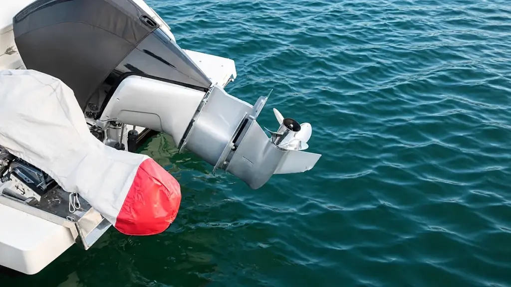
Horsepower dictates the maximum propeller size an engine can efficiently turn, while gear ratio determines shaft speed. 一緒に, they establish the exact pitch required to hit target WOT RPM.
The Role of Engine Horsepower in Propeller Sizing
Engine horsepower sets the baseline power budget for moving a boat efficiently. A higher horsepower rating allows an outboard to turn a larger diameter or a higher-pitch propeller without struggling. Buyers must match the propeller to the engine’s usable horsepower at the intended operating RPM, rather than looking strictly at peak horsepower marketing numbers.
If you choose an oversized or over-pitched propeller, the engine will lug and fail to reach its intended power band. Undersize the propeller, and the engine will over-rev, leaving valuable performance unused and risking mechanical damage.
How Gear Ratio Determines Propeller Shaft Speed
Gear ratio acts as a primary input that fundamentally changes the final propeller load. It is not just a secondary detail. You calculate propeller shaft RPM directly by dividing the engine RPM by the gear ratio.
A higher numerical gear ratio reduces the prop shaft speed and multiplies torque. To restore the desired boat speed, this setup requires a higher-pitch propeller. 逆に, a lower numerical gear ratio spins the propeller faster at a given engine RPM, requiring reduced pitch to prevent the engine from over-revving.
Balancing Pitch and Final RPM for Optimal Performance
Adjusting the gear ratio triggers a chain reaction in pitch selection. Increasing a gear ratio numerically usually requires stepping up the propeller pitch by two to four sizes. Since a single pitch size change typically alters engine speed by 250 に 350 回転数, pitch adjustments serve as the ideal mechanism for fine-tuning wide-open-throttle (ウォット) 回転数.
Operating conditions also alter this power dynamic. Heavy boat loads and high elevations demand less pitch to keep the engine from dropping below its optimal power band. For high-RPM outboard designs, manufacturers frequently use reduction ratios of 2.3:1 or higher to properly manage the aggressive propeller shaft speed and hydrodynamic load.
Practical Selection Steps for Outboard Buyers
Start the selection process by identifying the engine’s rated horsepower, gear ratio, and recommended WOT RPM range. From there, execute a systematic testing sequence to dial in the correct specifications:
- Baseline Selection: Select a propeller size that lets the engine reach target RPM under expected load, elevation, and water conditions.
- Pitch Adjustment: Reduce pitch if the engine fails to reach target RPM, or increase pitch if the engine over-revs during initial testing.
- Sea Trial Verification: Conduct a final loaded test run to account for specific real-world variables like hull drag, running weight, and ventilation behavior.
How Does Boat Type Influence the Right Propeller Choice?
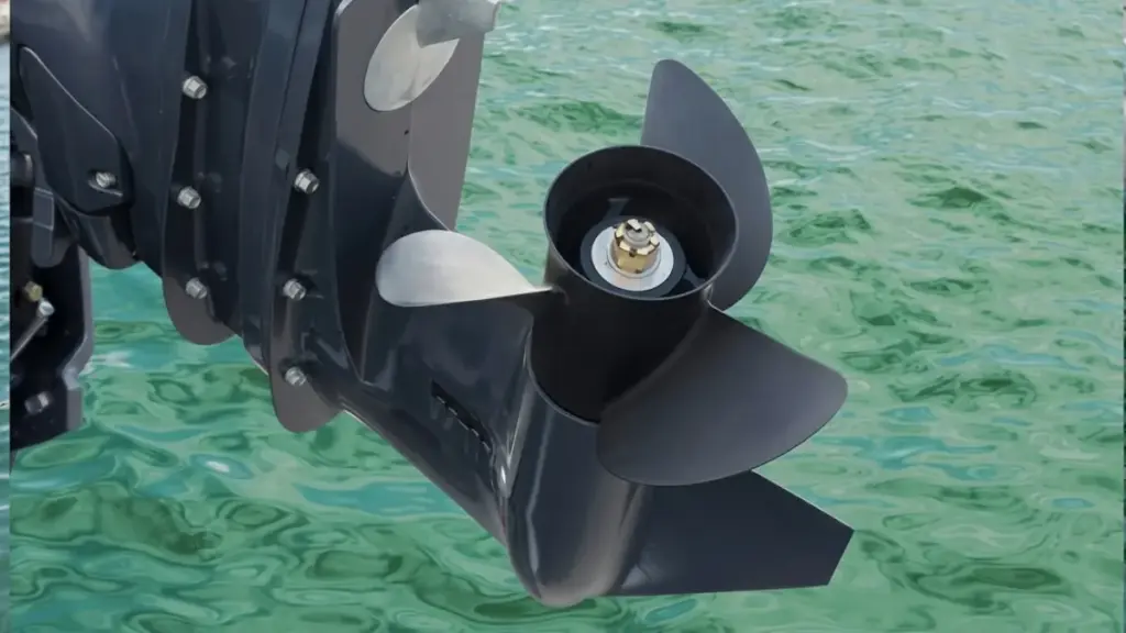
Hull design and typical boat load dictate required thrust and RPM. Matching pitch and diameter to your specific vessel type prevents engine lugging and maximizes hydrodynamic efficiency.
High-Speed Planing and Performance Boats
ライト, performance-focused hulls like bass boats or sport rigs require setups that minimize drag once on plane. Your primary goal is converting engine torque directly into top-end speed while keeping the outboard near its maximum RPM limit.
To achieve this, operators utilize higher pitch and moderate-to-smaller diameter profiles. High-speed setups rely heavily on 3-blade stainless steel propellers, which deliver the durability and thin-blade efficiency needed to push past 50 mph without flexing.
Watersports and Tow-Sport Configurations
Pulling wakeboarders, skiers, or heavy tubes demands a massive initial surge of thrust. Absolute top speed takes a backseat to a strong hole shot and smooth mid-range pulling power.
Tow boats require lower pitch and larger diameter profiles to move heavily ballasted setups without dropping below the engine’s power band. Owners frequently utilize 4-blade propellers to improve low-speed handling, reduce slip, and keep the boat securely on plane.
ポンツーン, Tritoons, and Heavy Cruisers
These vessels push a massive amount of water. High frontal drag and heavy, variable passenger loads mean your propeller must maximize water displacement rather than chase speed.
Pontoons and heavy cruisers benefit from larger diameter and moderate-to-low pitch to generate adequate low-speed thrust. This exact configuration prevents engine lugging and ensures the motor reaches its specified WOT RPM despite the heavy structural drag.
General Fishing and All-Purpose Vessels
Aluminum fishing boats and versatile center consoles operate across diverse conditions. The ideal setup balances rapid acceleration, mid-range cruise efficiency, and precise low-speed maneuverability around docks or structure.
Most operators pair moderate pitch with 3-blade designs to achieve versatile performance during long runs. When conditions dictate, shifting to 4-blade setups provides better grip offshore or improves shallow-water stern lift on flats boats.
Sailboats and Displacement Hulls
Displacement hulls cannot exceed their theoretical hull speed regardless of applied power. Propeller selection must focus entirely on low-speed thrust and reliable maneuvering in tight quarters.
Operators use large-diameter, low-pitch profiles to push displacement hulls efficiently at modest engine speeds. This approach protects auxiliary outboards from overloading when fighting strong currents or heavy headwinds.
What Operating Conditions Should Buyers Consider?
Propeller selection requires analyzing actual boat weight, typical water conditions, engine RPM limits, and horsepower output to prevent drivetrain damage and maximize fuel efficiency.
Boat Load and Usage Patterns
Evaluating typical operating loads is the first step in propeller selection. A boat behaves entirely differently when running solo compared to a hull weighed down by passengers, heavy gear, full fuel tanks, or towing duties.
Always prop the boat so the engine reaches the upper end of its wide-open-throttle (ウォット) rpm range when lightly loaded. This rpm buffer prevents the engine from lugging once you introduce heavy weight.
- Variable Usage: Boats shifting between light solo fishing trips and fully loaded family cruising require either a compromise propeller or a dedicated two-prop setup.
- Heavy-Duty Operations: Towing, レスキュー, and workboats demand high, continuous thrust. These roles favor larger diameter, lower-pitch propellers designed to run efficiently at lower rpm.
Engine RPM Matching and Performance Goals
The propeller acts as the final gear ratio between the engine and the water. It must keep the outboard operating inside the manufacturer-specified WOT rpm range. Operating outside this band degrades fuel efficiency and accelerates mechanical wear.
Pitch adjustments directly dictate engine speed. Increasing pitch by one inch typically decreases WOT rpm by approximately 200 回転数, while decreasing pitch raises it by the same amount.
- Planing Hulls: These setups require rapid hole shot and target a controlled slip factor of 8-15% at WOT for peak efficiency.
- Displacement Hulls: Slow-speed vessels ignore top-end speed to focus entirely on generating maximum low-end torque.
- Real-World Validation: Empirical WOT testing with proper trim adjustments is the only reliable way to validate rpm matching and fuel burn under actual operating conditions.
Water Environment and Surface Conditions
The physical water environment dictates blade geometry. Rough water causes the hull to pitch, increasing the risk of the propeller breaking the surface. Propellers with increased blade area or aggressive cupping hold water better and reduce ventilation in heavy chop.
Calm water applications allow operators to take the exact opposite approach, prioritizing higher pitch and lower drag designs to push top-end speed.
- Hazardous Environments: Shallow or debris-filled waters guarantee eventual bottom strikes. These areas require durable materials and responsive motor trim capabilities to protect the drivetrain.
- Water Flow Quality: Propellers require clean, undisturbed water to generate optimal thrust. Poor mounting heights or excessive hull turbulence will cause aeration and immediate power loss.
Outboard Horsepower and Structural Demands
Engine output strictly determines the required material strength. High-horsepower outboards, typically rated at 140 hp and above, exert extreme torque that overwhelms weaker metals and causes aluminum blades to flex.
Rigid stainless steel propellers are the primary choice for high-output engines. Stainless maintains its exact designed geometry under heavy loads and high speeds, providing predictable thrust and maximum traction.
- Lower-Horsepower Applications: General-purpose and lower-hp engines perform exceptionally well with aluminum propellers. They offer a cost-effective, impact-forgiving alternative that acts as a sacrificial part during bottom strikes.
- Exhaust Compatibility: You must verify the propeller design integrates correctly with the lower unit’s specific exhaust routing, particularly for through-hub exhaust systems.
What Common Propeller Selection Mistakes Should Buyers Avoid?
Avoiding common propeller selection mistakes—like guessing pitch, ignoring typical loads, or neglecting lower unit fitment—saves fuel, protects the engine, and prevents costly on-water failures.
Misjudging RPM, ピッチ, and Load Requirements
Buyers often sabotage outboard performance by selecting a propeller without validating how it impacts the engine’s actual operating range.
- Ignoring the WOT RPM range: Failing to match the propeller to the engine’s recommended Wide Open Throttle (ウォット) limits causes the engine to lug under heavy load or over-rev at top speed.
- Prioritizing theoretical top speed: Selecting pitch just to hit a high top-speed number ignores the inverse effect pitch has on RPM and low-end acceleration.
- Testing on an empty boat: Finalizing a prop choice with a light hull gives false data. The boat will struggle to plane once fully loaded with passengers, ギヤ, そして燃料.
Treat the manufacturer’s specified WOT RPM as a hard constraint. You must hit this target under normal, real-world operating loads to ensure efficient running and long engine life.
Overlooking Blade Count and Material Trade-Offs
Many buyers mistakenly believe that simply adding blades or buying the cheapest material will fix performance issues. Every design change shifts the performance curve.
- Assuming more blades equal better performance: Buyers often switch from three to four blades hoping for an outright upgrade, not realizing the extra drag typically drops WOT RPM by 50 に 150 回転数.
- Shopping by material price: Choosing aluminum over stainless steel strictly to save money ignores your actual environment. Soft aluminum deforms under high load, while stainless steel maintains its shape and efficiency at high speeds.
- Ignoring the primary use case: Buying a propeller designed for fast, solo runs fails if you spend 80% of your time towing wakeboarders or carrying a heavy crew.
Match the blade geometry and material to your actual daily environment. A high-performance stainless steel prop shines in open water but transfers severe shock to the gearcase if you strike a submerged stump in shallow rivers.
Using Flawed Testing and Adjustment Methods
Troubleshooting a sluggish boat requires a systematic approach. Guessing at propeller specs without proper baseline data leads to wasted money and unresolved engine strain.
- Changing multiple variables at once: Swapping pitch, blade count, and material in a single step makes it impossible to isolate which change improved or hurt performance.
- Ignoring GPS boat speed: Focusing strictly on tachometer readings without verifying actual speed hides secondary issues like extreme prop slip.
- Blaming the prop prematurely: Buyers often fault the propeller for sluggish planing when the real culprit is excessive hull drag, the wrong engine mounting height, or poor trim angle.
Establish a clear baseline with your current setup first. Make single, incremental adjustments—usually starting with pitch—and test the results on the water before changing another variable.
Neglecting Fitment, メンテナンス, and Spares
Even the perfectly pitched propeller fails if it does not physically integrate with the outboard gearcase or lacks basic maintenance.
- Guessing hub compatibility: Buying a prop without checking spline counts, hub system types, or matching thrust washers leads to stripped splines and lower unit damage.
- Ignoring physical damage: A slightly bent blade or fishing line wrapped around the prop shaft mimics the symptoms of incorrect pitch.
- Running without a spare: Operating without a backup prop leaves you stranded after a severe strike and eliminates your ability to swap to a lower-pitch prop for unexpectedly heavy loads.
Verify fitment against the engine transom tag before purchasing. Inspect the prop hub assembly periodically to catch early signs of slippage or corrosion.
最終的な考え
Buyers should evaluate engine specifications, ボートタイプ, 動作条件, blade design, material choice, and supplier reliability when bulk buying outboard motor propellers.
The right propeller improves acceleration, 燃費, 取り扱い, そしてエンジン性能も, while the wrong choice can reduce efficiency and increase operating costs.
販売代理店様向け, boat manufacturers, and marine equipment companies, working with an experienced outboard propeller supplier provides better product consistency and long-term support.
With advanced manufacturing capability, precision-balanced aluminum and stainless steel propellers, and OEM/ODM production experience, NEWTOP helps global partners develop reliable propeller solutions for different marine applications.
よくある質問
What should I check before buying an outboard propeller?
Verify your boat’s primary use, typical load profile, and desired performance goals. You must confirm engine specifications, including the brand, horsepower, shaft type, and the manufacturer’s recommended wide-open-throttle (ウォット) 回転数範囲. Collect baseline data from your current prop, such as diameter, ピッチ, 材料, and observed WOT RPM, to guide your replacement choices.
How do I choose the right propeller pitch?
Selecting pitch relies on matching the propeller to your engine’s recommended WOT RPM range. Test your current setup at full throttle with a normal load. If the RPM falls below the recommended band, decrease the pitch. If the RPM exceeds the limit, increase the pitch. Changing the pitch by one inch generally alters the engine speed by 150 に 200 回転数.
Is stainless steel better than aluminum for all users?
いいえ. Stainless steel provides superior rigidity, higher top speeds, and excellent saltwater corrosion resistance, making it ideal for high-horsepower engines. Aluminum is highly cost-effective and serves as a sacrificial metal. In shallow or hazard-prone waters, an aluminum propeller will bend or break upon impact, which helps protect the expensive gearcase from severe damage.
What is the best propeller for heavy boats?
Heavy vessels require maximum static thrust and control rather than high top speed. The best approach is selecting a larger diameter propeller with a lower pitch to ensure the engine reaches its target RPM under heavy load. A four-blade design is frequently recommended to improve grip, accelerate planing, and provide smoother handling in rough conditions.
How do I confirm hub compatibility?
Read your engine’s transom tag to find the exact make, モデル, 年, and gearcase code. Match this data against the new propeller’s specifications, ensuring the spline count and shaft diameter align perfectly. You also need to identify whether your outboard uses a fixed splined bore or a modular insert kit, and verify the proper thrust washer sequence.
What documents should a propeller supplier provide?
A standard procurement package should include a Certificate of Conformance (CoC), material certificates, and final inspection or balance reports. For commercial or classed vessels, suppliers must also provide traceability records and relevant approval documents to prove the delivered hardware meets the required engineering standards.
How important is sample testing before a bulk order?
On-water sample testing is critical because catalog specifications cannot predict how a hull and engine combination will react to complex loads. Testing a small batch validates WOT RPM, 取り扱い, そして燃費. Skipping this step risks large-scale inventory issues, engine mis-loading, and severe cavitation problems across the fleet.
What if my engine does not reach recommended RPM with the new prop?
Failing to reach the specified WOT RPM range typically means the boat is over-propped, placing excessive mechanical stress on the engine. If the fuel and ignition systems are healthy, correct the issue by switching to a propeller with a lower pitch or a smaller diameter. A one-inch pitch reduction generally increases engine speed by roughly 150 に 200 回転数.
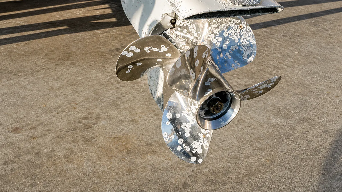
船外機プロペラはボート上の最も過酷な環境の 1 つで動作します。. 旅行のたびに砂にさらされる, 岩, 浮遊瓦礫, 浅瀬, 連続高速回転. 課題は、プロペラの損傷がゆっくりと進行することが多いことです. 今日の小さな欠けは明日には亀裂になるかもしれません, 一方で、わずかな振動が最終的にベアリングを損傷する可能性があります, シール, あるいは下部ユニットでも. 早期の警告サインを認識する方法を学ぶと、ボートの所有者が高価な修理を回避するのに役立ちます, 燃費を改善する, 水上での安全なパフォーマンスを維持します.
このガイドでは, 最も一般的なことを学びます 船外機プロペラ損傷の兆候, プロペラを正しく検査する方法, 修理が現実的になるとき, 長期的には交換がより良い解決策である場合.
プロペラ損傷の早期発見が重要な理由
パフォーマンスと効率への直接的な影響
妥協した プロペラ 船が水中で動く仕組みがすぐに悪化します. ブレードのわずかな歪みにより、エンジンが最適な負荷範囲外で動作することになります。, 全体的なパフォーマンスを低下させる.
- 破壊された流体力学: ブレードが損傷すると水の流れが変化する, その結果、最高速度が低下し、加速が弱くなる.
- 回転数制限: 変更された効果 ピッチ エンジンが指定された全開スロットル RPM に達するのを防ぎます。.
- 燃料廃棄物: プロペラの効率が低下すると、船外機の負担が大きくなります, 燃料消費量が大幅に増加.
- 振動と取り扱い: ブレードのバランスが崩れると振動が発生し、ステアリングの精度が損なわれ、全体的な乗り心地が低下します。.
二次的な機械的故障の防止
損傷したプロペラを無視すると、船外機の内部ドライブトレインにストレスが直接伝わります。. ブレードが曲がると、すぐに下部ユニットの奥深くにあるシールとベアリングが損傷します。.
- 汚れたギアオイル: 浸水フィン近くの気付かない亀裂は、水の浸入やギアオイルの汚染を引き起こすことがよくあります。.
- エンジンストレス: 変形したプロペラによりエンジン負荷が変化する, 内部コンポーネントにストレスを与える有害な回転不足または過剰回転を引き起こす.
- 疲労の加速: アンバランスなプロペラからの継続的な振動により、ギアケースのベアリングの構造疲労が加速します。, ドライブシャフト, そしてエンジンマウント.
- 過熱のリスク: 制限された取水口との組み合わせ, プロペラの状態が悪いと、深刻なエンジンのオーバーヒートが発生するリスクが高まります.
船舶の安全性と運航の信頼性
プロペラの状態が船の物理的な制御を左右します. 損傷を早期に発見できなければ、重要な操縦中に乗組員と貨物の両方が危険にさらされる.
- 突然の推進力の損失: ハブの故障が進行したり、ブレードが弱くなったりすると、負荷がかかると破損する可能性があります, 使用可能な推進力が即座に失われる.
- 衝突の危険性: ハンドリングの低下と加速の遅れにより、障害物付近での操縦性が低下します, 衝突リスクの増加.
- スケジュールの整合性: タイムリーな検出により、予定外のダウンタイムを最小限に抑えます, 商業用スケジュールの整合性を保護する, チャーター, そして救出活動.
早期介入の経済的事例
財務ロジックは単純です. 損傷したプロペラを交換すると、損傷したユニットをモーターに取り付けたままにした場合に必要な修理費の数分の一で済みます。.
- 低コストの介入: プロペラの検査と交換は、エンジンまたは下部ユニットの総修理費のほんの一部に相当します。.
- 金融出血を止める: 損傷を早期に発見することで、燃料の過剰燃焼と部品の摩耗の加速による経済的損失の増大を阻止します.
- 大規模な再構築の回避: 初期の指標を無視すると、高価なギアケースの再構築につながることがよくあります, シールの交換, そしてパワーヘッドの修理.
船外機プロペラ損傷の最初の目に見える兆候
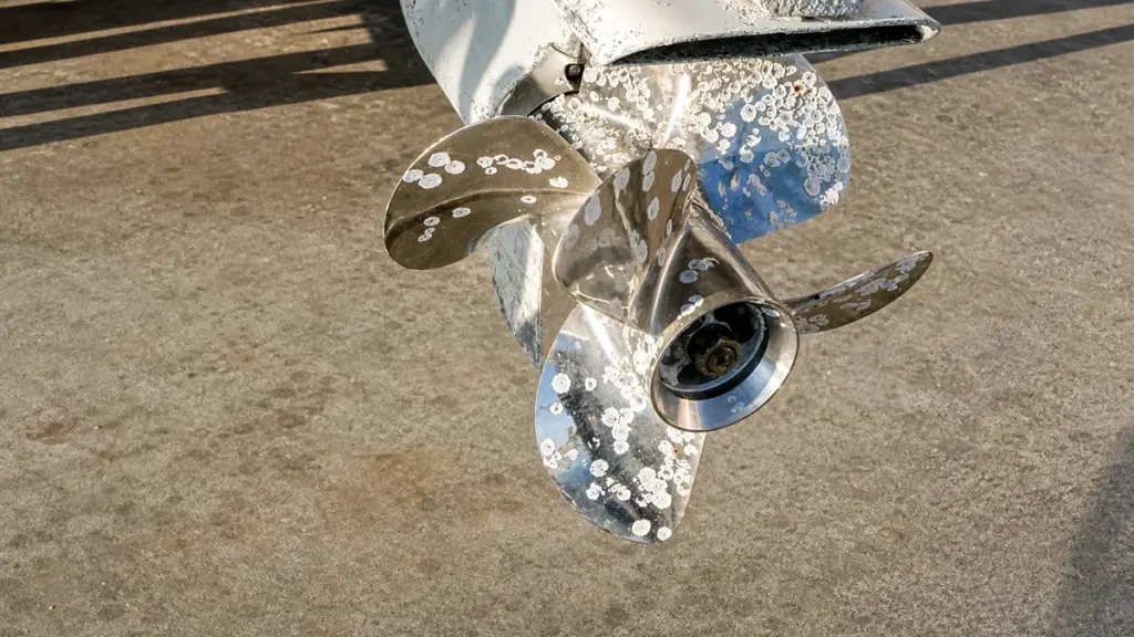
小さな傷などの船外機プロペラの損傷を早期に発見, ペイントの摩耗, またはわずかな曲がり - 燃料コストの高騰を防ぎます, 振動によるドライブトレインの摩耗, そして突然の推進障害.
塗装の劣化と表面の傷
私たちはしばしば、磨耗した塗装を通常の磨耗として無視します。, ただし、ブレードまたはハブの局所的な塗装の摩耗により、砂や小さな破片による軽度の衝撃が頻繁に発生します。. 構造的な曲がりが発生する前の最初の警告サインとして機能します。.
通常、最初に先端に細かい傷が現れることがわかります。. これらの表面摩耗は通常、より深い構造摩耗に先行して発生します。. 保護膜が剥がれると, 露出した地金パッチにより、塩水環境では腐食が促進され、直ちに脆弱性が生じます。.
ニックス, チップス, 小さなへこみ
流体力学的効率には完全に滑らかなエッジが不可欠です. 前縁に沿った小さなチップは水の流れを妨げ、キャビテーションのリスクを高めます. この乱流は圧力降下を引き起こし、周囲の金属を侵食します。.
ブレード表面の浅いへこみは、特殊な工具を使用せずに検出できる最も初期の構造変形として機能します。. 検査中は後縁をよく見てください. 後縁での早期の材料損失は、プロペラのグリップと揚力に直接影響します。, 加速と最高速度が低下します.
微妙な刃の変形や曲がり
プロペラは巨大な負荷の下で動作します, わずかな幾何学的な変化でも駆動システム全体のバランスを崩します。. わずかに曲がったブレードの先端は、以前に岩や硬い底に接触したことを明らかに示しています。.
これらの問題を特定するには, プロペラを正面から見る. 目に見える非対称性は、片側の衝撃による不均一な変形を示唆しています. 微細な反りやねじれにより、ブレード全体のピッチと荷重分布が変化します。. これにより、通常の巡航速度を維持するためにエンジンがより多くの燃料を燃焼するようになります。.
局所的な腐食とキャビテーション孔食
材料の劣化によりユニットの強度が低下します. 小さな腐食ピットまたは粉状の白い酸化物 アルミニウムプロペラ 材料が弱くなっている部分にマークを付ける. これらの斑点は放っておくとすぐに拡大します.
粗い, 高負荷領域近くのサンドブラストされたパッチは、初期のキャビテーション浸食を示しています. 蒸気の泡が金属に衝突して崩壊するとき, 彼らは表層を吹き飛ばす. 繰り返される侵食により、前縁付近の部分が徐々に薄くなります。, 高回転運転時に亀裂が発生しやすくなります。.
目に見えるハブの位置ずれとスコアリング
ハブはシフトショックを吸収し、エンジンとブレード間の重要なリンクとして機能します。. ハブカラー周囲の傷や歪みは、異常な応力または不適切な取り付けを示唆しています. 簡単な視覚診断で内部ゴムブッシュの完全性をテストできます。.
ハブとバレルを横切る直線を引きます, 負荷をかけた状態でボートを走らせる, そしてマークを確認してください. 診断マーカーのラインがずれているため、ハブ内部の滑りが視覚的に確認できます。. 平らになったエッジやピーニングされたエッジもチェックする必要があります。, 浅瀬で船外機を走らせた歴史を反映しています。, 岩だらけの水.
ソース高利益OEMガーデン & 農業機械
振動の仕方, ノイズ, 加速不良やダメージが明らかになる
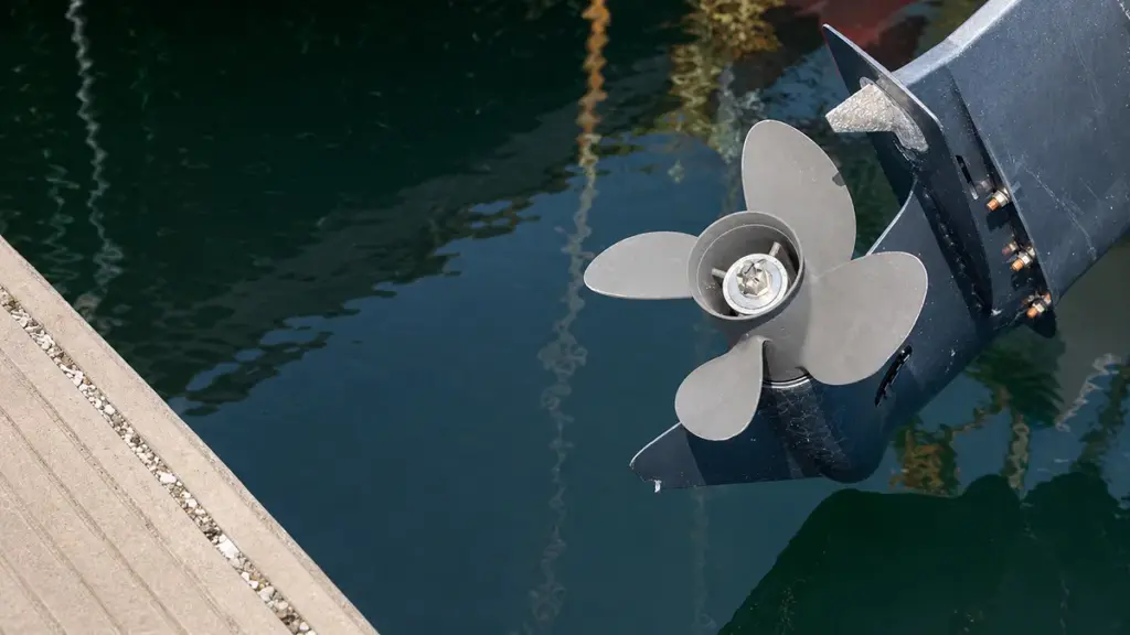
プロペラの損傷が致命的な故障として公表されることはほとんどありません. 微妙に流体力学を劣化させます, 振動による機械的警告の送信, 異音, オペレーターが解読する必要があるパフォーマンスの低下.
プロペラ誘発振動の仕組み
プロペラがわずかに損傷しただけでも、すぐに流体力学的バランスが崩れます。. ブレードが水中の物体に当たったとき, エッジが曲がったり、金属が欠けたりすると、重心が回転軸からずれます。. この機械的不均衡により、ドライブラインは周期的な応力を吸収することになります。.
- 重心移動: ブレードが曲がったり、エッジが欠けたりすると、回転軸から離れると機械的アンバランスが生じます。.
- 流体力学的歪み: ブレードの形状を変更すると揚力と推力が変化します, シャフトとギアに不均一な負荷がかかる.
- 回転数感度: 振動は、プロペラがボートを飛行機に押し込むために最も力を発揮する低回転数から中回転数でピークに達します。.
- フィードバック送信: 周期的な不均衡は、プロペラシャフトを通ってステアリングホイールに直接伝わります。, 欄間, そしてデッキ.
ノイズを特定のドライブラインの問題に変換する
船外機は負荷がかかった状態でも安定した音響プロファイルを生成する必要があります. プロペラが損傷したとき, 乱流と機械的干渉が発生し、サウンドの特徴が完全に変化します。.
- キャビテーション音: ブレードが損傷すると低圧ゾーンが発生し、キャビテーション気泡が発生します。, 独特のパチパチ音を立てる, ブザー音, またはシューという音.
- エンジンのスタッター: 不均一な推力生成により、激しい加速走行中にモーターが聞こえるようにパルスを発生させます。.
- 下部ユニットのガタつき: 衝撃力が下部ユニットに直接伝達されます, 衝撃を吸収するときにギアとベアリングが鳴る.
- 二次摩耗インジケーター: アンバランスなプロペラを長時間使用すると、プロペラシャフトのベアリングが磨耗したり、ギアケースが甲高い鳴き声を発したりすることがあります。.
パフォーマンスの低下と加速の鈍さを認識する
物理的な損傷は水中でのグリップ力を直接的に低下させます. この流体力学的非効率により、エンジンはより多くの燃料を燃焼させられる一方で、推進力は減少します。.
- プロペラのスリップの増加: 物理的な損傷により、エンジントルクが実際の前進推力に効率的に変換されなくなります。.
- 弱いホールショット: 平面への移行が遅い場合は、ブレードの歪みの主な指標として機能します。.
- 速度低下: 軽微な欠陥により最高速度が著しく低下し、特定のスロットル設定での動作 RPM が変化します。.
- ベースラインの比較: 現在の速度とスロットル全開の比較 (ウォット) 過去の指標に対する RPM により、プロペラの非効率性を実際のエンジン出力損失から分離します。.
根本原因を確認するための診断手順
純粋にオペレーターの感覚に基づいてドライブラインの問題を解決することはできません. 技術者はプロペラの損傷とエンジン内部の故障を区別するために厳格な診断シーケンスに依存しています。.
- 目視検査: 刃に曲がりがないか徹底的にチェックする, ニックス, ガウジ, ひび割れ, または不平等な海洋成長.
- シャフト試験: プロペラシャフトに目に見える曲がりがあるかどうかを確認してください, 手動回転時のバインディング, または釣り糸がアザラシに食い込む.
- 絶縁試験: プロペラを取り付けずにギアを入れてエンジンを安全に回転させ、振動が止まるかどうかを確認します。.
- 二次成分チェック: 正常なプロペラを取り付けた後も症状が続く場合は、エンジンマウントと燃料供給システムを評価する.
刃先の検査方法, ハブエリア, とシャフト接触
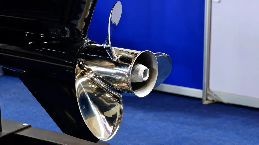
ブレード形状の体系的な検査, ハブの完全性, シャフトの接触点が下部ユニットの致命的な故障を防止します, 振動を止める, 最高の推進効率を確保します.
| 検査ゾーン | 主要な欠陥の指標 | 機能的影響 |
|---|---|---|
| 刃先 | ニックス, 内側の亀裂, 平らなカップ | 流体力学的不均衡, キャビテーション, 推力損失 |
| ハブアセンブリ | 押出ゴム, マーカー線の位置がずれている | スピンしたハブ, 負荷がかかるとドライブが完全に失われる |
| 軸 & ハードウェア | ねじれたスプライン, 磨耗したスラストワッシャー | フレッティング, ギアケースの振動, 糸ダメージ |
刃先と表面の完全性
プロペラブレードの形状は推力の生成と燃料効率を決定します. 技術者は先端を検査する必要がある, 後縁, そしてニックネームのヒント, チップ, ガウジ, または内側に放射状の亀裂. 損傷または平坦になったカップ状の後縁は、保水力を直接低下させ、早期のキャビテーションのリスクを高めます。.
- プロファイルの一貫性: すべてのブレードのすくい角とピッチが均一であることを確認して、不均一な曲げや衝撃による損傷を特定します。.
- 残高確認: プロペラをハブロッドに水平に取り付けて、重いブレードまたは面外のブレードを識別します.
- クリアランス制限: 最低限のことは確保する 3 重荷重やブレードの屈曲時の接触を防止するための、耐キャビテーション プレートからの先端クリアランス mm.
ハブ領域とスピンハブの検出
ハブはエンジンから水への激しいトルク伝達を処理します。. 損傷したゴムブッシュは故障した機械ヒューズとして機能します, 推進力を完全に落とす. 検査員はアウターハブバレルとブレードの付け根にへこみがないか確認する必要があります。, 楕円化, またはヘアラインクラック. 押し出し成形, 溶けたゴムや熱による汚れは、ブッシュの故障を明らかに示しています.
- 滑り診断: 外側ハウジング全体にマーカー線を引きます。, ラバーゾーン, そしてインナーハブ, 次に、負荷をかけてボートを走らせ、位置ずれがないか確認します。.
- 排気経路: 排気の流れを妨げる可能性のあるカーボンの蓄積や構造上の障害物がないか内部経路を検査します。.
プロペラシャフトとハードウェアの接触ゾーン
破壊的な振動がギアケースに伝わらないように、プロペラとドライブライン間の接続は完全に位置合わせされた状態を保つ必要があります。. プロペラシャフトの真直度を評価する, なくなる, さび, そして穴あきの兆候. シャフトとハブ穴の両方のスプライン歯の丸みを精密に検査する必要があります, チッピング, またはねじれたプロファイル.
- スラストワッシャーの完全性: 座面に亀裂がないか調べます, 偏摩耗, またはプロペラのアライメントを狂わせる深い溝.
- トルクの適用: メーカー指定の適切なトルクを適用します。通常は 40-60 ft-lbs—フレッチングやネジ山の損傷を防ぐため.
統合された検査ワークフロー
標準的な検査ワークフローにより、これらの個別のチェックが反復可能なプロセスに組み込まれます。. エンジンの点火を無効にする必要があります, ロック金具を取り外します, プロペラをシャフトから安全にスライドさせて外します. 古いマリン グリースで欠陥が隠れることなく、スプラインとスラスト ワッシャーを正確に評価するには、脱脂剤を使用してシャフトとハブ ボアを洗浄することが重要です。.
- コンポーネントの評価: ハブにブッシュのスピンの兆候がないか、ブレードのエッジにプロファイルの一貫性がないかを系統的にチェックします。.
- 再組み立てプロトコル: 新しいマリングリースを使用して再取り付けします, スラストワッシャーにしっかりとカチッと音がするまでプロペラを前方に押します。.
- 最終的な固定: ナットを仕様どおりに締めて、ロック金具が適切に係合していることを確認します。.
軽微な損傷がまだ修復可能な場合
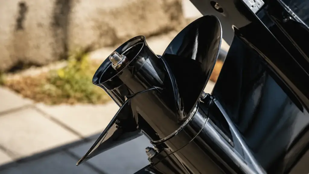
エッジのバリや浅い傷などのプロペラの軽微な損傷は、基本的なヤスリがけで修復できます。, ただし、ブレードの形状が損なわれず、亀裂や振動が存在しない場合に限ります。.
修復可能な軽微な損傷の特定
ツールを取り出す前に, 損傷が実際に軽微であることを確認する必要があります. 修復可能な欠陥は、プロペラの構造的完全性や流体力学的形状を損なわない、厳密に表面レベルの欠陥です。.
- 表面レベルのへこみ: 小バリ, 最先端のニックス, 元のブレードの形状をそのまま残す凹み.
- 孤立したエッジ摩耗: 損傷は刃先のみに限定される, つまり、全体の直径とピッチは変化しません。.
- スムーズな操作: 異常な振動を起こさず効率よく船を押し続けるプロペラ.
- 構造の健全性: 目視検査中に目に見える亀裂や物理的変形がまったくないこと.
プロペラが依然として良好に動作し、シャフトが正常に動作する場合, おそらく表面または軽微なエッジの摩耗に対処している可能性があります.
重大な損害の指標
すべての影響がすぐに解決できるわけではありません. 構造上の欠陥によっては、ギアケースを保護するために直ちに専門家の介入または完全な交換が必要になる場合があります。.
- 目に見える亀裂: ブレードまたはハブ領域の破損, 通常、専門的な溶接または交換が必要です.
- 刃の変形: 1 つまたは複数のプロペラ ブレードに顕著な曲がりやねじれがある.
- 激しい振動: 衝撃直後の揺れ, 潜在的な質量不均衡のシグナル.
- ドライブトレインへの影響: プロペラシャフトにまで及ぶ損傷, シール, または激しい打撃後のギアケース.
- ダイカストの限界: 構造上の欠陥があるダイカスト製プロペラ, 海洋専門家は日常的にこれらを修理不可能として分類しているため、.
これらの重大な欠陥がある状態で動作すると、下部ユニットのベアリングとシールに計り知れないストレスが直接伝わります。.
DIY 修理方法と規律
エッジの軽微な損傷を修正するには、正確さと慎重さが必要です. 目的は水の流れをスムーズにすることです, ブレードを再設計しない.
- プロペラを掃除する: 海洋生物をすべて除去する, ダート, 損傷プロファイルを正確に評価するためのオイル.
- フラットファイル: 目の粗いヤスリやミル野郎ヤスリをそっと使用してください。, 刃の再形成を避けるために工具を平らに保ちます.
- 除去を最小限に抑える: バリや傷を滑らかにするために必要な絶対最小限の金属のみを除去します。.
- いつ止めるべきかを知る: ブレードのバランスと効率を維持するために、隆起した金属が消えた瞬間にヤスリをやめてください。.
- エッジを磨く: やすりをかけた部分を目の細かいサンドペーパーで整えて磨き、流体力学的抵抗を減らし、腐食に耐えます。.
単一のブレードを過度にやすりで削ると重心が移動します, 単純な傷を永続的な振動の問題に変える.
修理か交換かの決断
損傷したプロペラの回収をいつやめるべきかを知ることで、費用を節約し、水上での予期せぬ故障を防ぐことができます。.
- オーナーの修理: 光だけで済む軽度のバリや小さなキズに最適, 管理されたファイリング.
- 専門店: 曲がりを直すのに必要, バランスを取る, 染料またはプローブスキャンを使用して隠れた亀裂をチェックします.
- 交換閾値: 修理費用が超過した場合の経済的な選択はより賢明です 50% プロペラの総交換価値のうち.
- スペアリカバリー: 予備のプロペラを機内に保管しておくことは、旅行中に軽微な損傷が急速に悪化した場合の究極のフェイルセーフとして機能します。.
プロペラは消耗品として扱ってください。. 新しいユニットにアップグレードすることは、アンバランスなプロペラを使用して破損したギアケースを再構築するよりも大幅に安価です.
早めの交換がより安全な選択である場合
特定の種類の損傷は、突然の故障のリスクが高まるため、修理すべきではありません。.
通常、次のような状況では交換をお勧めします。.
| ダメージタイプ | すぐに交換してください? | 理由 |
|---|---|---|
| 大きな刃の亀裂 | はい | 刃が剥がれる危険性が高い |
| 刃の部分が欠けている | はい | 深刻な不均衡 |
| 曲がったプロペラシャフト | はい | ギアボックスを損傷する可能性があります |
| 複数のブレードが損傷している | はい | 正確に復元するのが難しい |
| 重度の腐食 | はい | 構造強度の低下 |
| 繰り返されるひび割れの修復 | はい | 金属疲労は進行し続ける |
信頼性の高い船外機プロペラのパフォーマンスを実現するには NEWTOP をお選びください
耐久性のあるプロペラは信頼できる製造から始まります. で ニュートップ, 当社は、安定した性能を発揮するように設計された、精密にバランスの取れたアルミニウムおよびステンレス鋼の船外機プロペラを製造しています。, スムーズな動作, 幅広い海洋用途にわたって長寿命を実現.
当社の製造プロセスは高度なCNC機械加工を組み合わせています。, 厳密な寸法検査, 動的バランシング, すべてのプロペラが出荷前に一貫した性能基準を満たしていることを確認するための包括的な品質テスト. アフターマーケット流通または自社ブランドの OEM 生産のために交換用プロペラが必要かどうか, NEWTOPは信頼性を裏付けた柔軟な製造ソリューションを提供します 生産能力 世界的な輸出経験.
主な利点は次のとおりです。:
- CCSおよびECE認定の品質 信頼性の高いパフォーマンスと国際市場の要件に対応.
- プレミアム素材 — アルミニウム製プロペラは、高強度と靭性を実現するために特別に配合されたアルミニウム - マグネシウム合金を使用しています。, 一方、ステンレス鋼プロペラは降伏強度と耐食性に優れた二相ステンレス鋼を使用しています。.
- 一体成形技術 — プロペラブランクは溶接なしで専用の金型で成形されます, 構造強度と耐久性の向上.
- 精密ハブプレスとCNC加工 — 一体型プレスハブによりダイナミックバランスが向上, CNC 加工されたブレードにより、一貫した形状と安定した推力性能が保証されます。.
卸売供給またはカスタマイズされた生産を行う、信頼できる船外機プロペラ メーカーをお探しの場合, 今すぐNEWTOPに連絡してください. 当社のエンジニアリングおよび生産チームは、一貫した品質と長期供給を確保しながら、お客様の市場に適したプロペラ ソリューションの選択をお手伝いする準備ができています。.
よくある質問
船外機プロペラが損傷しているかどうかを確認するにはどうすればよいですか?
目に見える曲がりを探す, チップ, ひび割れ, またはブレード上の材料が欠けている. 船の加速が比例せずに、エンジンの回転数が異常に高くなるなどの動作兆候が見られます。, 多くの場合、これは回転したハブを指します. 持続的な振動に気づく場合もあります, 金属音, または通常の巡航速度での操縦安定性の損失.
プロペラの小さな傷は振動を引き起こす可能性がありますか?
はい, 小さな傷でもブレードの質量分布と流体力学的対称性が変化します。. この物理的な不均衡により、顕著な振動として現れる遠心力が発生します。, 多くの場合、特定の RPM 帯域内にあります. 軽微な損傷を無視すると、プロペラシャフトと下部ユニットのベアリングの摩耗が進行します。.
スピンしたプロペラハブはどんな感じですか?
回転したハブはボートが水の中で滑っているように感じます. スロットル下でエンジン回転数が急激に上昇する, しかし船の速度は上がらない. これは自動車のクラッチが滑る感覚を模倣しており、突然推力が失われたり、ゴムの焦げたような臭いを伴うことがあります。.
欠けたプロペラは修理または交換した方がよいでしょうか?
エッジの小さな欠けや小さな曲がりは通常、修理が可能です, 特に高価なステンレススチール製支柱の場合. プロペラに大きな欠けがある場合は交換します。, 根元近くの深い亀裂, または、修理費用が新品交換の半額を超える低コストのアルミニウムユニットを使用している場合.
プロペラの損傷により燃費が低下する可能性があります?
ブレードが損傷すると、流体抵抗が増大し、スムーズな水の流れが妨げられます。, 速度を維持するためにエンジンにさらに負荷をかける. この機械的非効率により、モーターが最適な RPM 帯域で動作できなくなります。, 直接的には 1 海里あたりの燃料消費量が増加します.
プロペラが損傷するとどのような騒音が発生しますか?
通常、プロペラが破損すると、エンジン回転数と同期してリズミカルなノッキング音やドスンという音が発生します。. また、金属的なカタカタ音や耳障りな音が聞こえる場合もあります。, 下部ユニットからの低周波ドローン, 特に急加速時や急旋回時.
プロペラが曲がったままボートを走らせることはできますか?
プロペラが曲がったボートは、安全にドックに戻るために最小限のアイドル出力でのみ操作してください。. アンバランスなブレードでプレーニング速度で走行すると、プロペラシャフトをすぐに破壊する重大なラジアル荷重が発生します。, ベアリング, およびギアケースシール.
プロペラはどのくらいの頻度で検査すべきですか?
走行の前後に簡単な視覚的および触覚的チェックを実行して、明らかな曲がりを見つけます, チップ, または巻いた釣り糸. 完全な取り外し検査を完了します。プロペラを取り外してシャフトを確認します。, シールを検査する, 少なくともシーズンに 1 回、または 1 年に 1 回はスプラインにグリースを塗り直してください。 100 営業時間.
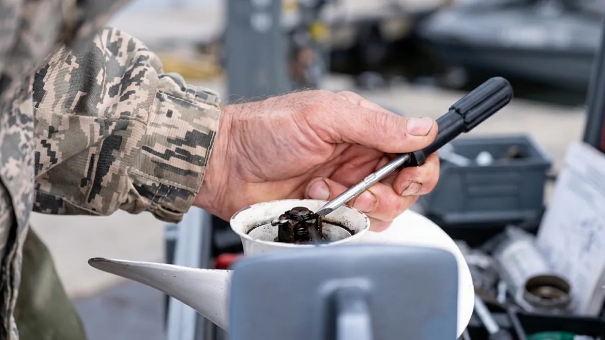
多くのボート所有者は、ボートの感触が変わるまでプロペラの損傷に気づきません。. もしかしたら加速が遅くなるかもしれない, 燃料費が増加する, または、隠れた岩や浮遊する破片に衝突した後、ステアリングホイールが振動し始める. 早期の警告サインを知ることで、高額な修理を回避し、船外機を効率的に稼働し続けることができます。.
このガイドでは, について説明します 5 損傷の最も一般的な兆候 船外機プロペラ, なぜそれらが重要なのか, プロペラを交換する時期が来たとき.
損傷したプロペラを決して無視してはいけない理由
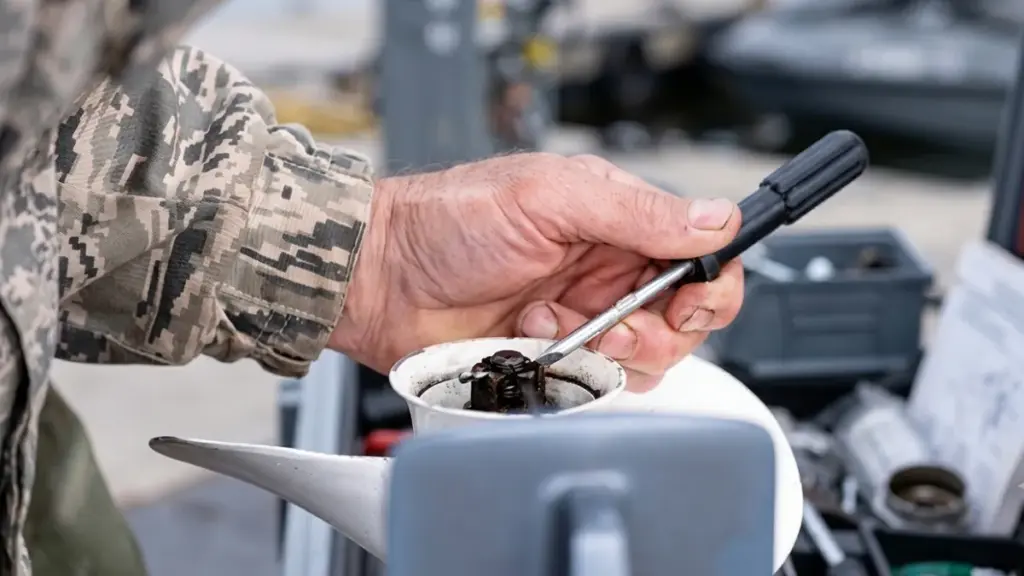
損傷したプロペラを無視すると、軽度の効率損失が深刻なギアケースの損傷につながります, 燃料費の高騰, 危険な取り扱いの問題. エンジンと財布を守るために早めに修正してください.
パフォーマンスの低下と処理の問題
プロペラが損傷すると、ボートの設計上の性能が即座に失われます。. ブレードのわずかな歪みでも、エンジン出力を効率的な前進運動に変換するために必要な流体力学的プロファイルを台無しにしてしまいます。. オペレーターは通常、これをホールショットの鈍さや最高速度の顕著な低下として認識します。.
- 推力損失: ブレードが曲がったり欠けたりすると、形状が崩れます, 前方への推力が減少し、加速が悪くなる.
- ハンドリングの不安定さ: 不規則なブレード表面により不均一な推力が発生, ステアリングの引きにつながる, 不安定なトリム, 一貫性のない追跡.
- 振動の発生: 回転バランスが崩れると負荷がかかると振動が発生する, プレーニング速度でデッキをリズミカルにドスンという音として感じることがよくある.
燃料消費量と運転コストの増加
問題のあるプロペラを使用すると、運用予算が直接攻撃されます。. ブレード表面の欠陥により層流が破壊されます, それを抗力と乱流に置き換える. 標準巡航速度に達するだけでも、エンジンはかなり多くの燃料を燃焼する必要があります.
- ドラッグの追加: 損傷したブレードは乱流を誘発します, 勢いを維持するためにエンジンにさらに負荷をかける.
- 燃料燃焼量の増加: プロペラが汚れたり曲がったりすると、日常的に全体の燃料消費量がおよそ増加します。 10%.
- スロットル補正: オペレーターは非効率な推力を相殺するために自然にスロットルをより強く押します。, 日々のランニングコストを静かに増大させます.
下部ユニットに重大な機械的ストレスがかかる
外側の表面的な損傷には、内側の深刻な機械的破壊が隠れていることがよくあります. アンバランスなプロペラはドライブトレインに対してハンマーのように作用します. 定数を送信します, 周期的なストレスを下部ユニットに直接伝達, 安価なプロップの修正を大規模なギアケースの再構築に変える.
- ギアケースの摩耗: 不均一な荷重により応力が下部ユニットに直接伝わります。, 歯車を破壊する, ベアリング, そしてシャフトが時期尚早に.
- シールの劣化: 持続的な振動によりプロペラシャフトのシールが破壊される, ギアオイルが漏れて水が浸入する可能性があります.
- 軸の芯ずれ: ブレードを変形させる強い衝撃によりプロペラシャフトが頻繁に曲がる, チェックしないままにしておくと致命的な障害が発生することが保証されます.
安全上のリスクと座礁の可能性
破損したプロペラを使用して操作すると、安全マージンがレッドゾーンに押し込まれます. クリーンな推力が失われると、狭い空間や荒れた状況では船が予測不能になります。. 損傷したドライブトレインを沖合に押し出すと、最も電力が必要なときに突然の機械故障が発生します。.
- ドッキングの危険性: 逆推力の喪失と不安定なハンドリングにより、狭い水路やスリップでの操縦制御が失われます。.
- 故障リスク: すでに損傷がある状態で走行すると、走行中に突然の機械故障が発生する可能性が大幅に高まります.
- 天候による脆弱性: 推進効率の低下により、荒れた海を航行する際の安全マージンが損なわれます, 強風, または強い流れ.
5 船外機プロペラの損傷の兆候リスト
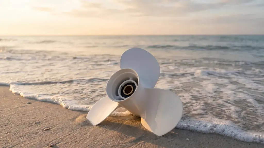
船外機が突然振動した場合, 速度が失われる, または通常より多くの燃料を消費する, プロペラはすでに損傷している可能性があります. 以下の表は、最も一般的な症状をまとめたものです, 考えられる原因, そしてそれらがエンジンにどのような影響を与えるか.
| 警告標識 | 主な原因 | 差し迫ったリスク |
|---|---|---|
| 振動 | 曲がったブレードまたは緩んだハブ | ギアケースのシール不良 |
| 速度低下 / ホールショットが悪い | 回転したハブまたはブレードの抵抗 | エンジンの荷物 |
| ノイズ / ステアリングが不安定になる | 非対称ブレードまたは曲がったシャフト | ロアユニットギアの損傷 |
| 燃料の使用量が多い / 負荷 | 流体抵抗 | ピストンと冷却システムの摩耗 |
| 目に見えるダメージ | 衝撃攻撃 | ドライブトレインへの衝撃荷重 |
サイン 1: 加速時や巡航時の振動
損傷したプロペラが実際に回転することはほとんどありません. ハンドルを通して直接感じられる揺れに気づくでしょう, 船外機ハウジング, またはボートの船体自体, 特に加速時や一定の巡航速度を維持しているとき. この振動はプロペラの効率を大幅に低下させ、エンジンマウントやギアケースのシールに即座にストレスを与えます。.
- 一般的な原因: 刃が曲がったり歪んだりする, 緩んだハブ, またはプロペラシャフトの周りに汚れた重い破片.
- 実用的なチェック: エンジンを止めてプロペラを点検してください. ブレードの角度を見て、それらが一致していることを確認します, 次にプロペラを手で回転させて、ギヤケースに対するぐらつきや擦れを見つけます。.
サイン 2: スピードの低下とホールショットの悪さ
鈍い加速, 飛行機に乗るまでの時間が著しく遅くなる, 推進力の非効率に直接影響する最高速度ポイントの減少. エンジン回転数が正常または高いままであっても, プロペラが損傷すると、そのパワーを前方への推力に変換できなくなります。. これは多くの場合、損傷したブレードエッジの周囲のキャビテーションや過剰な抗力を生み出す激しい海洋汚染によって発生します。.
- スピンハブインジケーター: インナーブッシュが故障した場合, エンジンのトルクをフルに水に伝えることができません, 最小限のボートの動きで高回転を引き起こす.
- 実用的なチェック: 現在の全開スロットルを比較してください (ウォット) 船舶の過去のベースライン データに対する RPM と最高速度.
サイン 3: 異音やステアリングの不安定さ
新しいハミング, ガタガタ, または、研磨音が発生する場合は、重大な機械的ミスアライメントが発生していることを示します。, 特に旋回時や特定の RPM 範囲を通過するとき. また、舵が操縦しにくくなったり、片側に大きく引っ張られるように感じられる場合もあります。. 非対称だからこうなる, 曲がったブレードは不均一な推力を生成します, ボートを自然な航路から外そうとする.
- ギアケースの脅威: 継続的な研磨は、通常、プロペラシャフトが曲がっているか、以前の水中での衝撃による下部ユニットのギアの損傷を示しています。.
- 実用的なチェック: プロペラを前後に小刻みに動かし、過剰な遊びを検出します. 手で回して内部のこすれる音がないか注意深く聞いてください。.
サイン 4: 燃料使用量の増加とエンジンの異常負荷
燃料効率が突然低下するということは、まったく同じルートと荷物を運ぶために燃料ドックに頻繁に立ち寄ることになるということです。. ブレードの損傷や汚れによる流体抵抗により、失われた推力と振動を克服するためにエンジンがさらに激しく動作することになります。. エンジンの音が緊張し、通常の巡航速度を維持するにはより高いスロットル設定が必要になります。.
- 長期間の着用: このような高負荷条件下で継続的に運転すると、ピストンの摩耗が加速します。, ベアリング, および船外冷却システム.
サイン 5: 目に見える刃, ハブ, またはエッジダメージ
物理的欠陥は影響を示す最も明白な指標です. 簡単な目視検査で傷が見つかることがよくあります, ヒントです, 不足しているチャンク, またはヘアラインクラック. これらの欠陥は通常、ボートの座礁や岩への衝突によって発生します。, 砂州, サンゴ礁, または水没した瓦礫. たとえ軽微な物理的損傷であっても、プロペラの実効ピッチとバランスが変化します。, 有害な衝撃荷重を下部ユニットに直接伝えます。.
- 実用的なチェック: プロペラを取り外してすべての表面を詳しく検査します. 重大な構造的損傷が見つかった場合、または修理見積もりが超過した場合は、ユニットを交換してください。 50% 新しいプロップの費用.
高性能 OEM 船外機プロペラの供給元

適時に適切なプロペラを交換してエンジンを保護する方法
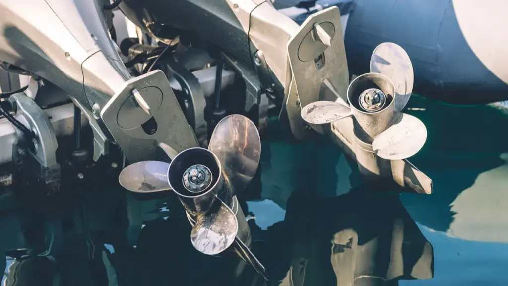
プロペラが損傷すると、エンジンの動作がさらに激しくなり、ドライブトレインに重大な障害が発生する危険性があります。. 故障したユニットをすぐに交換すると、ギアケースが保護され、ベースラインの燃費が回復します。.
交換時期の特定
プロペラの交換時期を正確に把握することで、軽度の摩耗が機械的故障に発展するのを防ぎます。. 視覚的および触覚的検査は防御の第一線として機能します. 水没した物体に衝突した場合は、直ちに対処する必要があります, 船がまだ動いていても.
- 目に見える構造上の損傷: 深い亀裂がないか確認する, 大きな欠落したチャンク, ひどく曲がった刃, またはブレードの形状を損なうエッジの薄化.
- ベースラインのパフォーマンスが低下する: エンジンが突然ベースラインの全開スロットルに達しなくなることに注意してください。 (ウォット) 通常負荷時の RPM または最高速度.
- 振動と取り扱いの問題: 持続的な振動, ステアリングプル, または粗いトラッキングはプロペラのバランスが崩れていることを示します.
- 衝撃後の検証: 水中の岩にぶつかった後は、必ずプロペラを取り外してシャフトとシールを検査してください。, ログ, または瓦礫.
適切な交換用プロペラの選択
適合しないプロペラを取り付けることは、壊れたプロペラを使用するのと同じくらい有害です. 交換仕様を船体のタイプおよび一般的な動作荷重に合わせて調整する必要があります.
- 正しいピッチと直径: メーカーの推奨ピッチ範囲を逸脱すると、エンジンがオーバーレブまたはラグになります。, 燃費と加速を破壊する.
- 衝撃吸収のためのアルミニウム: アルミニウム製の支柱は浅いところでは犠牲的なバリアとして機能します。, 危険が密集した水域. 衝撃を受けると変形します, 高価なギアケースに伝わる衝撃がはるかに少ない.
- 耐久性に優れたステンレススチール: 最大の効率が必要な場合はステンレス鋼を選択してください, 耐屈曲性, 深海または危険のない水域での耐久性.
設置および交換後の確認
交換を成功させるには、ハブ アセンブリとシャフトの環境に細心の注意を払う必要があります。. 新しいプロペラをスライドさせる前に, ドライブラインが正しく機能するように、エリアを徹底的に清掃して準備します。.
- シャフトの準備: 巻かれた釣り糸を剥がす, 雑草, 新しいシールを切り込む可能性のある破片.
- ハードウェアシート: スプラインにマリングレードのグリースを塗布します. プロペラナットを締めすぎずに正確なトルク仕様に固定します。, 設計で必要な場合は、新しい割りピンを挿入します.
- 摩擦試験: 船外機をニュートラルにシフトし、新しいプロペラを手で回転させます. ギアケースを拘束したり擦ったりすることなく、自由に回転する必要があります.
- ベースライン検証: 通常の負荷でボートを走らせ、新しいプロペラが元の最高速度と WOT RPM を回復することを確認します。.
結論
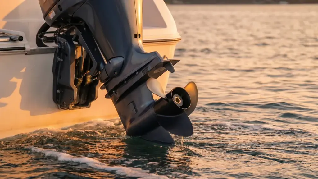
定期的な点検と適時の交換が船外機を保護する最善の方法です, ボートのパフォーマンスを向上させる, 長期的な運用コストを削減します. 正しいピッチの船外機プロペラを調達することも同様に重要です。, 直径, 信頼性の高い効率的な動作を保証する高品質の素材.
自社のフリートのプロペラを交換する場合でも、ビジネス用の製品を調達する場合でも, 経験豊富な船外機プロペラメーカーと提携することで、製品の品質に大きな違いをもたらすことができます, パフォーマンス, そして長期的な信頼性. で ニュートップ, 当社の統合船外機プロペラ工場は、高度な製造と柔軟な OEM/ODM サービスを組み合わせて、代理店や船舶ブランドが競争市場で成功できるよう支援します。.
👉 NEWTOPに今すぐ連絡してください OEM または卸売の要件について話し合い、次の船外機プロペラ プロジェクトの競合見積もりを受け取ります。.
よくある質問
船外機プロペラの損傷の兆候は何ですか?
視覚的な欠陥によってプロペラの損傷を見つけることができます, パフォーマンスが低下する, そして機械的な症状. へこみを探す, 刃先です, 不足しているチャンク, またはハブ付近のヘアラインクラック. 水の上で, ダメージは最高速度の低下として現れる, 鈍いホールショット, エンジンの回転数が高く、ボートの前進速度が低い. また、舵に新しいリズミカルな振動を感じたり、ドスンという音が聞こえる場合もあります。. ロアユニット周辺に白濁したギヤオイルが漏れていることに気づいたら, 衝撃によりプロペラシャフトのシールが損傷した可能性があります.
プロペラが損傷するとエンジンが損傷する可能性があります?
はい, プロペラが損傷すると、船外機全体と下部ユニットに大きなストレスがかかります。. ブレードのわずかな曲がりでも回転バランスが崩れます. この回転アンバランスにより、連続的な, ドライブラインに直接伝わる激しい振動. チェックを外したままにする, この揺れにより、プロペラシャフトシールが壊れるまで叩き込まれます。, ギアの潤滑油が漏れて水が流入する. この状態でエンジンを運転すると、ギアセットやベアリングに破壊的な金属間の摩耗が急速に発生します。.
水中で何かにぶつかるとボートが振動するのはなぜですか?
水没した物体に衝突するとドライブトレインのバランスが崩れます. 通常、衝撃によりプロペラブレードが曲がります。, 材料を切り落とす, またはプロペラシャフトをわずかに曲げます. プロペラが対称的な形状を保てなくなったり、完全に正しく回転したりしないためです。, スムーズに回転するのではなく、周回します. このぐらつきがリズミカルな揺れの力を生み出し、それが外側の脚に伝わります。, エンジンマウントを通して, そして船体に直接.
プロペラの損傷により加速が悪くなる可能性があります?
はい. 物理的ダメージによりブレードのピッチが変化する, キャンバー, そしてカップ. この歪みによりプロペラの流体力学的効率が損なわれます。, 水面でのグリップを強制的に失い、前方への推進力が大幅に減少します。. また, 強い衝撃により内側のゴム製ハブが損傷した場合(一般に「傷」と呼ばれます) “スピンしたハブ”—プロペラシェルがシャフト上で滑る. スロットルを踏むと, ボートがほとんど加速しない、または飛行機に乗るのに苦労しているのに、エンジンが高回転する.
プロペラが不良だと燃料消費量が増加しますか?
はい. 損傷したプロペラを作動させると、エンジンは 1 マイルあたりにより多くの燃料を消費することになります。. 曲がった, 欠けた, または、ひどく汚れたブレードは余分な流体力学的抵抗を生み出し、プロペラのスリップを増加させます. 損傷したブレードはエンジントルクを効率的に推力に変換できなくなるため, 通常の巡航速度を維持するために、船外機はより速く回転し、より懸命に働かなければなりません. 季節を越えて, この非効率性により、燃料代が大幅に増加します.
損傷したプロペラはどのくらいの期間安全に使用できますか?
損傷したプロペラは、低速でドックに戻るのに十分な時間だけ運転してください。. 振動を操作する, アンバランスなプロップを長期間使用すると、異常な状態になります。, 下部ユニットのベアリングとシールにかかる周期的なストレス. この状態でエンジンを始動すると、単純な問題が急速にエスカレートします。, 安価なプロペラ交換から壊滅的なギアケースの再構築まで.
ハブが損傷するとエンジンが過剰回転する可能性があります?
はい. メーカーは、下部ユニットのギアをせん断から保護するために、激しい衝撃時に滑るように内側のゴム製ハブを設計しています。. このハブが回転したり破れたりすると, プロペラの外側シェルに対するしっかりとしたグリップが永久に失われます。. スロットルをかけると, 損傷したハブはトルクを伝達せずにスリップします. これにより、ボートを前に押し出すことなく、エンジン回転数を急速に上昇させることができます。, トランスミッションのスリップ感を模倣する.
予備のプロペラを機内に置いておくべきですか?
予備のプロペラを機内に保管しておくことを強くお勧めします. 安い保険の役割を果たします, 特にアルミニウム製のプロップを使用したり、定期的に浅い場所を航行したりする場合は、, 障害物で満たされた水域. 予備ユニットの持ち運び, プロペラレンチと一緒に, 交換用スラストワッシャー, そして新しい割りピン, 破損したプロップをその場で交換できます. これにより、安全な推進力がすぐに回復し、台無しな週末や高額なレッカー費用を節約できます。.
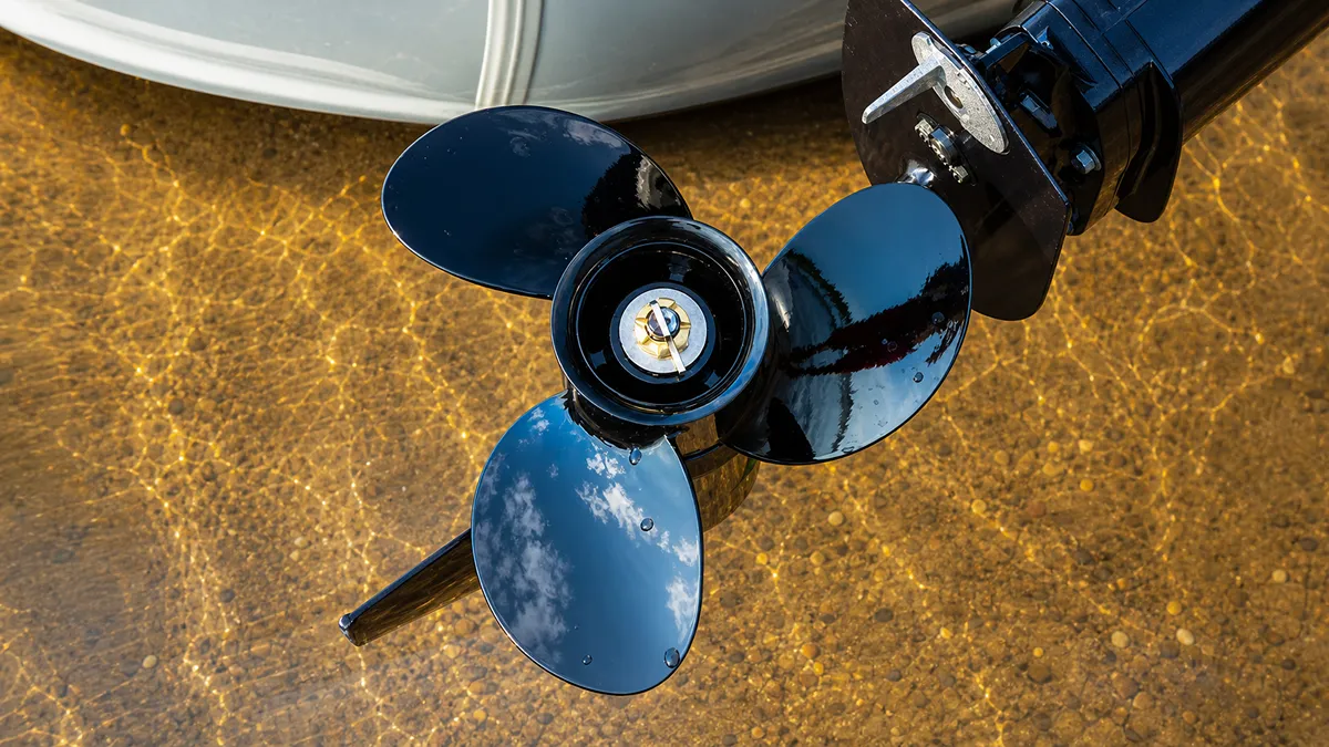
When a boat suddenly loses thrust, engine RPM rises without matching acceleration, or the プロペラ shows unusual surface damage, many operators assume the propeller is simply worn out. 実際には, the problem may be propeller cavitation.
Cavitation is one of the most misunderstood issues affecting outboard motor performance. It reduces efficiency, increases fuel consumption, shortens propeller life, and may even lead to expensive repairs if ignored. Although it is often confused with ventilation, the two problems have different causes and require different solutions.
このガイドでは, we’ll explain what cavitation is, what causes it, how it affects your boat, and the practical ways to prevent it by choosing the right propeller and setup.
What Is Cavitation in Outboard Motor Propellers?
Cavitation in outboard propellers is a destructive hydrodynamic pressure issue. Vapor bubbles form and violently collapse on the blades, causing power loss and severe metal erosion.
The Physical Process of Cavitation
Cavitation starts when rapid propeller rotation forces local water pressure to drop below its vapor pressure. This extreme low pressure triggers an immediate phase change, creating vapor bubbles directly on the blade surface. The water essentially boils at ambient temperature due to the pressure drop.
As the spinning propeller drives these vapor bubbles into higher-pressure zones, they cannot sustain their form and collapse violently. These collapsing bubbles release intense micro-shock waves against the blade. 時間とともに, these repeated impacts pound the metal surface, eroding the material and causing severe pitting.
Common Causes in Outboard Setups
Several setup and operational factors create the ideal environment for these damaging low-pressure zones to form.
- Incorrect mounting and trim: Setting the engine mounting height too high or trimming the motor out too far disrupts solid water flow across the blades.
- Poor propeller selection: Using a propeller poorly matched to the boat’s hull, load, or engine power forces the blades to carry excessive hydrodynamic load.
- Pre-existing damage: Bent blades, over-filed tips, or nicked edges create uneven hydrodynamics that trigger localized pressure drops.
- Disturbed inflow: Hull turbulence, transducers, or underwater obstructions prevent clean water from reaching the lower unit.
Symptoms and Performance Impacts
Operators usually identify cavitation through immediate handling degradation and eventual mechanical wear on the propulsion system.
- Loss of thrust: You experience a sudden decrease in power transfer efficiency, leaving the boat feeling sluggish under heavy throttle.
- RPM flaring: The engine speed surges rapidly without a proportional increase in forward acceleration.
- Audible disturbances: Collapsing bubbles create a distinct gravel-like rattling, accompanied by excessive vibration through the transom.
- Cumulative wear: Unchecked cavitation leads to visible blade erosion, pitting, and structural metal fatigue over time.
Distinguishing Cavitation from Ventilation
Boaters frequently confuse cavitation with ventilation, but they are entirely different mechanical events. Cavitation functions strictly as a hydrodynamic pressure issue resulting in vaporized water. Ventilation happens when the propeller physically pulls surface air or exhaust gases directly into the slipstream.
Both phenomena create nearly identical operator symptoms, including sudden RPM flare and an immediate loss of bite in the water. Accurate diagnosis dictates the repair path. Fixing ventilation usually involves basic trim adjustments or dropping the engine height. Resolving cavitation often requires repairing damaged blade edges or selecting a completely different propeller design to handle the engine’s output.
How Cavitation Differs from Ventilation
Cavitation is a pressure-induced phase change causing water to boil and erode propeller blades, while ventilation is external air getting sucked into the prop wash, causing sudden slippage.
Many boat owners use the terms キャビテーション そして ventilation interchangeably, but they describe two different phenomena.
| 特徴 | Cavitation | Ventilation |
|---|---|---|
| Cause | Water pressure drops below vapor pressure. | Air enters the propeller blades. |
| Medium Around Blade | Water vapor bubbles. | Air from above the water surface. |
| Main Symptom | Blade erosion and reduced propulsion efficiency. | Sudden engine RPM increase with poor thrust. |
| Blade Damage | はい, often causes pitting and surface erosion. | Usually no direct blade erosion. |
| Typical Causes | Incorrect blade loading, damaged propeller, poor blade design, or excessive pressure drop. | Engine mounted too high, sharp turns, rough water, or excessive trim angle. |
A simple way to remember the difference:
- Cavitation creates bubbles from water.
- Ventilation pulls air into the propeller.
Maximize Margins With Professional-Grade Garden Machinery
The Main Causes of Propeller Cavitation
Cavitation occurs when local water pressure drops below vapor pressure. Excessive speed, mismatched propellers, blade damage, and disturbed inflow from poor setup are the primary triggers.
| Cavitation Cause | Primary Mechanism |
|---|---|
| スピード & Loading | High RPM and heavy vessel loads drive local pressure below the vapor threshold. |
| Propeller Mis-Match | Wrong pitch or physical size creates extreme pressure imbalances across the blade. |
| Blade Damage | Nicks and bent edges prevent smooth water flow, causing localized low-pressure zones. |
| Setup & Inflow | Improper engine height or hull obstructions introduce turbulent, low-pressure water. |
Excessive Propeller Speed and High Loading
Propellers designed for standard operation struggle when pushed past their hydrodynamic limits. Spinning a blade too fast creates an extreme pressure drop on the back side. This sudden vacuum forces the water to vaporize instantly into gas pockets.
Operating parameters heavily influence this pressure shift. Specific stressors force the propeller into a continuous cavitation cycle.
- Heavy loads: Excess vessel weight forces the engine to work harder, multiplying blade stress.
- Hard acceleration: Rapid throttle spikes disrupt steady water flow and immediately drop local pressure.
- Extreme RPMs: Sustained high-speed operation with an overloaded vessel guarantees continuous vapor formation.
Incorrect Pitch, Sizing, and Propeller Mis-Match
Slapping any available propeller onto an outboard guarantees poor performance. Pitch directly dictates blade loading. Excessive pitch bogs down the engine and overloads the blades at lower speeds. Insufficient pitch lets the engine over-rev, accelerating the blades so fast that they tear the water apart and induce surface cavitation.
Proper matching requires aligning the propeller geometry with the specific vessel dynamics to maintain pressure equilibrium.
- Diameter constraints: Selecting a size that ignores hull weight and horsepower creates severe pressure imbalances.
- Blade geometry: The wrong blade count, rake, or cup strips the propeller of its grip, increasing slip and flow separation.
- 船体の互換性: A propeller style mismatched to the hull design fails to handle the specific water flow of that vessel.
Physical Blade Damage and Surface Imperfections
Water requires a perfectly smooth surface to maintain laminar flow. Minor impact damage alters the local hydrodynamics completely. ニックス, ガウジ, or missing chunks on the leading edge stop the blade from slicing cleanly. These defects act as turbulence generators, spawning localized low-pressure zones where vapor bubbles rapidly form.
Physical irregularities consistently trigger flow breakdown across the entire propulsion system.
- Bent blades: Asymmetric geometry causes uneven loading and violent pressure swings during every revolution.
- Altered edges: Overly sharpened or blunt leading edges detach the water flow prematurely.
- Lower unit fouling: Barnacle buildup or deep scratches on the gearcase destroy the clean water stream before it reaches the blades.
Disturbed Inflow, Setup, and Clearance Issues
A propeller operates efficiently only when fed a steady stream of dense, clean water. Mounting the outboard too high on the transom starves the system. This setup places the blades near the surface where the water is already aerated and low in pressure, accelerating the phase change into vapor.
Environmental factors around the transom dictate the quality of the inflow reaching the propeller.
- Clearance limits: Inadequate spacing between the propeller, hull bottom, and skeg amplifies local turbulence.
- Appendage drag: Poorly placed transducers or water pickups inject chaotic currents directly into the propeller path.
- Vessel attitude: Excessive stern weight or improper boat trim shifts the inflow angle, severely degrading water density.
How Cavitation Affects Speed, Fuel Use, and Blade Life
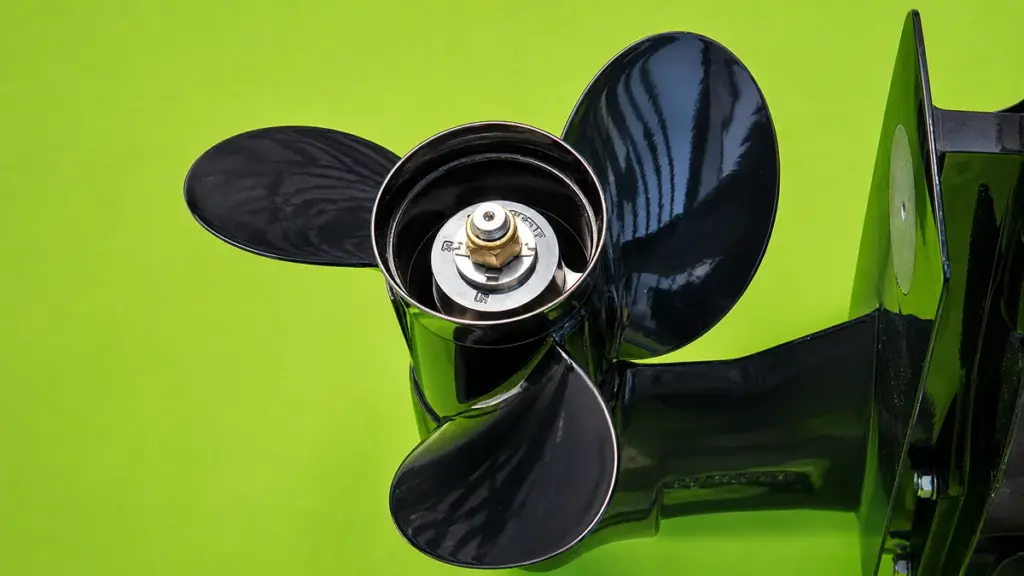
Cavitation cripples propeller efficiency. It kills top speed, burns up to 10% more fuel per mile, and destroys blades through violent micro-shock waves, forcing expensive premature replacements.
Impact on Boat Speed and Acceleration
When cavitation vapor bubbles form, they reduce effective blade lift. This breaks the propeller’s physical hook-up to the water and causes a massive drop in thrust. You will often feel this as a sudden RPM flare with barely any forward movement, forcing you to back off the throttle to let the blades regain bite.
- Hole-Shot Performance: Acceleration becomes sluggish, drastically extending the time it takes to get the heavy hull on plane.
- Top Speed Penalty: Even partial tip cavitation creates enough drag to cause a 2–5% loss in top speed on high-performance setups.
Increased Fuel Consumption and Reduced Efficiency
Vapor bubbles sticking to the blade surfaces act like a physical barrier. They increase friction and alter the effective thickness of the blade, destroying hydrodynamic efficiency. To compensate for the lost thrust, operators push the throttle further forward. This pushes the engine into a higher RPM band where it operates far outside its peak fuel efficiency range.
- Burn Rate: A chronic cavitation mismatch burns 5–10% more fuel per mile just to maintain the same hull speed.
- Lifetime Waste: Over the lifespan of a commercial or high-use outboard, this hydrodynamic drag wastes hundreds of gallons of fuel.
Structural Damage and Shortened Blade Life
Cavitation acts as a mechanical grinder on your hardware. When vapor pockets move into higher-pressure water, they collapse violently. These implosions generate localized micro-shock waves that mechanically hammer the metal, leading to severe pitting along the leading edges and low-pressure faces of the propeller.
- Vibration and Fatigue: The uneven collapse of bubbles creates high-frequency vibrations, subjecting the prop to continuous high-cycle fatigue.
- Cracking and Separation: Fatigue promotes micro-cracking at critical stress points like root fillets, which can quickly progress into complete blade separation under heavy loads.
- Collateral Damage: The constant oscillatory loads force premature propeller replacement and increase the risk of catastrophic bearing and seal failures inside the lower unit.
How to Fix Cavitation Through Setup and Prop Selection

Most slipping issues are actually ventilation. Fixing engine height, adjusting trim, and selecting a cupped stainless-steel propeller will quickly restore grip and stop performance loss.
| 解決 | Benefit |
|---|---|
| Repair Damaged Blades | Restores smooth water flow and improves propulsion efficiency. |
| Select Proper Pitch | Reduces blade overload and helps maintain optimal engine RPM. |
| Choose Correct Diameter | Improves thrust distribution and overall propulsion performance. |
| Adjust Engine Mounting Height | Optimizes water flow to the propeller and reduces pressure fluctuations. |
| Correct Trim Angle | Improves blade loading and enhances propulsion efficiency. |
| Clean Hull Regularly | Restores smooth water flow by eliminating marine growth and surface drag. |
| Balance the Propeller | Reduces vibration, uneven loading, and pressure imbalance. |
| Upgrade Propeller Design | Improves hydrodynamic efficiency and minimizes the risk of cavitation. |
Differentiating Ventilation from Cavitation
Operators often blame cavitation when their propeller loses grip. 実際には, most slipping issues are actually propeller ventilation. This happens when the blades pull in surface air or exhaust gas instead of solid water. True cavitation is a hydrodynamic pressure problem where extreme low pressure forms vapor bubbles on the blade surface. It is far less common in everyday troubleshooting.
Both conditions share identical symptoms on the water. You will experience the following performance drops:
- Rising RPMs: Engine speed flares without a proportional increase in boat speed.
- Loss of thrust: The propeller suddenly drops its grip on the water.
- Slipping: Forward momentum stalls during hard acceleration or tight turns.
Optimizing Engine Height and Trim
A poorly adjusted outboard is the leading cause of poor propeller bite. Start your troubleshooting by testing the boat with the trim fully down to establish a performance baseline. Adjust the trim up slightly to find your usable running range. If the propeller still breaks loose, lower the engine mounting position on the transom. This keeps the anti-ventilation plate deeper in the water, blocking surface air from reaching the blades.
You should also trim down when entering tight turns so the propeller stays submerged as the hull leans. ついに, inspect the hull ahead of the lower unit. Transducers, through-hull fittings, or debris can disrupt clean water flow and feed aerated water directly into your propeller.
Choosing a Propeller for Maximum Bite
Your propeller dictates how well your engine transfers power to the water. Always inspect the current propeller for nicks, ひび割れ, or bent blades first. Even minor physical damage frequently causes slipping and breaks the water flow. If the blades are intact but the engine over-revs before generating forward thrust, lower the pitch to help the engine grab solid water.
You can switch to a propeller with increased cup and a larger blade area to maintain grip under heavy loads or in rough chop. Upgrading to a stiffer stainless-steel propeller prevents blade flex under load and enhances hold during aggressive maneuvers.
Utilizing Aftermarket Hardware Solutions
When height and trim adjustments fall short, aftermarket hardware can force the stern down and keep the propeller buried.
- Hydrofoils: Add a hydrofoil to the anti-ventilation plate to help lift the stern onto plane faster and reduce air ingestion.
- Transom wedges: Install a positive transom wedge to increase engine tuck and improve initial propeller bite during takeoff.
- Jack plates: Use a jack plate for precise height adjustments, ensuring the motor is not raised high enough to induce further ventilation.
Choose NEWTOP for Reliable, Precision-Built Outboard Motor Propellers
Reducing cavitation starts with choosing a propeller that is properly engineered, accurately manufactured, and matched to your application. で ニュートップ, we produce high-quality 船外機プロペラ for a wide range of recreational and commercial boats, combining precision machining with strict quality control to deliver stable performance on the water.
Every propeller is manufactured using carefully selected aluminum or stainless steel materials and undergoes balancing, dimensional inspection, and performance testing to ensure smooth operation, improved fuel efficiency, and longer service life. Whether you need OEM replacement propellers or customized solutions for your own brand, our engineering team can help you select the right diameter, ピッチ, and blade design for different engines and operating conditions.
As an experienced outboard motor propeller manufacturer and trusted outboard motor propeller factory, NEWTOP supports グローバルディストリビューター, 卸売業者, and equipment brands with reliable production capacity, consistent product quality, and responsive OEM/ODM services.
Contact our team today to find the right propeller solution for your market and improve your customers’ boating performance.
よくある質問
What causes cavitation in an outboard propeller?
Cavitation occurs when water pressure on the propeller blades drops below vapor pressure, causing vapor bubbles to form and violently collapse. Damaged blades, the wrong propeller size or pitch, excessive rotational speed, or disturbed water flow from the hull and lower unit typically trigger this pressure drop.
How do I know if my boat has cavitation or ventilation?
Cavitation creates a persistent whine, harsh vibration, and visible pitting on the propeller blades, even when running straight. Ventilation happens when the prop pulls in surface air or exhaust. You will feel a sudden RPM spike and loss of bite, usually during tight turns or when you trim the motor too high.
Can cavitation damage my engine?
Cavitation destroys propeller blades through erosion rather than directly damaging the internal engine block. It does cause indirect mechanical harm. When the propeller loses its grip, the engine over-revs. These rapid load fluctuations place heavy stress on your lower unit gears, ベアリング, and the entire drivetrain.
Does engine height affect cavitation?
Engine height primarily drives ventilation, but it directly impacts cavitation. Mounting an outboard too high reduces propeller submergence and introduces aerated, unstable water flow. This disturbed inflow creates pressure anomalies that force vapor bubbles to form on the blades.
Will changing propeller pitch stop cavitation?
Adjusting pitch reduces cavitation only if your current propeller is over-loaded or under-loaded for your specific setup. If your engine struggles to reach its recommended wide-open throttle RPM, switching to a lower pitch helps balance the load. Pitch adjustments will not fix cavitation caused by physical blade damage, improper engine height, or hull irregularities.
Can a damaged propeller cause cavitation?
はい. ニックス, ひび割れ, bent edges, or deep scratches disrupt the smooth flow of water across the propeller blades. These physical imperfections create localized low-pressure zones that trigger vaporization. The resulting bubble collapses cause further metal erosion, driving a cycle of worsening damage.
Is cavitation worse at high speed?
As boat speed and propeller RPM increase, water velocity over the blades rises. This lowers local pressure and significantly increases your cavitation risk. While true cavitation intensifies at higher speeds, operators often notice the most dramatic symptoms—like sudden blowout and RPM flares—during heavy acceleration or tight turns due to accompanying ventilation.
Does blade material affect cavitation resistance?
Material choice dictates how well your propeller survives cavitation, not whether it occurs in the first place. High-strength copper alloys and stainless steel resist the microscopic impacts of bubble collapses far better than standard aluminum. Stronger metals also allow manufacturers to cast thinner blade profiles, which helps manage pressure distribution and delays performance loss.
