


- 모두
- NEWTOP 고객 사례
- NEWTOP 익스플로러 허브
- NEWTOP 산업 통찰
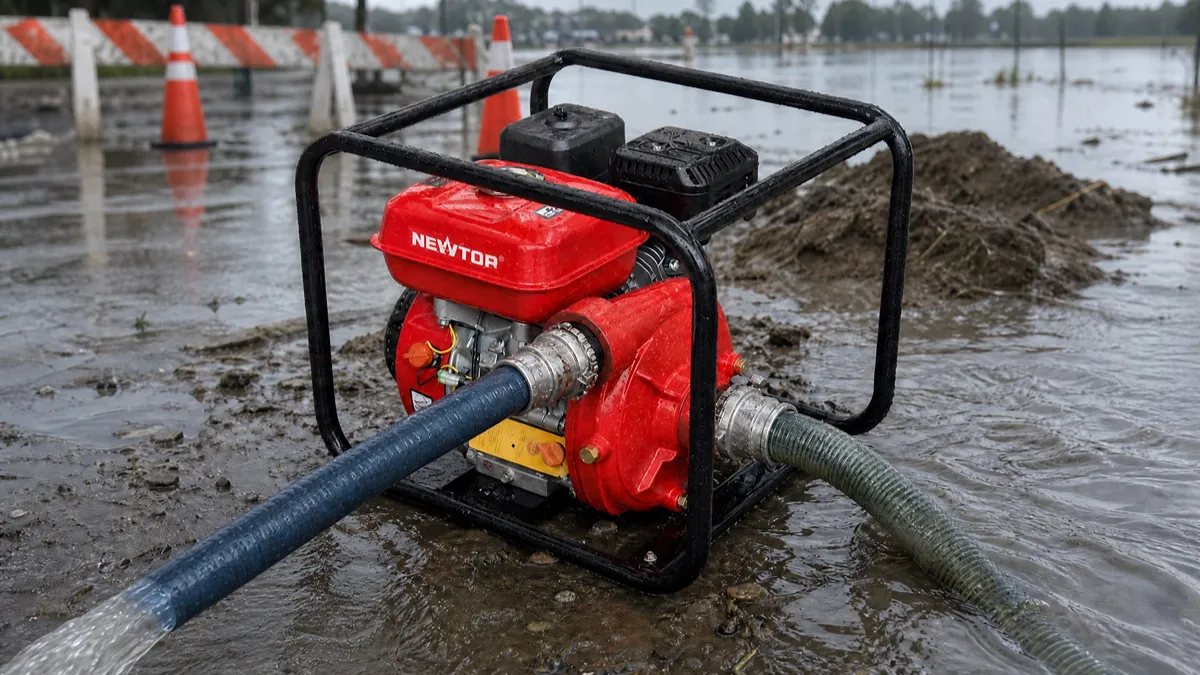
Choosing between a centrifugal pump and a self-priming 펌프 depends on your application, working environment, and customer needs. Centrifugal pumps provide higher efficiency and simple operation for stable water sources, while self-priming pumps offer easier startup and better flexibility for changing conditions.
대리점용, 딜러, 및 OEM 구매자, selecting the right pump type is not only about technical performance but also about market demand, user experience, 장기적인 신뢰성. A pump that works well in a fixed irrigation system may not be the best choice for construction sites or portable water transfer applications.
이 가이드에서는, we will compare centrifugal and self-priming 물 펌프 in terms of working principles, 능률, installation, 유지, applications, and market suitability to help you make a better product selection decision.
What Is a Centrifugal Pump?
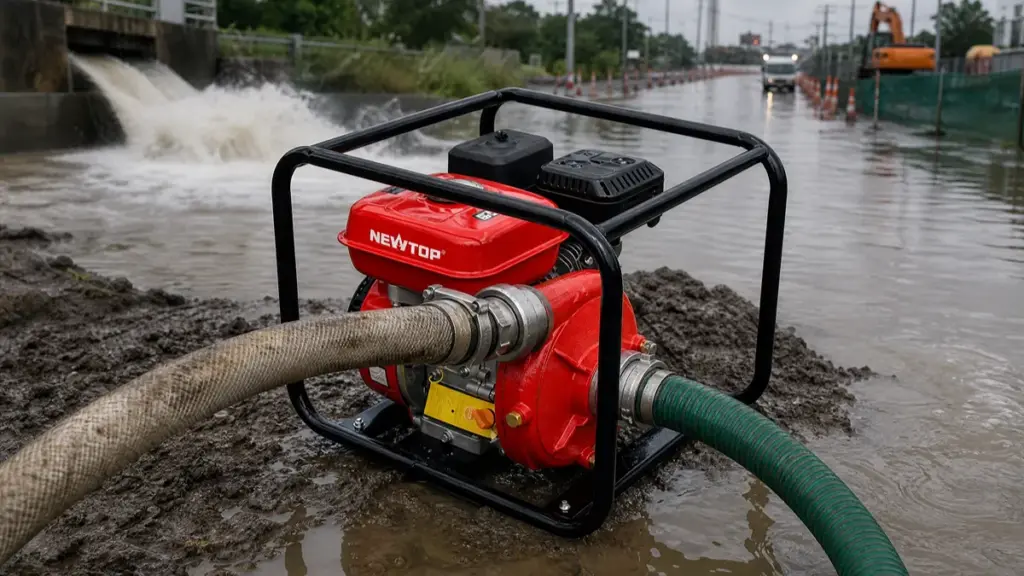
A centrifugal pump is the industry baseline for moving large volumes of water, converting mechanical motor power into hydraulic pressure using a rotating impeller and volute casing.
Core Definition and Energy Conversion
A centrifugal pump is one of the most common types of water pumps used for clean water transfer and irrigation applications. It uses centrifugal force generated by a rotating impeller to move water from the inlet to the outlet.
The mechanism works by increasing the velocity of an incompressible liquid, typically water. As the fast-moving fluid hits the casing walls, the system translates that raw kinetic velocity into usable pressure. Engineers treat this design as the baseline technology for moving large volumes of water against moderate pressure gradients because it delivers continuous flow without excessive mechanical complexity.
What Is a Self-Priming Pump?
A self-priming pump is a specialized centrifugal unit equipped with an internal reservoir to automatically evacuate air and restore liquid flow without repeated manual repriming.
A self-priming pump functions as a specialized centrifugal water machine engineered to evacuate air from its own casing and the connected suction line. Standard centrifugal pumps fail when air enters the system, forcing operators to manually re-prime them. The self-priming design addresses this primary limitation directly.
It incorporates an internal liquid reservoir that generates a vacuum on startup. This mechanism automatically draws water upward into the system before standard pumping begins. Because of this capability, engineers frequently specify these pumps for applications where the equipment must be installed above the water source.
Source High-Margin Garden Machinery Built to Last

How Does a Centrifugal Water Pump Work?
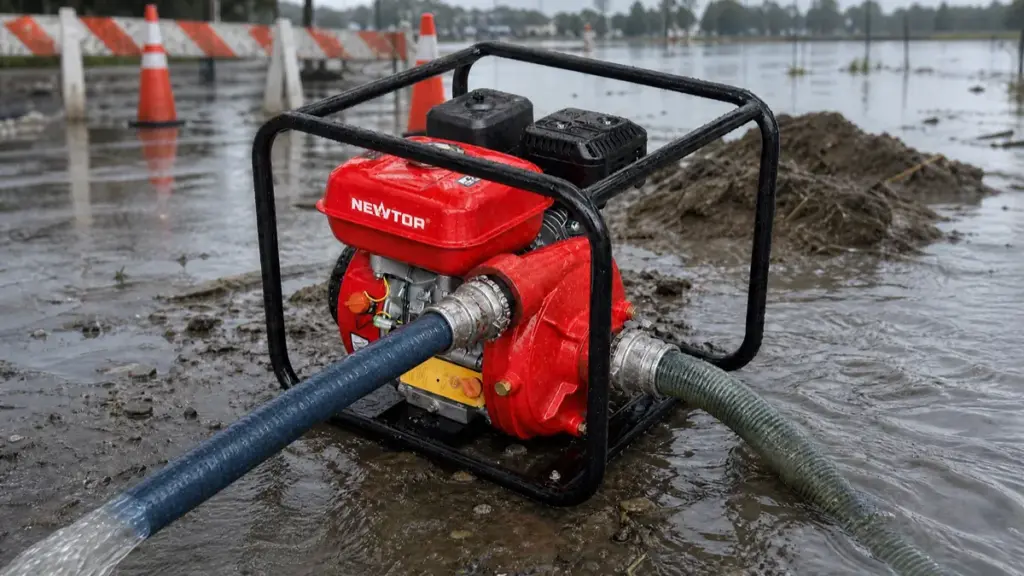
Centrifugal pumps rely on a spinning impeller to convert mechanical rotation into hydrodynamic pressure. They excel at high-volume water transfer but strictly require a fully primed casing before starting.
Core Energy Conversion Principle
At its foundation, a centrifugal pump relies on a straightforward energy exchange. An electric motor or diesel engine supplies rotational kinetic energy to the pump shaft. As the attached impeller spins, it transfers that mechanical energy directly to the incoming water, rapidly accelerating its velocity.
Once the water leaves the impeller blades at high speed, it slams into the surrounding casing. The casing acts as a conversion zone, forcing the high-velocity fluid to decelerate and transforming that kinetic energy into static pressure. This resulting pressure, or head, gives the water the force it needs to push through a piping network.
Key Internal Components
To understand the fluid dynamics, you need to look at the hardware doing the heavy lifting. Three primary components dictate pump performance:
- 임펠러: A shaft-driven wheel equipped with curved blades. It uses centrifugal force to push water radially outward from the center.
- 포장 (Volute or Diffuser): This stationary housing encloses the impeller. It features an expanding flow area designed to smoothly decelerate the water and build system pressure.
- Shaft and Motor: These elements supply the mechanical torque required for rotation. In standard water applications, the motor typically drives the shaft at speeds between 1750 그리고 3500 rpm.
Step-by-Step Fluid Flow Process
The actual movement of fluid happens in a continuous, rapid sequence. Water first enters the pump axially through the suction port, flowing straight into the center—known as the eye—of the impeller. The spinning blades immediately capture this fluid and accelerate it radially outward toward the impeller’s outer edge.
This violent outward movement creates a critical low-pressure zone right at the impeller eye. Atmospheric and static pressure in the suction line react by continuously drawing more water into the pump to fill that void. 그 동안에, the original water hits the expanding wall of the volute casing, decelerates, and exits the discharge nozzle as a highly pressurized stream.
The Role of Initial Priming
Standard centrifugal water pumps share a strict operational constraint: they cannot pump air. Before you initiate startup, the casing and the entire suction line must hold a solid column of water. If air accumulates inside the casing, the impeller simply churns the gas. The unit becomes gas-bound and fails to generate the pressure differential required to move the fluid.
Because standard models lack built-in air evacuation features, they depend heavily on system design. Engineers typically install these units in flooded suction layouts, placing the pump below the water source so gravity maintains the prime. In situations where the pump sits above the water level, operators rely on external vacuum systems or foot valves to keep the system fully primed for the next cycle.
How Does a Self-Priming Water Pump Work?
Self-priming pumps mix retained water with incoming air, expel the air, and create a vacuum to draw liquid from below without manual repriming.
Initial Casing Fill and Seal Formation
Before you hit the power switch for the first time, you must manually fill the built-in reservoir with water. This crucial step prevents dry running, a condition that quickly overheats and destroys the mechanical seal. The retained water creates a hydrodynamic seal between the rotating impeller and the wear plate, establishing the physical conditions necessary for the initial suction action.
Air-Water Mixing at the Impeller
As the impeller starts spinning, it pulls in air from the non-flooded suction line. It aggressively mixes this incoming air with the water already sitting inside the casing directly at the impeller eye. This action forms a dense, pumpable air-water mixture, bypassing the typical air binding failure that stops standard centrifugal pumps.
Separation of Air and Recirculation of Water
The spinning impeller uses centrifugal force to fling the newly formed air-water mixture outward into the outer casing chamber. Inside this larger space, gravity and density take over. The lighter air rises to the top and escapes through an open discharge or a dedicated air-release device. The heavier water drops down and cycles back to the impeller through internal recirculation ports to repeat the mixing process.
Vacuum Creation and Suction Lift
Every time the pump expels a pocket of air, the total volume of air in the suction line drops. This continuous extraction creates a partial vacuum at the impeller eye and throughout the suction piping. With the pressure inside the pipe lowered, the higher atmospheric pressure resting on the below-grade water source pushes liquid straight up the pipe toward the pump inlet.
Transition to Standard Centrifugal Pumping
The priming cycle ends the moment the pump evacuates all the air and floods the entire flow path with water. From this point forward, the unit operates exactly like a conventional centrifugal pump, continuously converting water velocity into pressure for the system discharge. When you eventually shut the pump down, the integrated reservoir holds onto a specific volume of water, keeping the equipment ready for its next automatic prime.
원심 대 자체 프라이밍 워터 펌프: Key Differences at a Glance
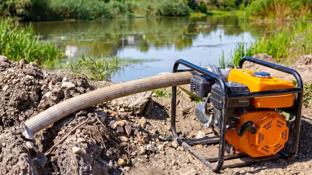
When evaluating a centrifugal vs self-priming water pump, the decision dictates your facility’s energy footprint and maintenance schedule. Engineers must balance peak hydraulic efficiency against the practical realities of air management and suction lift.
| Comparison | Centrifugal Pump | Self-Priming Pump |
|---|---|---|
| Priming requirement | Requires manual priming before operation | Automatically removes air after initial filling |
| Startup speed | Requires additional preparation before starting | Starts faster with less preparation |
| 능률 | Slightly higher efficiency under ideal operating conditions | Slightly lower efficiency due to additional self-priming design features |
| Installation | Best suited for fixed installations with stable water sources | Better for portable and frequently relocated applications |
| Operation conditions | Requires a stable water supply and properly sealed suction line | Handles changing water sources and field conditions better |
| 유지 | Simpler structure with easier maintenance | More components but still easy to inspect and service |
| 비용 | Usually more affordable | Usually higher cost due to additional design features |
| Common users | Farms, factories, 관개 시스템, and fixed water transfer applications | Construction sites, 농업, 비상 배수, and portable water transfer |
Related: 쓰레기 펌프와 깨끗한 물 펌프의 차이점
Priming Mechanism and Air-Handling
Standard centrifugal units rely on a fully flooded suction line to operate. If air enters the system, the impeller loses its hydrodynamic grip, causing the pump to drop its prime. Operators must manually refill the casing from an external source to restore flow, which adds downtime to intermittent operations.
Self-priming pumps take a fundamentally different approach. Once you complete an initial casing fill, they automatically evacuate air from the suction line. They actively process air-water mixtures, expelling the gas and recirculating the liquid until they pull a full vacuum. This structural advantage allows them to re-prime repeatedly without manual intervention.
Internal Design and Complexity
A standard centrifugal pump keeps mechanical complexity to a minimum. The fluid follows a simple, direct hydraulic path straight into the impeller and out through the volute. This streamlined geometry requires minimal mechanical upkeep and keeps initial equipment costs low.
Self-priming designs integrate additional components directly into the pump casing. They feature built-in liquid reservoirs and specialized recirculation chambers engineered to separate air from water. While these internal additions remove the need for external vacuum systems, they require slightly more maintenance. Technicians must routinely inspect these chambers to ensure internal clearances remain tight enough to generate a strong vacuum.
Hydraulic Efficiency and Energy Use
Standard centrifugal pumps dominate in raw energy performance. In continuous, flooded suction applications, they deliver 5 에게 15 percent higher hydraulic efficiency than self-priming variants. The fluid moves efficiently without the drag of secondary separation chambers, keeping power consumption low during 24/7 run cycles.
Self-priming models suffer a minor efficiency penalty by design. Forcing water through internal recirculation paths creates friction and turbulence, demanding slightly more motor power to move the same volume of liquid. But raw efficiency does not always tell the whole story. If a standard pump requires an external vacuum pump or costly foot valves to maintain its prime, deploying a self-priming unit reduces total operational costs by eliminating those auxiliary parts.
Installation Suitability and Application Fit
Facility layout and fluid behavior dictate the final pump selection. Standard centrifugal pumps belong in closed piping networks, municipal water boosting stations, and large industrial cooling loops where flooded suction conditions remain stable.
Self-priming models excel in demanding physical layouts where the equipment sits above the water source. They are the strict requirement for systems facing the following conditions:
- Suction lift applications: Pulling water vertically from underground tanks, deep wells, or sumps.
- Intermittent operations: Managing frequent start-stop cycles where the suction line routinely drains.
- Unstable fluid streams: Handling wastewater or agricultural runoff with high gas entrainment.
Matching the pump to the exact physical demands of the piping network prevents premature wear and ensures continuous fluid delivery.
Which Pump Offers Better Efficiency and Performance?
Standard centrifugal pumps deliver 5-15% higher hydraulic efficiency in flooded systems, while self-priming models offer unmatched operational uptime in suction-lift environments.
Hydraulic Efficiency and Energy Consumption
Standard centrifugal pumps rely on simple hydraulic designs without internal recirculation chambers. This streamlined flow path directly translates to a 5-15% efficiency advantage over self-priming models. Self-priming units integrate built-in reservoirs and air-separation paths to manage suction automatically. These extra internal components create unavoidable friction and hydraulic losses during normal operation. For continuous duty tasks running under steady conditions, standard centrifugal pumps minimize energy consumption and achieve the highest pure wire-to-water efficiency.
Priming Capabilities and Air Handling
Standard centrifugal units demand a guaranteed flooded suction line or dedicated external priming systems to function. If a small air pocket enters the suction piping, the pump quickly loses flow and drops prime. Self-priming pumps solve this operational bottleneck directly. After an initial fill, they automatically separate entrained air from the water, pull a vacuum, and restore prime without manual intervention. When a system involves significant suction lift or draws in gas-laden water, the self-priming design provides superior real-world performance and prevents unexpected shutdowns.
Impact of Duty Cycle and Operating Conditions
The daily operating cycle dictates which pump architecture actually performs better in the field. Selecting the right design requires matching the pump to the exact physical demands of the site.
- Continuous operations: Stable tasks like municipal boosting stations and closed HVAC loops heavily favor the pure hydraulic efficiency of standard centrifugal models.
- Intermittent tasks: Dewatering, sump emptying, and variable-flow duties benefit from the rapid auto-repriming capabilities of self-priming pumps.
- Harsh environments: Pumping dirty water or slurries requires the rugged reliability of a self-priming unit to sustain flow despite solid debris and air ingestion.
Cost Implications and Long-Term Value
Financial performance ties directly to the installation environment. Standard centrifugal pumps carry a lower initial purchase price, occupy a smaller footprint, and require straightforward mechanical maintenance. Self-priming models demand a higher upfront capital investment due to their complex casing designs.
This extra cost pays off by eliminating the need for expensive external vacuum systems, priming tanks, and foot valves. Choosing the right pump comes down to a strict metric comparison: you either prioritize minimizing kWh consumption under ideal, continuous conditions, or you maximize system uptime and reduce labor costs in challenging, air-prone environments.
Which Pump Is Easier to Install and Maintain?
Standard centrifugal pumps offer mechanical simplicity, while self-priming models reduce system-level complexity by eliminating external priming hardware in lift applications.
Installation Requirements and Physical Footprint
Standard centrifugal pumps feature a compact, lightweight casing. This lean design makes physical installation straightforward when dealing with tight structural spaces. You can mount them quickly without massive baseplates or heavy lifting equipment.
That physical simplicity comes with strict system-level demands. Standard models require a flooded suction setup or external priming hardware. You must design suction piping carefully to prevent air traps that could cause the pump to air-bind.
Self-priming centrifugal pumps take the opposite approach. They have larger, heavier casings due to their built-in fluid reservoirs and internal air-separation chambers. Getting them onto the pad requires more effort and physical space.
Despite their bulk, self-priming units simplify system-level installation for lift applications. By integrating the priming mechanism directly into the casing, they eliminate the need to install external vacuum systems or prone-to-fail foot valves.
Routine Mechanical and Operational Maintenance
From a pure wrench-turning perspective, standard centrifugal pumps are mechanically simpler to disassemble and inspect. They involve fewer internal components and cavities, making routine teardowns and seal replacements fast and predictable.
Operational maintenance tells a different story. If air enters a standard 펌프 시스템, the workload increases significantly. Technicians face manual repriming and must spend time troubleshooting auxiliary priming devices to restore flow.
Self-priming pumps manage air autonomously. They automatically evacuate air and re-prime themselves after an initial fill. This capability reduces manual operator interventions and prevents unplanned downtime when suction conditions fluctuate.
While self-priming models remove the burden of external priming hardware maintenance, they introduce a different service point. Their internal recirculation passages may require occasional cleaning to clear sludge and debris in dirty-water applications.
What Applications Are Best for Each Pump Type?
Standard centrifugal pumps dominate continuous, flooded-suction applications, while self-priming models excel in suction-lift, intermittent, and air-prone setups. Match the pump’s air-handling ability to your system’s reality.
Different working environments require different pump characteristics.
Centrifugal Pump Applications
Centrifugal pumps are suitable for:
- Agricultural irrigation systems
- Water circulation
- Industrial water transfer
- Residential water supply
- Fixed pumping stations
They are ideal when users need stable operation and high efficiency.
Self-Priming Pump Applications
Self-priming pumps are commonly used for:
- Construction site drainage
- Flood water removal
- Farm irrigation from rivers or ponds
- Portable water transfer
- Emergency pumping
They are preferred when flexibility and quick operation are more important than maximum efficiency.
How to Choose the Right Water Pump for Your Market
Matching pump types to local suction limits, duty cycles, and maintenance skills prevents costly field failures and protects your dealer margins.
For OEM buyers and distributors, product selection should consider customer needs, local conditions, and market expectations.
Key factors include:
1. Water Source Conditions
If customers use a fixed water tank or permanent pipeline system, centrifugal pumps are often enough.
If water sources come from rivers, 우물, or temporary locations, self-priming pumps provide better reliability.
2. Customer Skill Level
Markets with professional operators may accept centrifugal pumps.
For general users, farmers, and rental customers, self-priming pumps offer easier operation.
3. Transportation and Mobility
Portable gasoline water pumps are often moved frequently. 이러한 경우, self-priming models provide better convenience.
4. Target Price Segment
Centrifugal pumps usually offer a more economical solution, while self-priming pumps provide additional value through easier operation.
A strong product portfolio often includes both options to cover different customer segments.
Why OEM Buyers Choose Both Pump Types from NEWTOP
Sourcing both centrifugal and self-priming pumps from NEWTOP allows OEMs to build tiered product lines, standardize supply chains, and lower engineering overhead.
As an experienced outdoor power equipment manufacturer, 뉴탑 understands that different markets require different pumping solutions.
By offering both centrifugal and self-priming gasoline water pumps, NEWTOP helps distributors build a complete product range for agriculture, 건설, 관개, and emergency water applications.
NEWTOP water pumps are designed with:
- 믿을 수 있는 gasoline engines for stable operation
- Durable pump bodies for demanding working environments
- User-friendly designs for easier operation
- Strict 품질 관리 during production
- OEM customization support for different markets
With manufacturing experience in outdoor power equipment, NEWTOP supports global partners with dependable products, flexible solutions, and long-term cooperation.
Whether your market needs efficient centrifugal pumps or versatile self-priming pumps, NEWTOP can help you select the right configuration for your customers.
최종 생각
Choosing between a standard centrifugal and a self-priming water pump comes down to balancing peak hydraulic efficiency against field reliability. While sourcing a single, cheaper pump type might seem cost-effective initially, matching the correct internal architecture to your buyers’ exact suction conditions protects your margins from preventable dry-run failures. Maintaining a diversified inventory of both standards allows you to secure contracts across every sector, from stable municipal distribution to unpredictable agricultural dewatering.
Building a resilient OEM pump catalog requires verifiable performance data and consistent manufacturing quality. We recommend testing our hydraulic designs firsthand to ensure they align perfectly with your regional market demands. Contact our engineering team to review technical specifications, discuss custom production runs, and arrange sample units for your own field validation.
자주 묻는 질문
What is the difference between a standard centrifugal pump and a self-priming pump?
Standard centrifugal pumps require a flooded suction line and manual priming. Self-priming models include a built-in liquid reservoir that automatically evacuates air from the suction line, allowing the pump to draw fluid and run without external priming assistance.
Do self-priming pumps need manual priming?
You must manually fill the casing before the very first use. After this initial setup, they retain enough fluid in their internal chamber to automatically re-prime during future starts. This works as long as the casing does not completely drain or leak between cycles.
Which pump is better for agricultural use?
Standard centrifugal models work best for continuous, large-scale irrigation from stable surface water sources like ponds. If the setup requires lifting water from wells, uses mobile equipment, or experiences fluctuating water levels, a self-priming pump provides much better reliability.
Are self-priming pumps less efficient than standard centrifugal pumps?
Generally, centrifugal pumps have slightly higher efficiency because of their simpler design. 하지만, self-priming pumps can provide better overall productivity by reducing setup time and operational problems.
Can standard centrifugal pumps handle intermittent operation?
They tolerate intermittent motor start/stop cycles perfectly fine. But they fail if the liquid supply itself is intermittent. If air enters the suction line or the water source drops, the pump loses prime and stops moving fluid until an operator manually refills the system.
Which pump is easier to maintain in the field?
Standard centrifugal pumps feature simpler internal designs with fewer specialized parts, making them easier to rebuild and troubleshoot on-site. Self-priming units contain complex internal recirculation passages and reservoirs that demand specific clearances and more experienced technicians to service correctly.
What pump is better for dealer resale in developing markets?
Self-priming centrifugal pumps generally move faster in these markets. They offer higher reliability for buyers dealing with variable water sources, frequent power interruptions, and suction lift needs, significantly reducing setup friction for users with limited technical maintenance skills.
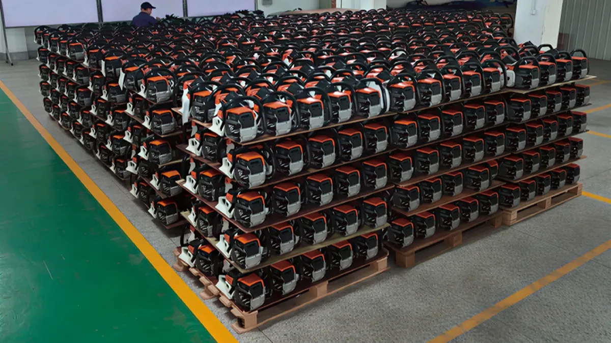
금속 주조 및 정밀 가공부터 엔진 조립까지 전기톱 제조의 모든 단계, 가이드바 생산, 및 최종 테스트 - 일관된 품질과 안정적인 작동을 보장하는 데 중요한 역할을 합니다..
이 가이드에서는 최신 전기톱이 어떻게 제조되는지 단계별로 설명합니다., 각 생산 단계에 관련된 기술, 전문 전기톱 제조업체와 일반 공급업체를 구별하는 품질 표준.
전기 톱의 주요 구성 요소는 무엇입니까?
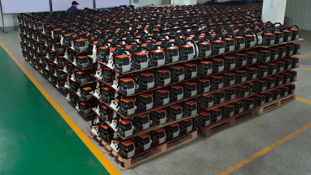
제작 과정을 살펴보기 전에, 전기톱을 구성하는 주요 구성 요소를 이해하는 것이 도움이 됩니다..
교체 부품 또는 OEM 부품을 찾고 있는 경우, 우리의 전체 제품군을 살펴보세요 전기톱 부품 및 액세서리, 가이드 바 포함, 톱 체인, 기화기, 클러치 어셈블리, 점화 시스템, 및 기타 필수 예비 부품.
| 요소 | 기능 |
|---|---|
| 엔진 또는 모터 | 절단력 제공 |
| 실린더 & 케이스 | 연소 시스템을 수용합니다. |
| 크랭크 샤프트 & 피스톤 | 연소를 회전력으로 변환 |
| 기화기 | 연료와 공기를 효율적으로 혼합합니다. |
| 가이드 바 | 톱 체인을 지지하고 안내합니다. |
| 체인톱 | 실제 절단을 수행합니다. |
| 클러치 시스템 | 엔진 동력을 체인으로 전달 |
| 체인 브레이크 | 안전을 위해 체인을 빠르게 정지시킵니다. |
| 연료 & 석유탱크 | 연료 및 체인 윤활유 저장 |
| 플라스틱 하우징 | 무게를 줄이면서 내부 구성 요소를 보호합니다. |
| 핸들 & 진동 방지 시스템 | 편안함과 운전자 안전 향상 |
단계 1: 고강도 엔진 부품용 금속 주조
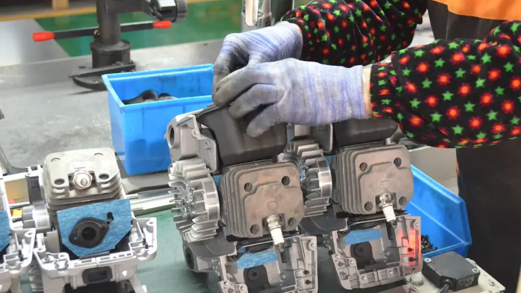
모든 전기톱은 강력한 기초, 즉 엔진에서 시작됩니다.. 가공이나 조립을 시작하기 전, 제조업체는 금속 주조를 통해 엔진의 구조 구성 요소를 만듭니다..
가장 중요한 주조 부품에는 크랭크케이스가 포함됩니다., 실린더, 플라이휠, 클러치 드럼, 및 기타 하중 지지 구성 요소. 이러한 부품은 지속적인 진동을 견뎌야 합니다., 고온, 편안한 작동을 위해 충분히 가벼운 동시에 빠른 엔진 속도. 뉴탑 핸들로의 진동 전달을 최소화하는 통합 진동 방지 시스템으로 사용자 편의성을 더욱 향상시킵니다., 장시간 작업에도 더욱 안전하고 편안한 작업 가능. 믿을 수 있는 전기톱 제조사를 찾고 계시다면, NEWTOP의 모든 전문 분야를 살펴보세요 가솔린 전기톱 OEM 및 글로벌 유통을 위해 설계됨.
부품의 기능에 따라 다양한 주조 공정이 선택됩니다.:
| 주조 공정 | 일반적인 구성요소 | 주요 장점 |
|---|---|---|
| 고압 다이캐스팅 | 알루미늄 크랭크케이스, 엔진 하우징 | 뛰어난 치수 정확도, 높은 생산 효율성 |
| 중력 다이캐스팅 | 실린더 헤드, 중간 볼륨 구성 요소 | 더 나은 기계적 강도와 표면 품질 |
| 모래 주조 | 대형 또는 저용량 구성요소 | 툴링 비용 절감 및 설계 유연성 향상 |
| 투자 주조 | 스틸 클러치 부품, 톱니 | 높은 정밀도와 우수한 표면조도 |
알루미늄 합금은 뛰어난 강도 균형을 제공하기 때문에 대부분의 엔진 하우징에 선호되는 소재입니다., 내식성, 열 방출, 그리고 체중 감소. 강철 또는 연성철은 일반적으로 더 높은 내마모성이 요구되는 고부하 변속기 및 클러치 부품에 사용됩니다..
캐스팅 후, 모든 부분이 트리밍을 거칩니다., 샷 블라스팅, 가공부로 이동하기 전 사전 치수검사 및 사전 치수검사. 플래시 제거, 버, 이 단계의 표면 결함은 나중에 생산 과정에서 일관된 가공 정확도를 보장하는 데 도움이 됩니다..
단계 2: 중요 부품의 정밀 CNC 가공
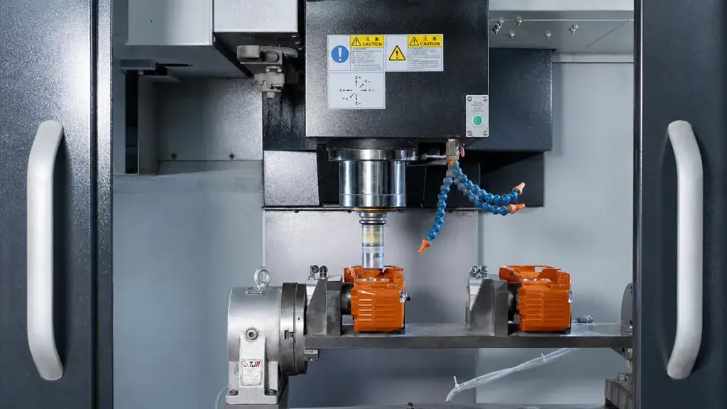
주조는 각 부품의 기본 형상을 만들어냅니다., 그러나 현대 전기톱 엔진 내부에 요구되는 엄격한 공차를 달성할 수는 없습니다.. 정밀 CNC 가공은 엔진 성능과 신뢰성을 결정하는 최종 치수를 생성합니다..
컴퓨터로 제어되는 머시닝 센터는 다양한 작업을 수행합니다., 포함:
- 실린더 보링
- 크랭크샤프트 저널 가공
- 베어링 시트 마감
- 나사 태핑
- 표면 밀링
- 기어 가공
- 드릴링 오일 통로
많은 전기톱 제조 업체 다축 CNC 머시닝 센터를 사용하여 단일 설정으로 여러 작업을 완료, 생산 시간을 단축하면서 일관성을 향상.
실린더 보어는 가장 중요한 가공 작업 중 하나입니다.. 직경, 진원도, 표면 마감은 피스톤 씰링에 직접적인 영향을 미칩니다., 압축, 연료 효율, 그리고 엔진 수명. 사소한 치수 오류라도 마찰을 증가시키거나 엔진 성능을 저하시킬 수 있습니다..
가공 후, 좌표 측정기 (CMM), 레이저 측정 장비, 정밀 게이지는 부품 조립을 진행하기 전에 모든 중요 치수가 사양 내에 있는지 확인합니다..
단계 3: 경량 하우징용 플라스틱 사출 성형
엔진이 동력을 공급하는 동안, 많은 외부 전기톱 부품은 전체 무게를 줄이고 사용자 편의성을 향상시키기 위해 플라스틱 사출 성형을 사용하여 제조됩니다..
일반적인 사출 성형 부품에는 다음이 포함됩니다.:
- 전면 및 후면 핸들
- 스타터 커버
- 공기 필터 커버
- 연료탱크
- 오일 탱크
- 체인 브레이크 하우징
- 측면 커버
- 보호 가드
PA6 등 엔지니어링 플라스틱, PA66, ABS, 폴리프로필렌 (PP), 유리섬유 강화 나일론은 내충격성이 뛰어나 일반적으로 사용됩니다., 우수한 치수 안정성, 그리고 연료에 대한 저항, 기름, 그리고 자외선 노출.
사출 성형 공정은 여러 단계로 구성됩니다.:
- 플라스틱 펠릿은 녹을 때까지 가열됩니다..
- 재료는 고압에서 정밀 금형에 주입됩니다..
- 냉각 채널은 플라스틱을 빠르게 응고시킵니다..
- 부품이 금형에서 자동으로 배출됩니다..
- 검사 전 게이트와 플래시를 제거합니다..
현대 생산 라인에서는 자동 부품 제거 및 트리밍을 위해 로봇 시스템을 사용하는 경우가 많습니다., 일관된 품질을 유지하면서 생산 효율성을 향상시킵니다..
성형된 각 부품에 싱크 마크가 있는지 검사합니다., 뒤틀림, 플래시, 최종 조립 라인에 들어가기 전 치수 정확도.
단계 4: 엔진 조립 및 전력 시스템 통합
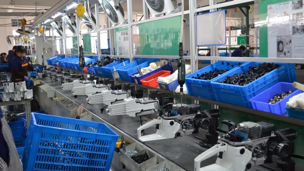
모든 엔진 부품이 제조되면, 기술자들은 세심하게 통제된 절차에 따라 완전한 동력 장치를 조립합니다..
일반적인 조립 순서에는 다음이 포함됩니다.:
- 크랭크샤프트 베어링 설치
- 크랭크샤프트 압입
- 피스톤 및 피스톤 링 설치
- 커넥팅로드 연결
- 실린더 장착
- 씰 및 개스킷 설치
- 점화 시스템 조립
- 기화기 설치
- 클러치와 플라이휠 장착
엔진 조립 후, 점화시기, 기화기 설정, 동력 장치가 최종 제품 조립으로 진행되기 전에 압축 및 압축을 확인합니다..
현대 생산 라인에서는 바코드 또는 QR 코드 추적을 사용하여 조립 데이터를 기록합니다., 제조 내역 전반에 걸쳐 모든 엔진을 추적할 수 있습니다..
프리미엄 정원 기계로 마진을 극대화하세요
단계 5: 가이드바 및 쏘체인 제작
가이드 바와 톱 체인은 전기톱의 절단 시스템을 구성하며 엔진 생산과는 별도의 전문 제조 공정이 필요합니다..
가이드바 제조
가이드 바는 일반적으로 고강도 합금강으로 생산됩니다.:
- 스틸 블랭킹
- 열처리
- 홈 가공
- 노즈 스프로킷 설치 (스프로킷 노즈 바용)
- 연마
- 표면 코팅
- 최종검사
열처리는 경도를 높이는 동시에 중절삭 시 굽힘 및 균열에 견딜 수 있는 충분한 인성을 유지합니다..
체인톱 제조
톱 체인은 보이는 것보다 훨씬 더 복잡합니다.. 단일 체인에는 정밀하게 제조된 수백 개의 부품이 포함되어 있습니다., 포함:
- 커터 이빨
- 드라이브 링크
- 타이 스트랩
- 리벳
각 커터 톱니에는 스탬프가 찍혀 있습니다., 열처리, 정밀지면, 일관된 절단 성능을 제공하기 위해 날카롭게 연마되었습니다..
자동화된 리벳팅 기계는 정확한 체인 피치와 관절을 유지하면서 개별 링크를 완전한 체인으로 조립합니다.. 조립 후, 체인에 윤활유가 바르다, 장력 테스트를 거침, 원활한 작동을 위해 점검을 하였으며.
고품질 체인에는 내마모성을 향상시키고 서비스 수명을 연장하기 위해 크롬 도금 커터 톱니와 경화 리벳이 특징인 경우가 많습니다..
단계 6: 최종 조립, 성능 테스트, 및 품질검사
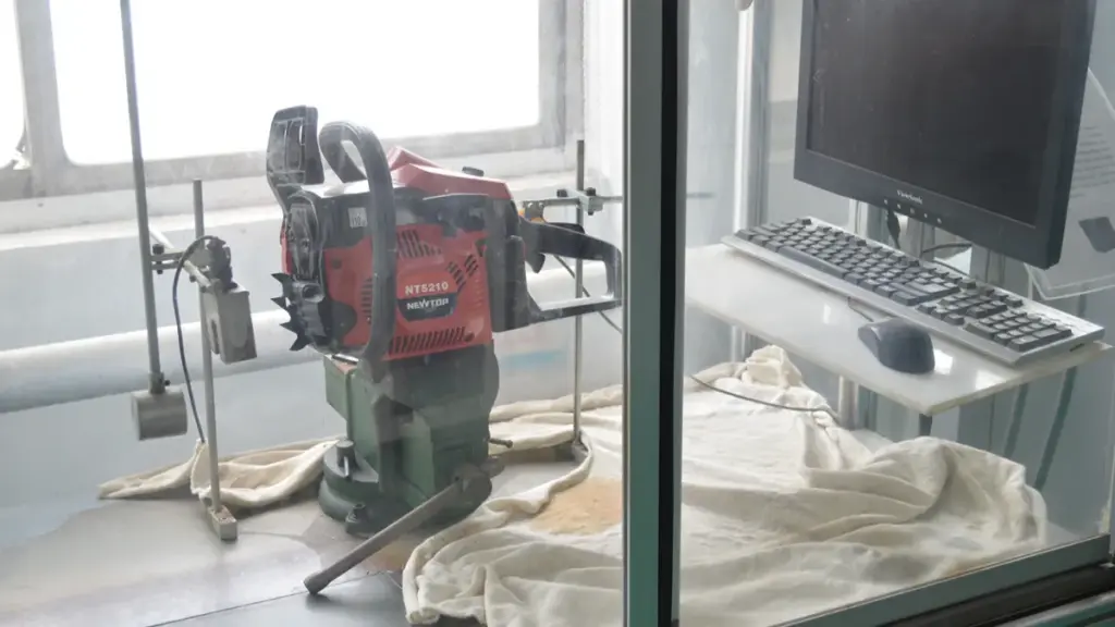
마지막 단계에서는 모든 구성 요소를 배송 준비가 완료된 전기톱으로 통합합니다..
최종 조립 중, 작업자가 완성된 엔진을 설치하다, 가이드 바, 톱 체인, 플라스틱 하우징, 연료 시스템, 점화 부품, 핸들, 안전 장치, 및 제어 메커니즘.
각 전기톱은 포장하기 전에 여러 가지 품질 검사를 거칩니다..
일반적인 생산 테스트에는 다음이 포함됩니다.:
| 검사항목 | 목적 |
|---|---|
| 토크 검증 | 패스너가 조립 사양을 충족하는지 확인하세요. |
| 압축 테스트 | 엔진 씰링 성능 검증 |
| 점화 테스트 | 안정적인 스파크 발생 확인 |
| 연료 시스템 누출 테스트 | 연료 누출 방지 |
| 체인 브레이크 테스트 | 작업자 안전 확인 |
| 유휴 속도 테스트 | 안정적인 엔진 작동 보장 |
| 최대 RPM 테스트 | 엔진 성능 확인 |
| 소음 및 진동 테스트 | 작동 편의성 평가 |
| 육안검사 | 외관 품질 및 조립 정확도 확인 |
뉴탑에서, 모든 전기톱 모델은 최대 100km의 엄격한 내구성 테스트를 거칩니다. 200 시간 까다로운 작동 조건에서. 고품질 부품과 엄격한 제조 표준으로 제작, NEWTOP 전기톱은 다음을 제공하도록 설계되었습니다. 이상 500 시간 전문적인 사용 하에서의 직장 생활, 임업에 안정적인 성능 제공, 조경, 및 상업용 애플리케이션.
모든 검사 절차를 통과한 후에만 전기톱이 청소됩니다., 액세서리와 설명서가 함께 포장되어 있습니다., 그리고 배송 준비 완료.
전기톱 공장이 충족해야 하는 인증 및 표준은 무엇입니까??
인증은 신뢰할 수 있는 전기톱 제조업체가 국제적으로 인정받는 품질을 따르고 있음을 입증합니다., 안전, 및 환경 요구 사항.
목표 시장에 따라, 신뢰할 수 있는 전기톱 공장은 다음과 같은 표준을 준수해야 합니다.:
| 인증 | 목적 |
|---|---|
| ISO 9001 | 품질경영시스템 |
| CE | 유럽 안전 요구 사항 준수 |
| GS | 독일 제품 안전 인증 |
| EPA | 우리를. 배출 규정 준수 |
| 탄수화물 | 캘리포니아 배기가스 기준 |
| RoHS 규제 | 유해물질 제한 |
| 도달하다 | 화학 안전 준수 |
뉴탑에서, 품질과 규정 준수는 제조의 모든 단계에 통합됩니다.. 우리 공장은 다음과 같이 운영됩니다. ISO 9001 인증 품질 경영 시스템, 당사의 제품은 국제 표준 및 인증을 준수합니다., 포함 CE, GS, EPA, RoHS 규제, 도달하다, 제품 모델 및 대상 시장에 따라. 이를 통해 유럽 전역의 OEM 고객을 지원할 수 있습니다., 북아메리카, 그리고 다른 많은 글로벌 시장에서도 자신있게.
품질 관리를 통해 안정적인 전기톱 성능을 보장하는 방법

일관된 전기톱 성능은 엄격한 기준에 달려 있습니다. 품질 관리, 정확한 부품 공차부터 엄격한 안전 검증 및 배송 전 독립적인 실험실 테스트까지.
| QC 단계 | 핵심 중점 분야 | 주요 목표 |
|---|---|---|
| 명세서 | 차원 & 자재 제한 | 생산 기준 수립. |
| 들어오는 QC | 보어 크기 & 그루브 폭 | 불량 부품 조기 차단. |
| 진행 중 | 실수 방지 & PFMEA | 조립 오류 방지. |
| 최종 테스트 | 절단 속도 & 안전 | 기능적 성능 검증. |
기술 사양 및 공급업체 표준 수립
품질 관리는 부품이 조립 라인에 도착하기 훨씬 전부터 시작됩니다.. 제조업체는 허용되는 구성 요소를 구성하는 요소에 대한 정확한 경계를 설정하기 위해 자세한 기술 문서에 의존합니다.. 이 기반은 공급망이 어떻게 운영되는지를 규정하고 모호한 표준이 최종 제품의 품질을 저하시키는 것을 방지합니다..
- 차원 정의: 엔지니어링 팀은 실린더의 정확한 치수 공차를 설정합니다., 가이드 바, 정렬을 보장하고 진동을 방지하는 체인.
- 재료 선택: 생산 관리자는 혹독한 산림 환경에서 살아남을 수 있도록 내마모성 강철 합금 및 내충격성 플라스틱에 대한 엄격한 요구 사항을 설정합니다..
- 공급업체 감사: 조달팀은 전용 전동 공구 생산 라인에 대한 파트너 공장을 감사합니다., 고급 CNC 가공, 전문적인 열처리 능력.
들어오는 품질 관리 (IQ) 중요 부품용
완성된 전기톱을 분해하는 것보다 소스에서 결함을 찾아내는 것이 훨씬 저렴하고 안전합니다.. 들어오는 품질 관리 (IQ) 파워헤드나 절단 시스템이 손상되기 전에 표준 이하의 원자재와 구매 부품을 걸러냅니다..
- 절단 부착 검사: 검사관 테스트 가이드 바 홈 폭, 레일 평행도, 기술 도면에 대한 체인 피치 공차.
- 엔진 부품 검증: 기술자가 실린더 보어 크기를 확인합니다., 진원도, 좌표 측정기를 사용한 피스톤 치수.
- 하드웨어 검증: 직원 확인 패스너, 잠금 장치 트리거, 하중이 가해졌을 때 안전 장치가 작동하도록 보장하는 체인 브레이크 스프링.
공정 중 관리 및 제조 안정성
대량 생산 라인에는 교대조에 따른 변동이 발생할 수 있는 변수가 발생합니다.. 공정 내 제어로 제조 안정성 유지, 개별 워크스테이션을 격리하여 조립 오류가 발생하는 순간 감지.
- 프로세스 매핑: 엔지니어는 PFMEA를 사용하여 제조 단계를 매핑하여 클러치 설치 및 기화기 튜닝과 같은 고위험 작업에 대한 제어 우선순위를 정합니다..
- 조립 보조물: 작업자는 잘못된 구성 요소 정렬을 방지하기 위해 실수 방지 지그와 go/no-go 고정 장치를 활용합니다..
- 미드라인 점검: QC 직원은 엔진 시동 동작 및 예비 가이드 바 추적에 대한 중간 기능 테스트를 수행합니다..
최종 성능 테스트 및 안전 검증
기계적 조립이 완료되면, 테스트는 정적 차원에서 동적 성능으로 전환됩니다.. 모든 장치 또는 샘플링된 배치는 시뮬레이션된 현장 조건에서 효율적으로 절단하고 안전하게 종료할 수 있음을 입증해야 합니다..
- 절단능력: 기술자는 표준화된 목재 샘플에 대한 테스트 절단을 수행하여 절단 속도를 확인합니다., 부드러움, 칩 배출.
- 안전 시스템: 검사관이 체인 브레이크 반응 시간을 검증합니다., 스로틀 잠금, 킬 스위치 신뢰성.
- 시각적, 신체적 적합성: QA 팀은 올바른 체인 장력 범위에 대해 최종 조립을 확인합니다., 안전한 가드 정렬, 전반적인 미용 무결성.
독립적인 검증 및 문서화 표준
국제 구매자는 내부 공장 보고서에 대한 독립적인 검증을 신뢰합니다.. 제3자 테스트와 엄격한 문서화를 통해 글로벌 공급망을 정직하게 유지하고 수입 시 브랜드의 명성을 보호합니다..
- 제3자 감사: 브랜드는 AQL 선적 전 샘플링 및 규정 준수 실험실 테스트를 위해 독립적인 검사 회사를 고용합니다..
- 물리적 기준선: 생산팀은 승인된 황금 샘플을 최종 적합 기준으로 사용합니다., 마치다, 성능.
- 엄격한 기록 보관: 공장에서는 모호성을 제거하고 범위 변동을 방지하기 위해 상세한 이중 언어 사양 팩과 주문 확인을 유지합니다..
OEM 전기톱 제조업체로 NEWTOP을 선택해야 하는 이유?
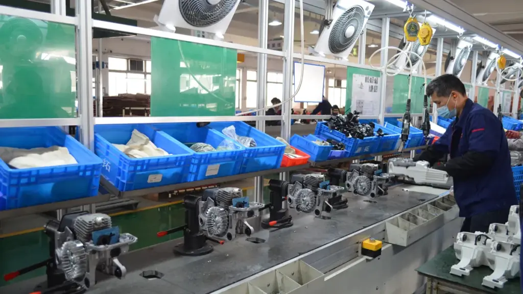
NEWTOP과의 파트너십을 통해 유통업체는 완전한 인증을 받을 수 있는 직접적인 파이프라인을 제공합니다., 즉각적인 글로벌 시장 진입을 위해 제작된 확장 가능한 전력 장비.
올바른 제조 파트너를 선택하려면 가격을 비교하는 것 이상이 필요합니다.. 유능한 공장은 엔지니어링 전문 지식을 결합해야 합니다, 안정적인 생산 능력, 엄격한 품질 관리, 반응이 빠른 고객 지원.
~에 뉴탑, 부품 생산부터 최종 조립까지 전체 제조 공정을 통합하여 모든 주문에서 일관된 제품 품질을 보장합니다..
우리의 제조 장점은 다음과 같습니다:
- 이상 20 옥외 전력 장비 분야에서 다년간의 제조 경험
- 고급 CNC 가공 및 자동 조립을 갖춘 현대적인 생산 시설
- 모든 생산 단계에서 엄격한 품질 관리
- 선적 전 종합 테스트
- OEM 및 ODM 맞춤화 지원
- 유통업체와 브랜드 소유자를 위한 유연한 생산 능력
- 다양한 국제 시장에 걸친 글로벌 수출 경험
새로운 전기톱 브랜드를 출시하든 기존 제품 라인을 확장하든, NEWTOP은 신뢰할 수 있는 제조 지원을 제공할 수 있습니다., 안정적인 품질, 귀하의 비즈니스 성장을 위한 장기적인 파트너십.
자주 묻는 질문
중국 공장에서 OEM 전기톱 주문을 처리할 수 있나요??
중국 공장은 엔드투엔드 OEM 전기톱 생산을 쉽게 처리합니다.. 설계 적용 및 전력 매개변수 조정부터 맞춤형 브랜딩 및 수출 포장까지 완벽한 지원을 기대할 수 있습니다.. 휘발유 전용선을 운영하는 시설, 유선 전기, 배터리로 구동되는 리튬 이온 모델.
대량 전기톱 생산에는 일반적으로 시간이 얼마나 걸립니까??
대량 생산주기는 프로젝트 범위에 따라 다릅니다.. 표준 반복 배치가 완료됩니다. 5 에게 15 부품이 조립 라인에 도착한 후 며칠. 프로토타입 검증 및 맞춤형 금형 제작이 필요한 새로운 OEM 실행 3 에게 6 주. 일단 메인 컨베이어에, 단일 장치에 대한 물리적 조립 및 테스트는 단 몇 시간만 소요됩니다. 10 에게 30 분.
제조업체는 배송 전에 전기톱을 어떻게 테스트합니까??
품질 관리 팀은 포장 전 전용 테스트 워크샵을 통해 전기톱을 작동합니다.. 압력을 가하여 엔진 씰을 테스트합니다., 유휴 및 고속 RPM 임계값 보정, 물리적인 나무 자르기 실험을 수행합니다.. 검사관은 중요한 안전 구성 요소도 테스트합니다., 체인 브레이크 반응 시간 포함, 스로틀 잠금, 그리고 엔진 킬 스위치.
전기톱의 내구성을 보장하기 위해 어떤 재료가 사용됩니까??
전문 전기톱 생산에서는 가이드 바 및 톱 체인용 고탄소 합금강을 사용합니다.. 프리미엄 절삭날은 마모를 줄이기 위해 이중 크롬 도금 또는 브레이징 카바이드 인서트를 특징으로 하는 경우가 많습니다.. 파워헤드의 경우, 제조업체는 경량 알루미늄 또는 마그네슘 합금으로 엔진 블록을 주조하고 충격 방지 엔지니어링 플라스틱으로 외부 하우징을 성형합니다..
전기톱 제조업체에서 어떤 인증을 찾아야 합니까??
ISO 하에 운영되는 공장을 찾아보세요 9001 품질경영과 ISO 14001 환경 기준. 제품 자체의 경우, 목표 시장에 따라 정확한 요구 사항이 결정됩니다.. 유럽 수입품은 기계 및 EMC 지침을 포괄하는 CE 마크를 요구합니다., 소음 및 진동 준수와 함께. TÜV Rheinland와 같은 인정받은 연구소의 검증된 테스트 보고서는 신뢰성에 대한 가장 강력한 증거를 제공합니다..
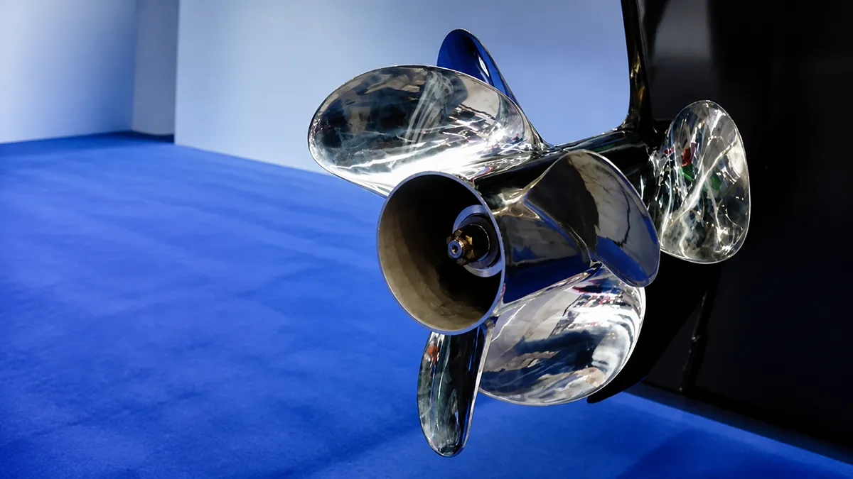
Choosing the right outboard propeller is not simply about finding a model that fits the engine shaft. A propeller directly affects acceleration, 최고 속도, 연료 소비, 엔진 부하, and overall boating experience.
For boat builders, 유통업체, and marine equipment buyers, selecting the wrong propeller can lead to poor performance, excessive vibration, higher fuel costs, and even long-term engine issues.
A reliable propeller selection process should consider several factors, including engine specifications, boat characteristics, 작동 조건, blade design, material choice, and supplier capability.
This guide explains the key points buyers should check before purchasing an outboard propeller and how to make a more accurate selection for different applications.
What Key Information Should You Prepare Before Choosing a Propeller?
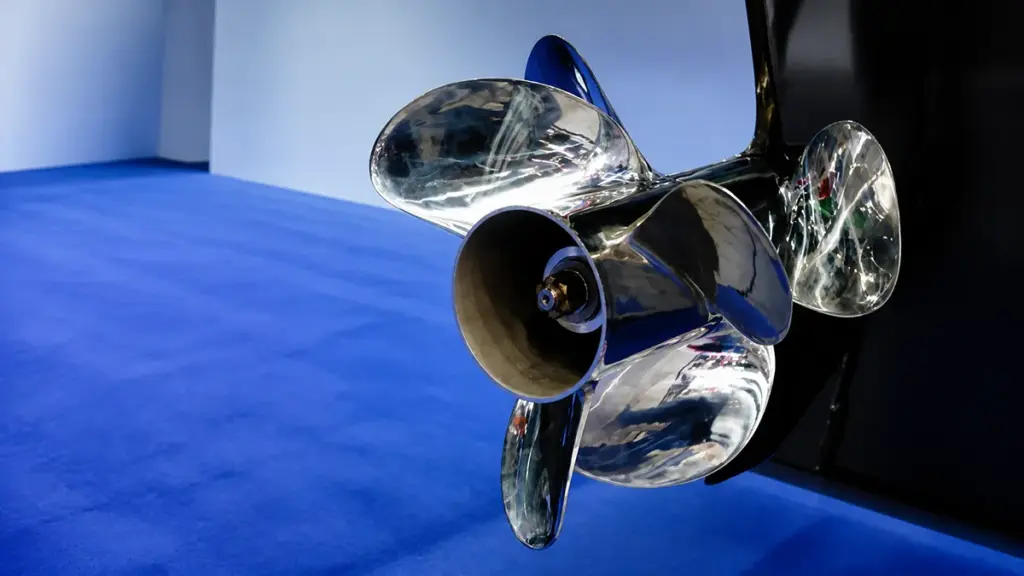
Before comparing propeller models, collect accurate information about the engine, 보트, and daily use. This reduces fitting errors and gives the supplier enough data to recommend a suitable starting configuration.
Prepare the following details:
| Data Category | Metrics to Record |
|---|---|
| Current Propeller | 지름, 정점, rotation, 블레이드 수, 재료, hub splines |
| Engine Details | Rated HP, gearcase size, target WOT RPM, actual WOT RPM |
| Boat Profile | 길이 (LOA), hull shape, operating weight, speed goals |
| Usage Environment | Primary activity, cruise speed, water conditions (fresh/salt/shallow) |
| Benchmarks | GPS speed at WOT, time to plane, ventilation in turns |
Current Propeller Specifications
Your existing propeller serves as the baseline for any future adjustments. You need exact numbers off the current hub or blades to know which direction to adjust your pitch or diameter.
- Diameter and pitch: Record these numbers (usually stamped on the barrel, 좋다 14 엑스 19) to establish your starting point.
- 회전 방향: Identify if the prop uses right-hand or left-hand rotation. This matters heavily for twin-engine setups.
- Blades and material: Note if you run a 3-blade or 4-blade design, and whether it is cast aluminum or stainless steel.
- Hub and shaft details: Count the splines on the prop shaft and measure the shaft diameter to ensure your replacement physically fits the gearcase.
Engine Details and WOT RPM Limits
Engine specifications define your operating envelope. Your motor has a specific RPM band where it makes peak power safely, and your prop must keep the engine inside that band.
- HP and gearcase size: Verify your rated horsepower and gearcase dimensions. These dictate which propeller families fit the outboard.
- Target WOT RPM: Find the manufacturer’s recommended Wide Open Throttle (WOT) RPM 범위. Modern outboards usually target 5,000 에게 6,000 RPM.
- Actual WOT RPM: Measure your current wide-open RPM under a normal load. This tells you if the engine is over-revving or lugging.
- Trim systems: Note if the boat has power trim or trim tabs. These systems dictate how you tune the hull attitude to reach optimal RPM.
Boat Characteristics and Load Profile
Hull design and operating weight directly influence thrust requirements. A heavy pontoon pushes water differently than a light bass boat, demanding a totally different blade geometry.
- Hull dimensions: Document the length overall (LOA), hull material, and bottom shape (like deep-V or flat-bottom). These dictate drag and required lift.
- Operating weight: Calculate your realistic load. Include fuel, 승객, 기어, and livewells.
- Load frequency: Identify if you frequently run heavily loaded. Heavy loads often require stepping down in pitch or moving to a 4-blade prop to maintain thrust.
- Speed targets: Define your present top speed against your desired top speed. This guides the tradeoff between pitch and acceleration.
Usage Profile and Operating Environment
How and where you drive determines the optimal propeller style. You must align the design with your primary on-water activities to get the best efficiency.
- Primary use: Specify if you focus on high-speed cruising, heavy towing for watersports, or commercial work.
- Running speeds: Identify your typical throttle positions. This determines if you optimize for mid-range fuel economy or absolute top-end speed.
- 물 상태: Consider your environment. Abrasive, 남자 이름, or shallow waters often demand the durability of stainless steel over standard aluminum.
Real-World Performance Benchmarks
Never buy a new propeller without testing the old one first. You need hard performance data to compare against your post-installation results.
- Baseline test runs: Take the boat out and record maximum RPM and GPS speed at wide-open throttle, trimming up just before the prop cavitates.
- Acceleration metrics: Evaluate your hole shot, the time it takes to get on plane, and the boat’s ability to hold a plane at lower speeds.
- Handling checks: Monitor the steering for signs of propeller ventilation, excessive slip during hard turns, or cavitation in rough chop.
How Do Diameter and Pitch Affect Propeller Performance?
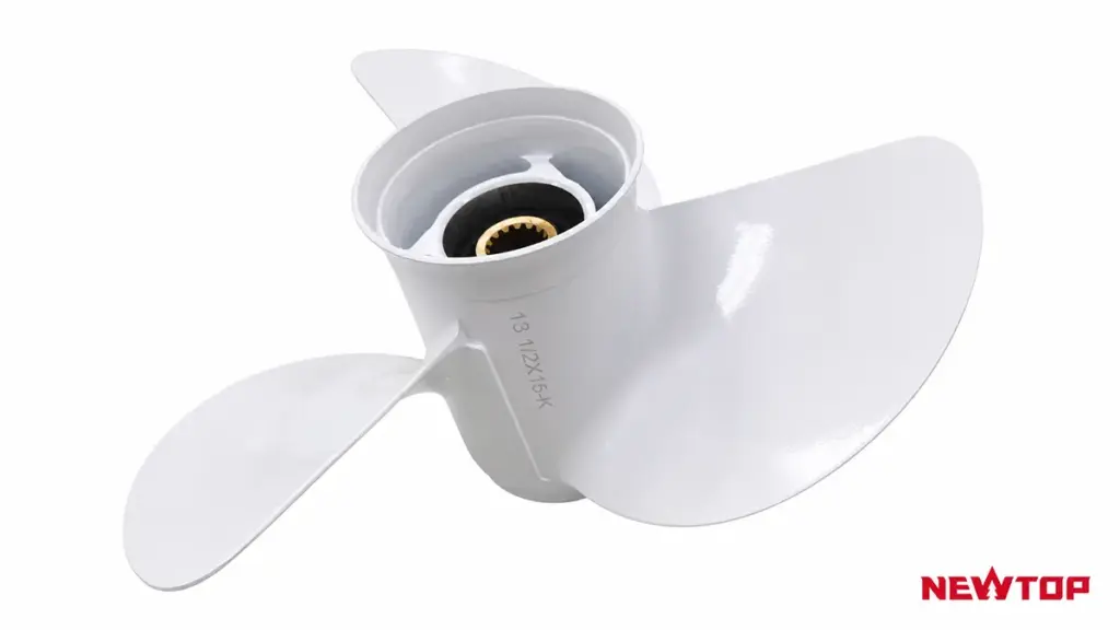
Diameter and pitch are two of the most important measurements in propeller selection. They determine how efficiently an outboard propeller converts engine power into thrust and directly influence acceleration, 최고 속도, 연료 효율, and engine RPM.
Before choosing a replacement propeller, buyers should understand what these two specifications mean and how they work together. A propeller marked as 14 × 19, 예를 들어, indicates a 14-inch diameter and a 19-inch pitch. The first number represents diameter, while the second number represents pitch.
For a more detailed explanation of propeller markings and how these measurements affect performance, buyers can refer to our guide on what pitch and diameter mean on an outboard propeller.
지름 refers to the distance across the full circle made by the rotating blades. A larger diameter generally produces more thrust because it moves more water with each rotation.
Large-diameter propellers are commonly used for:
- Heavy boats
- Commercial applications
- Boats that require strong pulling power
- Low-speed operation
A smaller diameter propeller usually allows higher RPM and may support better top-speed performance on lightweight boats.
정점 refers to the theoretical distance a propeller moves forward in one complete rotation without considering slip. 예를 들어, a 19-inch pitch propeller is designed to move approximately 19 inches per rotation under ideal conditions.
The relationship between pitch and performance is:
| Pitch Choice | Performance Effect |
|---|---|
| 낮은 피치 | 더 빠른 가속, stronger thrust, easier engine operation |
| 더 높은 피치 | Higher potential speed, lower RPM, suitable for light loads |
하지만, increasing pitch does not always increase speed. 피치가 너무 높은 경우, the engine may struggle to reach its recommended RPM range, causing poor acceleration and increased stress.
A proper selection balances pitch, 지름, 엔진 출력, and boat load. Many buyers use factory recommendations as a starting point and then adjust based on real operating conditions.
Source Durable Garden Machinery at Competitive Prices
How Does the Number of Blades Influence Speed, 추력, and Fuel Efficiency?
Blade count dictates the balance between top speed and load capacity. Fewer blades reduce drag for maximum speed, while more blades provide necessary grip for heavy loads.
The Relationship Between Blade Area and Drag
Every propeller blade moving through water creates surface friction and pressure drag. Fewer blades result in a smaller total wetted area, directly translating to lower hydrodynamic drag and higher potential open-water efficiency.
Adding blades increases the Blade Area Ratio (BAR). A higher BAR gives the propeller significantly more grip on the water, reducing slip and ventilation. The trade-off is higher hydrodynamic interference between the blades, demanding more power to turn at the exact same RPM.
How Blade Count Affects Top Speed
Two-blade propellers theoretically offer the highest top speeds on lightly loaded hulls because they encounter minimal drag. For most recreational planing hulls, three-blade designs hit the sweet spot. A well-matched three-blade propeller consistently runs 5% 에게 10% faster at wide-open throttle compared to a four-blade setup.
Upgrading to a four-blade propeller usually cuts peak speed by about 2 에게 3 시속. Yet, these high-blade configurations maintain effective speed much better in rough water or high-trim conditions by actively resisting blowout.
Thrust Capabilities and Load Management
Total thrust depends heavily on the total blade area. A propeller with fewer blades forces each blade to carry a higher unit thrust. Push a low-blade-count prop too hard under a heavy load, and you risk severe cavitation or structural stress at the blade root.
Four-blade and high-BAR three-blade propellers excel at managing demanding workloads. You need these configurations for:
- Heavy Boats: Lifting heavy hulls onto plane quickly.
- Towing Applications: Delivering strong mid-range acceleration.
- Limited Clearances: Maximizing thrust when gearcase size limits the maximum diameter.
Fuel Efficiency and Optimal Engine Loading
For standard recreational setups, a correctly sized three-blade propeller delivers the best steady-cruise fuel economy. The minimal drag allows the outboard to run efficiently near its peak torque band.
Adding a fourth blade increases the physical load on the engine. You almost always need to drop the pitch to keep the wide-open throttle RPM within the manufacturer’s optimal range. On heavily loaded boats, a four-blade propeller can actually improve real-world fuel efficiency. By drastically reducing slip, it holds the boat on plane at lower RPMs, burning less fuel than a three-blade prop struggling to grip the water.
Should You Choose an Aluminum or Stainless Steel Propeller?
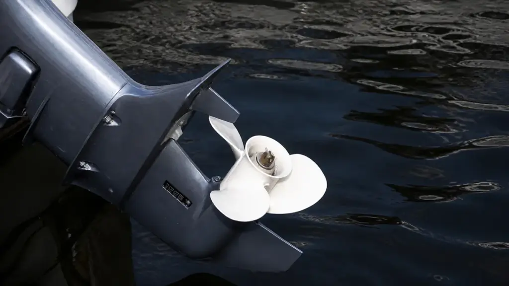
Aluminum offers budget-friendly protection for shallow waters and lower horsepower, while stainless steel delivers speed, grip, and durability for high-performance outboards and saltwater environments.
For buyers who want to understand the detailed differences between these two materials, including strength, 내구성, 유지, and application scenarios, our guide on aluminum vs stainless steel outboard motor propellers provides a complete comparison.
Matching Material to Outboard Horsepower
Outboard horsepower directly dictates the ideal propeller material. For motors under 30 HP, manufacturers almost exclusively equip factory aluminum propellers. Stainless steel options in this range remain scarce and offer little practical performance benefit.
Mid-range engines between 30 그리고 70 hp pair perfectly with aluminum for general recreational boating. The power output at this level rarely causes severe blade flex, keeping performance stable for everyday use. Once you step up to outboards producing 75 hp and above, the operating dynamics change. These engines generate high torque and push heavier loads, making stainless steel the standard choice to handle the increased thrust without losing blade shape.
Durability and Lower Unit Risk
How a propeller reacts to underwater impacts determines the safety of your lower unit gears. You must evaluate your primary operating environment before making a choice.
- Sacrificial protection: Aluminum acts as a sacrificial component, bending or cracking upon impact to absorb shock and protect lower unit gears.
- Impact transfer: Stainless steel withstands normal wear and minor impacts, but transfers heavy strike forces directly to the prop shaft.
- Shallow hazards: Boaters navigating shallow, stump-filled, or rocky rivers should select aluminum to minimize expensive gearcase repairs.
- Saltwater endurance: Marine environments heavily favor stainless steel due to its superior long-term corrosion resistance.
Hydrodynamic Performance and Handling
Material stiffness heavily influences thrust efficiency. Manufacturers cast aluminum blades thicker to achieve necessary strength, but they still flex under heavy loads. This flexing slightly reduces top-end speed and high-RPM stability. Stiff, thin stainless steel blades maintain their precise pitch and shape under pressure, improving thrust efficiency and maximizing water displacement.
Upgrading to a stainless steel model often yields a 2 에게 3 mph speed gain alongside stronger acceleration for heavy loads. Stainless steel also holds cupping better than aluminum. This structural advantage ensures reliable grip during tight turns and drastically reduces ventilation issues on the water.
Cost Comparison and Lifespan Value
An aluminum propeller costs roughly one-third the price of a comparable stainless steel model. Budget-conscious buyers and boaters who frequently replace damaged props benefit the most from this low upfront cost. The inexpensive replacement strategy makes sense when striking rocks or stumps is a routine risk.
Stainless steel requires a much higher initial investment. It provides exceptional lifespan in deep, obstruction-free waters where impact damage is rare. The long-term value quickly shifts to stainless steel for performance rigs, as the durable material eliminates the need for frequent replacements and maintains optimal fuel efficiency over thousands of hours of use.
How Do Engine Horsepower and Gear Ratio Affect Propeller Selection?
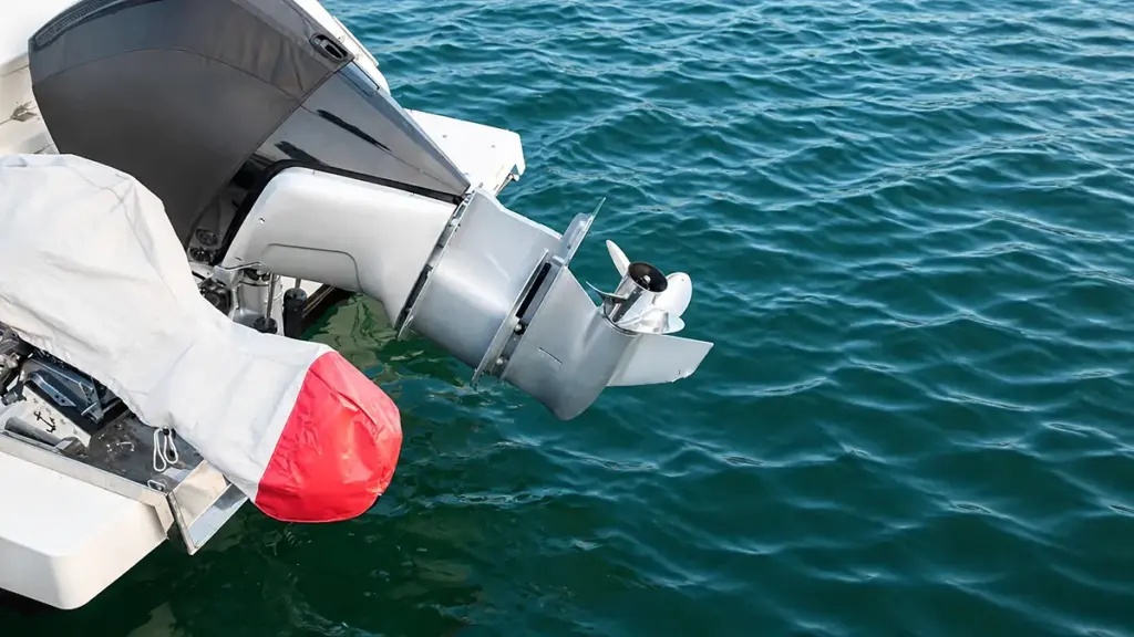
Horsepower dictates the maximum propeller size an engine can efficiently turn, while gear ratio determines shaft speed. 함께, they establish the exact pitch required to hit target WOT RPM.
The Role of Engine Horsepower in Propeller Sizing
Engine horsepower sets the baseline power budget for moving a boat efficiently. A higher horsepower rating allows an outboard to turn a larger diameter or a higher-pitch propeller without struggling. Buyers must match the propeller to the engine’s usable horsepower at the intended operating RPM, rather than looking strictly at peak horsepower marketing numbers.
If you choose an oversized or over-pitched propeller, the engine will lug and fail to reach its intended power band. Undersize the propeller, and the engine will over-rev, leaving valuable performance unused and risking mechanical damage.
How Gear Ratio Determines Propeller Shaft Speed
Gear ratio acts as a primary input that fundamentally changes the final propeller load. It is not just a secondary detail. You calculate propeller shaft RPM directly by dividing the engine RPM by the gear ratio.
A higher numerical gear ratio reduces the prop shaft speed and multiplies torque. To restore the desired boat speed, this setup requires a higher-pitch propeller. 거꾸로, a lower numerical gear ratio spins the propeller faster at a given engine RPM, requiring reduced pitch to prevent the engine from over-revving.
Balancing Pitch and Final RPM for Optimal Performance
Adjusting the gear ratio triggers a chain reaction in pitch selection. Increasing a gear ratio numerically usually requires stepping up the propeller pitch by two to four sizes. Since a single pitch size change typically alters engine speed by 250 에게 350 RPM, pitch adjustments serve as the ideal mechanism for fine-tuning wide-open-throttle (WOT) RPM.
Operating conditions also alter this power dynamic. Heavy boat loads and high elevations demand less pitch to keep the engine from dropping below its optimal power band. For high-RPM outboard designs, manufacturers frequently use reduction ratios of 2.3:1 or higher to properly manage the aggressive propeller shaft speed and hydrodynamic load.
Practical Selection Steps for Outboard Buyers
Start the selection process by identifying the engine’s rated horsepower, gear ratio, and recommended WOT RPM range. 거기에서, execute a systematic testing sequence to dial in the correct specifications:
- Baseline Selection: Select a propeller size that lets the engine reach target RPM under expected load, elevation, and water conditions.
- Pitch Adjustment: Reduce pitch if the engine fails to reach target RPM, or increase pitch if the engine over-revs during initial testing.
- Sea Trial Verification: Conduct a final loaded test run to account for specific real-world variables like hull drag, running weight, and ventilation behavior.
How Does Boat Type Influence the Right Propeller Choice?
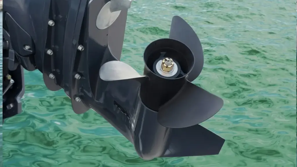
Hull design and typical boat load dictate required thrust and RPM. Matching pitch and diameter to your specific vessel type prevents engine lugging and maximizes hydrodynamic efficiency.
High-Speed Planing and Performance Boats
빛, performance-focused hulls like bass boats or sport rigs require setups that minimize drag once on plane. Your primary goal is converting engine torque directly into top-end speed while keeping the outboard near its maximum RPM limit.
To achieve this, operators utilize higher pitch and moderate-to-smaller diameter profiles. High-speed setups rely heavily on 3-blade stainless steel propellers, which deliver the durability and thin-blade efficiency needed to push past 50 mph without flexing.
Watersports and Tow-Sport Configurations
Pulling wakeboarders, skiers, or heavy tubes demands a massive initial surge of thrust. Absolute top speed takes a backseat to a strong hole shot and smooth mid-range pulling power.
Tow boats require lower pitch and larger diameter profiles to move heavily ballasted setups without dropping below the engine’s power band. Owners frequently utilize 4-blade propellers to improve low-speed handling, reduce slip, and keep the boat securely on plane.
폰툰, Tritoons, and Heavy Cruisers
These vessels push a massive amount of water. High frontal drag and heavy, variable passenger loads mean your propeller must maximize water displacement rather than chase speed.
Pontoons and heavy cruisers benefit from larger diameter and moderate-to-low pitch to generate adequate low-speed thrust. This exact configuration prevents engine lugging and ensures the motor reaches its specified WOT RPM despite the heavy structural drag.
General Fishing and All-Purpose Vessels
Aluminum fishing boats and versatile center consoles operate across diverse conditions. The ideal setup balances rapid acceleration, mid-range cruise efficiency, and precise low-speed maneuverability around docks or structure.
Most operators pair moderate pitch with 3-blade designs to achieve versatile performance during long runs. When conditions dictate, shifting to 4-blade setups provides better grip offshore or improves shallow-water stern lift on flats boats.
Sailboats and Displacement Hulls
Displacement hulls cannot exceed their theoretical hull speed regardless of applied power. Propeller selection must focus entirely on low-speed thrust and reliable maneuvering in tight quarters.
Operators use large-diameter, low-pitch profiles to push displacement hulls efficiently at modest engine speeds. This approach protects auxiliary outboards from overloading when fighting strong currents or heavy headwinds.
What Operating Conditions Should Buyers Consider?
Propeller selection requires analyzing actual boat weight, typical water conditions, engine RPM limits, and horsepower output to prevent drivetrain damage and maximize fuel efficiency.
Boat Load and Usage Patterns
Evaluating typical operating loads is the first step in propeller selection. A boat behaves entirely differently when running solo compared to a hull weighed down by passengers, heavy gear, full fuel tanks, or towing duties.
Always prop the boat so the engine reaches the upper end of its wide-open-throttle (WOT) rpm range when lightly loaded. This rpm buffer prevents the engine from lugging once you introduce heavy weight.
- Variable Usage: Boats shifting between light solo fishing trips and fully loaded family cruising require either a compromise propeller or a dedicated two-prop setup.
- Heavy-Duty Operations: Towing, rescue, and workboats demand high, continuous thrust. These roles favor larger diameter, lower-pitch propellers designed to run efficiently at lower rpm.
Engine RPM Matching and Performance Goals
The propeller acts as the final gear ratio between the engine and the water. It must keep the outboard operating inside the manufacturer-specified WOT rpm range. Operating outside this band degrades fuel efficiency and accelerates mechanical wear.
Pitch adjustments directly dictate engine speed. Increasing pitch by one inch typically decreases WOT rpm by approximately 200 rpm, while decreasing pitch raises it by the same amount.
- Planing Hulls: These setups require rapid hole shot and target a controlled slip factor of 8-15% at WOT for peak efficiency.
- Displacement Hulls: Slow-speed vessels ignore top-end speed to focus entirely on generating maximum low-end torque.
- Real-World Validation: Empirical WOT testing with proper trim adjustments is the only reliable way to validate rpm matching and fuel burn under actual operating conditions.
Water Environment and Surface Conditions
The physical water environment dictates blade geometry. Rough water causes the hull to pitch, increasing the risk of the propeller breaking the surface. Propellers with increased blade area or aggressive cupping hold water better and reduce ventilation in heavy chop.
Calm water applications allow operators to take the exact opposite approach, prioritizing higher pitch and lower drag designs to push top-end speed.
- Hazardous Environments: Shallow or debris-filled waters guarantee eventual bottom strikes. These areas require durable materials and responsive motor trim capabilities to protect the drivetrain.
- Water Flow Quality: Propellers require clean, undisturbed water to generate optimal thrust. Poor mounting heights or excessive hull turbulence will cause aeration and immediate power loss.
Outboard Horsepower and Structural Demands
Engine output strictly determines the required material strength. High-horsepower outboards, typically rated at 140 hp and above, exert extreme torque that overwhelms weaker metals and causes aluminum blades to flex.
Rigid stainless steel propellers are the primary choice for high-output engines. Stainless maintains its exact designed geometry under heavy loads and high speeds, providing predictable thrust and maximum traction.
- Lower-Horsepower Applications: General-purpose and lower-hp engines perform exceptionally well with aluminum propellers. They offer a cost-effective, impact-forgiving alternative that acts as a sacrificial part during bottom strikes.
- Exhaust Compatibility: You must verify the propeller design integrates correctly with the lower unit’s specific exhaust routing, particularly for through-hub exhaust systems.
What Common Propeller Selection Mistakes Should Buyers Avoid?
Avoiding common propeller selection mistakes—like guessing pitch, ignoring typical loads, or neglecting lower unit fitment—saves fuel, protects the engine, and prevents costly on-water failures.
Misjudging RPM, 정점, and Load Requirements
Buyers often sabotage outboard performance by selecting a propeller without validating how it impacts the engine’s actual operating range.
- Ignoring the WOT RPM range: Failing to match the propeller to the engine’s recommended Wide Open Throttle (WOT) limits causes the engine to lug under heavy load or over-rev at top speed.
- Prioritizing theoretical top speed: Selecting pitch just to hit a high top-speed number ignores the inverse effect pitch has on RPM and low-end acceleration.
- Testing on an empty boat: Finalizing a prop choice with a light hull gives false data. The boat will struggle to plane once fully loaded with passengers, 기어, and fuel.
Treat the manufacturer’s specified WOT RPM as a hard constraint. You must hit this target under normal, real-world operating loads to ensure efficient running and long engine life.
Overlooking Blade Count and Material Trade-Offs
Many buyers mistakenly believe that simply adding blades or buying the cheapest material will fix performance issues. Every design change shifts the performance curve.
- Assuming more blades equal better performance: Buyers often switch from three to four blades hoping for an outright upgrade, not realizing the extra drag typically drops WOT RPM by 50 에게 150 rpm.
- Shopping by material price: Choosing aluminum over stainless steel strictly to save money ignores your actual environment. Soft aluminum deforms under high load, while stainless steel maintains its shape and efficiency at high speeds.
- Ignoring the primary use case: Buying a propeller designed for fast, solo runs fails if you spend 80% of your time towing wakeboarders or carrying a heavy crew.
Match the blade geometry and material to your actual daily environment. A high-performance stainless steel prop shines in open water but transfers severe shock to the gearcase if you strike a submerged stump in shallow rivers.
Using Flawed Testing and Adjustment Methods
Troubleshooting a sluggish boat requires a systematic approach. Guessing at propeller specs without proper baseline data leads to wasted money and unresolved engine strain.
- Changing multiple variables at once: Swapping pitch, 블레이드 수, and material in a single step makes it impossible to isolate which change improved or hurt performance.
- Ignoring GPS boat speed: Focusing strictly on tachometer readings without verifying actual speed hides secondary issues like extreme prop slip.
- Blaming the prop prematurely: Buyers often fault the propeller for sluggish planing when the real culprit is excessive hull drag, the wrong engine mounting height, or poor trim angle.
Establish a clear baseline with your current setup first. Make single, incremental adjustments—usually starting with pitch—and test the results on the water before changing another variable.
Neglecting Fitment, 유지, and Spares
Even the perfectly pitched propeller fails if it does not physically integrate with the outboard gearcase or lacks basic maintenance.
- Guessing hub compatibility: Buying a prop without checking spline counts, hub system types, or matching thrust washers leads to stripped splines and lower unit damage.
- Ignoring physical damage: A slightly bent blade or fishing line wrapped around the prop shaft mimics the symptoms of incorrect pitch.
- Running without a spare: Operating without a backup prop leaves you stranded after a severe strike and eliminates your ability to swap to a lower-pitch prop for unexpectedly heavy loads.
Verify fitment against the engine transom tag before purchasing. Inspect the prop hub assembly periodically to catch early signs of slippage or corrosion.
최종 생각
Buyers should evaluate engine specifications, 보트 유형, 작동 조건, blade design, material choice, and supplier reliability when bulk buying outboard motor propellers.
The right propeller improves acceleration, 연료 효율, 손질, 그리고 엔진 성능, while the wrong choice can reduce efficiency and increase operating costs.
대리점용, boat manufacturers, and marine equipment companies, working with an experienced outboard propeller supplier provides better product consistency and long-term support.
With advanced manufacturing capability, precision-balanced aluminum and stainless steel propellers, and OEM/ODM production experience, NEWTOP helps global partners develop reliable propeller solutions for different marine applications.
자주 묻는 질문
What should I check before buying an outboard propeller?
Verify your boat’s primary use, typical load profile, and desired performance goals. You must confirm engine specifications, including the brand, horsepower, shaft type, and the manufacturer’s recommended wide-open-throttle (WOT) RPM 범위. Collect baseline data from your current prop, such as diameter, 정점, 재료, and observed WOT RPM, to guide your replacement choices.
How do I choose the right propeller pitch?
Selecting pitch relies on matching the propeller to your engine’s recommended WOT RPM range. Test your current setup at full throttle with a normal load. If the RPM falls below the recommended band, decrease the pitch. If the RPM exceeds the limit, increase the pitch. Changing the pitch by one inch generally alters the engine speed by 150 에게 200 RPM.
Is stainless steel better than aluminum for all users?
아니요. Stainless steel provides superior rigidity, higher top speeds, and excellent saltwater corrosion resistance, making it ideal for high-horsepower engines. Aluminum is highly cost-effective and serves as a sacrificial metal. In shallow or hazard-prone waters, an aluminum propeller will bend or break upon impact, which helps protect the expensive gearcase from severe damage.
What is the best propeller for heavy boats?
Heavy vessels require maximum static thrust and control rather than high top speed. The best approach is selecting a larger diameter propeller with a lower pitch to ensure the engine reaches its target RPM under heavy load. A four-blade design is frequently recommended to improve grip, accelerate planing, and provide smoother handling in rough conditions.
How do I confirm hub compatibility?
Read your engine’s transom tag to find the exact make, 모델, 년도, and gearcase code. Match this data against the new propeller’s specifications, ensuring the spline count and shaft diameter align perfectly. You also need to identify whether your outboard uses a fixed splined bore or a modular insert kit, and verify the proper thrust washer sequence.
What documents should a propeller supplier provide?
A standard procurement package should include a Certificate of Conformance (CoC), material certificates, and final inspection or balance reports. For commercial or classed vessels, suppliers must also provide traceability records and relevant approval documents to prove the delivered hardware meets the required engineering standards.
How important is sample testing before a bulk order?
On-water sample testing is critical because catalog specifications cannot predict how a hull and engine combination will react to complex loads. Testing a small batch validates WOT RPM, 손질, 그리고 연료 효율. Skipping this step risks large-scale inventory issues, engine mis-loading, and severe cavitation problems across the fleet.
What if my engine does not reach recommended RPM with the new prop?
Failing to reach the specified WOT RPM range typically means the boat is over-propped, placing excessive mechanical stress on the engine. If the fuel and ignition systems are healthy, correct the issue by switching to a propeller with a lower pitch or a smaller diameter. A one-inch pitch reduction generally increases engine speed by roughly 150 에게 200 RPM.
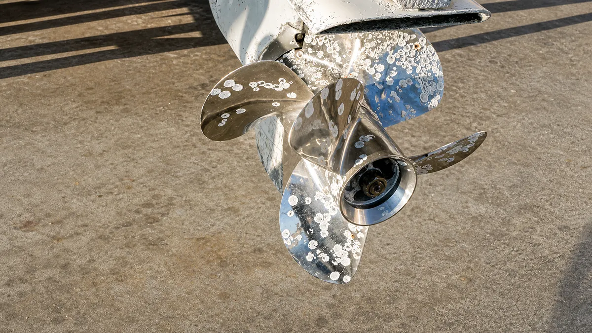
An outboard propeller works in one of the harshest environments on a boat. Every trip exposes it to sand, rocks, floating debris, shallow water, and continuous high-speed rotation. The challenge is that propeller damage often develops slowly. A tiny chip today may become a crack tomorrow, while slight vibration can eventually damage bearings, 물개, or even the lower unit. Learning how to recognize the early warning signs helps boat owners avoid expensive repairs, improve fuel economy, and maintain safe performance on the water.
이 가이드에서는, you’ll learn the most common signs of outboard propeller damage, how to inspect your propeller correctly, when repairs are practical, and when replacement is the better long-term solution.
Why Early Propeller Damage Detection Matters
Direct Performance and Efficiency Impacts
A compromised 추진자 immediately degrades how your vessel moves through the water. Minor blade distortions force the engine to work outside its optimal load range, dragging down overall performance.
- Disrupted hydrodynamics: Damaged blades alter water flow, resulting in lower top speeds and weaker acceleration.
- RPM restrictions: Altered effective 정점 prevents the engine from hitting its designated wide-open throttle RPM.
- Fuel waste: Reduced propeller efficiency forces the outboard to work harder, significantly increasing fuel consumption.
- Vibration and handling: Imbalanced blades induce vibration that impairs steering precision and degrades overall ride comfort.
Preventing Secondary Mechanical Failures
Ignoring a damaged propeller transfers stress directly to your outboard’s internal drivetrain. What starts as a bent blade quickly compromises seals and bearings deep inside the lower unit.
- Contaminated gear oil: Unnoticed cracks near the submerged fin often cause water ingress and gear oil contamination.
- Engine stress: Deformed propellers alter engine load, causing harmful under-revving or over-revving that stresses internal components.
- Accelerated fatigue: Continuous vibration from an imbalanced prop accelerates structural fatigue in gearcase bearings, driveshafts, and engine mounts.
- Overheating risks: Combined with restricted water inlets, poor propeller condition elevates the risk of severe engine overheating.
Vessel Safety and Operational Reliability
Propeller condition dictates your physical control over the vessel. Failing to spot damage early puts both crew and cargo at risk during critical maneuvers.
- Sudden propulsion loss: A progressively failing hub or weakened blade can fracture under load, causing an immediate loss of usable propulsion.
- Collision hazards: Degraded handling and delayed acceleration reduce maneuverability around obstacles, increasing collision risks.
- Schedule integrity: Timely detection minimizes unscheduled downtime, protecting schedule integrity for commercial, charter, and rescue operations.
The Economic Case for Early Intervention
금융 논리는 간단하다. Swapping a damaged propeller costs a fraction of the repair bills required if you leave a compromised unit attached to your motor.
- Low-cost intervention: Propeller inspection and replacement represent a fraction of the cost of total engine or lower unit repairs.
- Halting financial bleed: Catching damage early halts compounding financial losses from excess fuel burn and accelerated part wear.
- Avoiding major rebuilds: Ignoring early indicators frequently leads to expensive gearcase rebuilds, seal replacements, and powerhead repairs.
The First Visible Signs of Outboard Propeller Damage
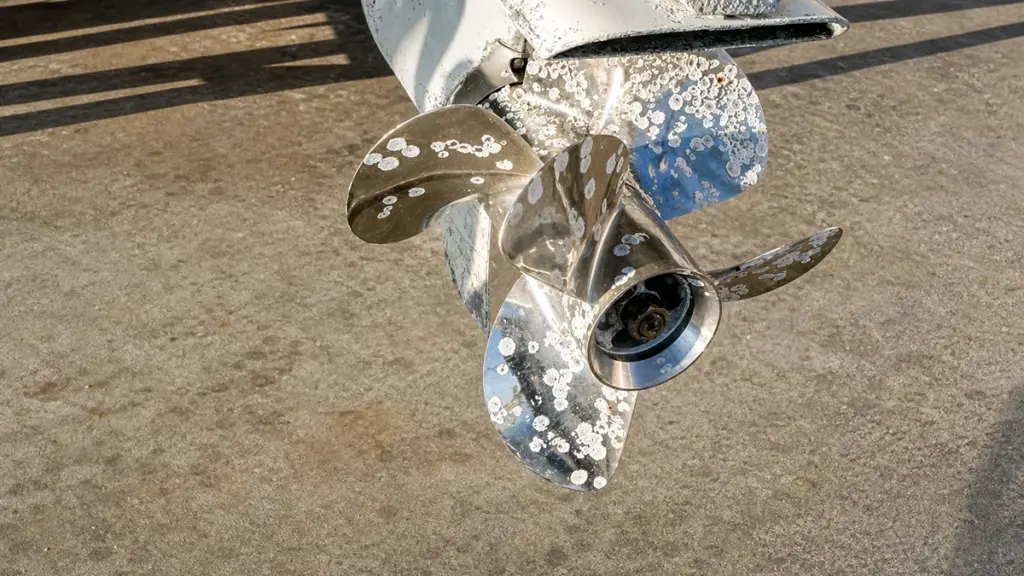
Early detection of outboard propeller damage—like minor nicks, paint wear, or slight bends—prevents escalating fuel costs, vibration-induced drivetrain wear, and sudden propulsion failure.
Paint Deterioration and Superficial Scratches
We often dismiss worn paint as normal wear and tear, but localized paint wear on the blades or hub points to frequent minor impacts with sand or small debris. It acts as the first warning sign before structural bending occurs.
You will typically notice fine scratches appearing on the leading edge first. These surface abrasions usually precede deeper structural wear. Once the protective coating strips away, the exposed bare metal patches create immediate vulnerabilities for accelerated corrosion in saltwater environments.
Nicks, Chips, and Minor Dents
A perfectly smooth edge is essential for hydrodynamic efficiency. Small chips along the leading edge disrupt water flow and increase the risk of cavitation. This turbulent water causes pressure drops that erode the surrounding metal.
Shallow dents on the blade surfaces serve as the earliest structural deformities detectable without specialized tools. Look closely at the trailing edge during inspections. Early material loss at the trailing edge directly impacts the grip and lift of the propeller, which reduces your acceleration and top-end speed.
Subtle Blade Deformation and Bending
Propellers operate under immense load, and even a slight geometric change throws off the balance of the entire drive system. Slightly bent blade tips clearly indicate previous contact with rocks or a hard bottom.
To spot these issues, view the propeller straight from the front. Visible asymmetry suggests uneven deformation from one-sided impacts. Micro warping or twisting alters the pitch and load distribution across the blades. This forces the engine to burn more fuel to maintain your normal cruising speed.
Localized Corrosion and Cavitation Pitting
Material degradation compromises the strength of the unit. Small corrosion pits or powdery white oxidation on aluminum propellers mark areas of material weakening. These spots quickly expand if left unchecked.
Rough, sandblasted patches near high-load regions indicate early cavitation erosion. As vapor bubbles collapse against the metal, they blast away the surface layer. Repeated erosion gradually thins out sections near the leading edge, making them prone to cracking during high-RPM operation.
Visible Hub Misalignment and Scoring
The hub absorbs shift shock and acts as the critical link between the engine and the blades. Scoring or distortion around the hub collar hints at abnormal stress or improper installation. You can test the integrity of the internal rubber bushing with a quick visual diagnostic.
Draw a straight line across the hub and barrel, run the boat under load, and check the marks. Misaligned diagnostic marker lines visually confirm internal hub slippage. You should also check for flattened or peened edges, which reflect a history of running the outboard through shallow, rocky water.
Source High-Margin OEM Garden & 농업 기계
How Vibration, 소음, and Poor Acceleration Reveal Damage
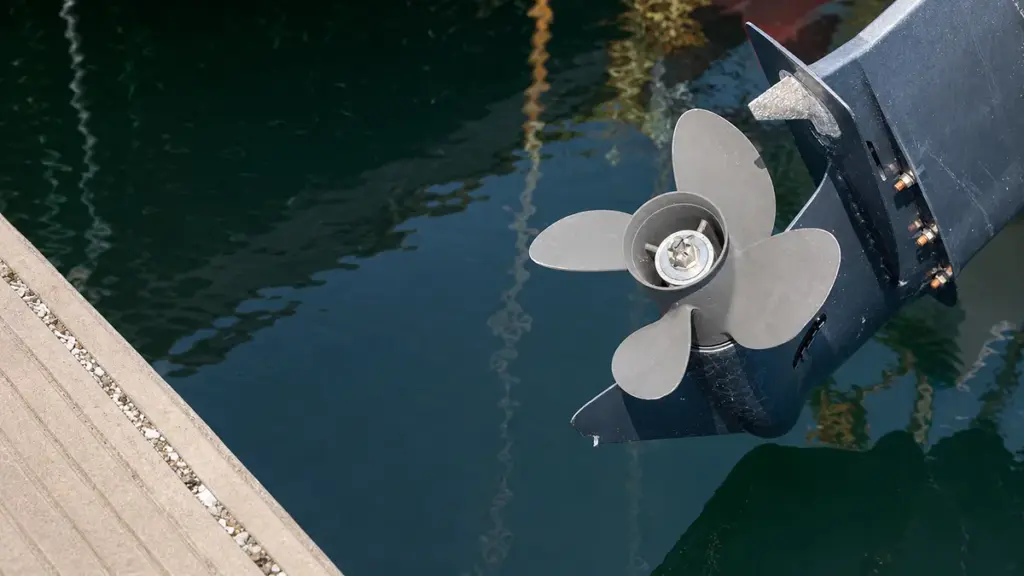
Propeller damage rarely announces itself with a catastrophic failure. It subtly degrades hydrodynamics, sending mechanical warnings through vibration, unusual noise, and sluggish performance that operators must decode.
The Mechanics of Propeller-Induced Vibration
Even minor propeller damage immediately disrupts hydrodynamic balance. When blades hit underwater objects, bent edges or missing metal shift the center of mass off the rotational axis. This mechanical imbalance forces the driveline to absorb cyclical stress.
- Center of mass shift: Bent blades or chipped edges create a mechanical imbalance away from the rotational axis.
- Hydrodynamic distortion: Altered blade geometry changes lift and thrust, placing uneven loads on the shaft and gears.
- RPM sensitivity: Vibrations peak at low to mid RPMs when the propeller works hardest to push the boat onto plane.
- Feedback transmission: Cyclical imbalances travel straight through the propshaft into the steering wheel, transom, and deck.
Translating Noise into Specific Driveline Issues
An outboard should produce a steady acoustic profile under load. When a propeller sustains damage, it introduces turbulence and mechanical interference that change the sound signature completely.
- Cavitation sounds: Damaged blades create low-pressure zones that spawn cavitation bubbles, producing distinct crackling, buzzing, or hissing noises.
- Engine stutter: Uneven thrust generation forces the motor to pulse audibly during hard acceleration runs.
- Lower unit rattle: Impact forces transfer directly into the lower unit, making gears and bearings rumble as they absorb the shock.
- Secondary wear indicators: Prolonged operation with an unbalanced prop causes propshaft bearings to grind or gearcases to emit a high-pitched whine.
Recognizing Performance Loss and Sluggish Acceleration
Physical damage directly compromises grip in the water. This hydrodynamic inefficiency forces the engine to burn more fuel while delivering less forward momentum.
- Increased propeller slip: Physical damage stops the efficient conversion of engine torque into actual forward thrust.
- Weak hole shot: A sluggish transition to plane serves as the primary indicator of blade distortion.
- Speed reduction: Minor imperfections trigger measurable drops in top speed and alter operating RPMs at specific throttle settings.
- Baseline comparison: Comparing current speed and wide-open throttle (WOT) RPM against historical metrics isolates propeller inefficiency from actual engine power loss.
Diagnostic Steps to Confirm the Root Cause
You cannot fix a driveline issue based purely on operator feel. Technicians rely on a strict diagnostic sequence to separate propeller damage from internal engine faults.
- 육안검사: Check the blades thoroughly for bends, nicks, gouges, 균열, or unequal marine growth.
- Shaft examination: Look at the prop shaft for visible bends, binding during manual rotation, or fishing line cutting into the seals.
- Isolation test: Run the engine safely in gear without the propeller installed to see if the vibration stops.
- Secondary component check: Evaluate engine mounts and fuel delivery systems if symptoms persist after installing a known-good propeller.
How to Inspect Blade Edges, Hub Area, and Shaft Contact
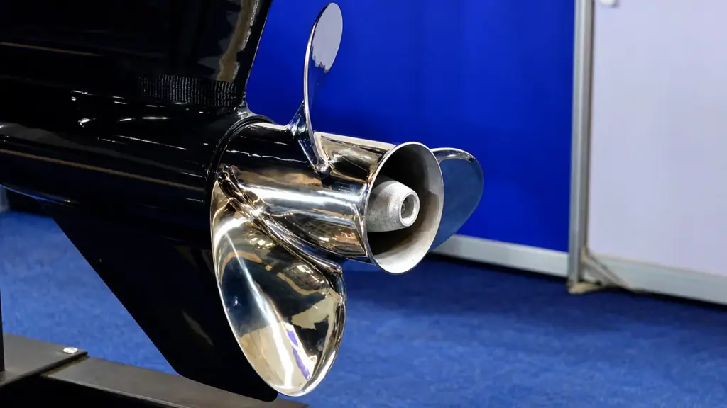
A systematic inspection of blade geometry, hub integrity, and shaft contact points prevents catastrophic lower unit failures, stops vibration, and ensures peak propulsive efficiency.
| Inspection Zone | Key Defect Indicators | Functional Impact |
|---|---|---|
| Blade Edges | Nicks, inward cracks, flattened cup | Hydrodynamic imbalance, cavitation, thrust loss |
| Hub Assembly | Extruded rubber, misaligned marker lines | Spun hub, complete loss of drive under load |
| 샤프트 & Hardware | Twisted splines, worn thrust washer | Fretting, gearcase vibration, thread damage |
Blade Edges and Surface Integrity
The geometry of the propeller blade dictates thrust generation and fuel efficiency. Technicians must examine leading edges, trailing edges, and tips for nicks, chips, gouges, or inward-radiating cracks. A damaged or flattened cupped trailing edge directly reduces water hold and increases the risk of early cavitation.
- Profile Consistency: Verify uniform rake angle and pitch across all blades to identify uneven bending or impact damage.
- Balance Check: Mount the propeller horizontally on a hub rod to identify heavy or off-plane blades.
- Clearance Limits: Ensure a minimum 3 mm tip clearance from the anti-cavitation plate to prevent contact under heavy load or blade flex.
Hub Area and Spun Hub Detection
The hub handles the brutal torque transfer from the engine to the water. A compromised rubber bushing acts as a failed mechanical fuse, dropping propulsion completely. Inspectors should check the outer hub barrel and blade roots for dents, ovalization, 아니면 가는선 균열. Extruded, melted rubber or heat staining clearly signals a failed bushing.
- Slippage Diagnostic: Draw a marker line across the outer housing, rubber zone, and inner hub, then run the boat under load to check for misalignment.
- Exhaust Path: Inspect internal routing for carbon build-up or structural obstructions that could disturb exhaust flow.
Prop Shaft and Hardware Contact Zones
The connection between the propeller and the driveline must remain perfectly aligned to avoid transferring destructive vibrations into the gearcase. Assess the propeller shaft for straightness, runout, 녹, and signs of pitting. Spline teeth on both the shaft and the hub bore require close inspection for rounding, chipping, or twisted profiles.
- Thrust Washer Integrity: Examine seating surfaces for cracks, uneven wear, or deep grooves that throw off propeller alignment.
- Torque Application: Apply the proper manufacturer-specified torque—commonly 40-60 ft-lbs—to prevent fretting or thread damage.
Integrated Inspection Workflow
A standard inspection workflow brings these discrete checks into a repeatable process. You must disable the engine ignition, remove the locking hardware, and safely slide the propeller off the shaft. Cleaning the shaft and hub bore with a degreaser is critical to accurately assess the splines and thrust washer without old marine grease hiding the defects.
- Component Evaluation: Systematically check the hub for spun bushing signs and the blade edges for profile consistency.
- Reassembly Protocol: Reinstall using fresh marine grease, pushing the prop forward until it clicks firmly against the thrust washer.
- Final Securing: Torque the nut to spec and verify the locking hardware is properly engaged.
When Minor Damage Can Still Be Repaired
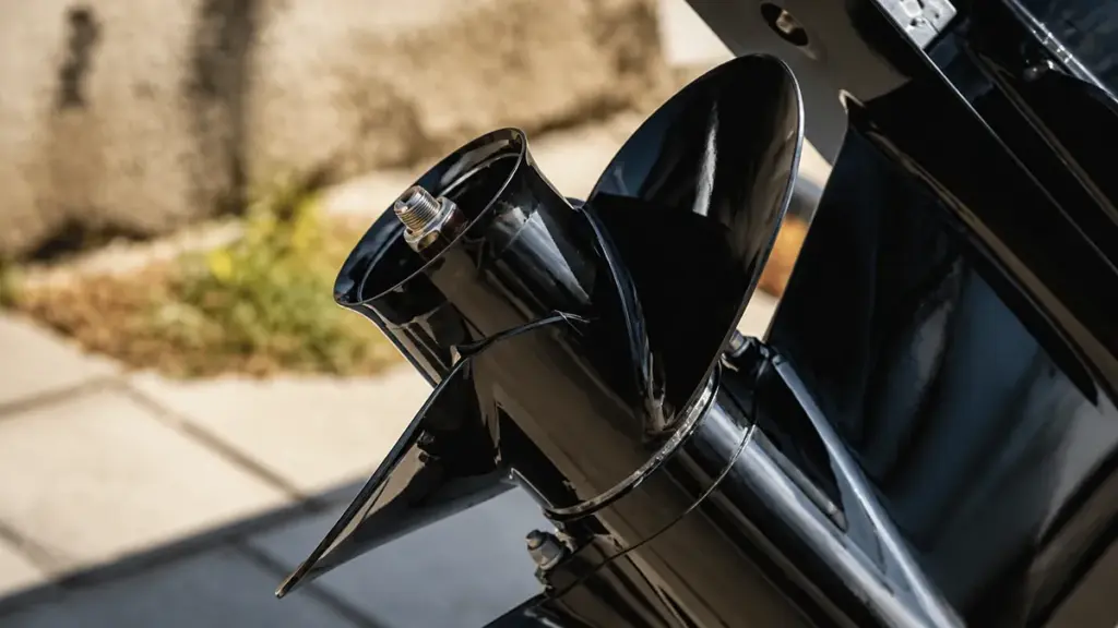
Minor propeller damage like edge burrs and shallow nicks can be repaired with basic filing, provided the blade geometry remains intact and no cracks or vibration are present.
Identifying Repairable Minor Damage
Before breaking out the tools, you need to confirm the damage is actually minor. Repairable defects are strictly surface-level flaws that do not compromise the structural integrity or hydrodynamic shape of the propeller.
- Surface-level dings: Small burrs, leading-edge nicks, and dents that leave the original blade geometry intact.
- Isolated edge wear: Damage limited entirely to the blade edges, meaning the overall diameter and pitch remain unchanged.
- Smooth operation: Propellers that continue to push the boat efficiently without inducing unusual vibration.
- Structural soundness: A complete absence of visible cracks or physical deformation during visual inspection.
If the propeller still performs well and the shaft runs true, you are likely dealing with cosmetic or minor edge wear.
Indicators of Severe Damage
Not all impacts result in a quick fix. Some structural flaws demand immediate professional intervention or a complete replacement to protect your gearcase.
- Visible cracks: Fractures in the blade or hub area, which usually require professional welding or replacement.
- Blade deformation: Noticeable bending or twist across one or multiple propeller blades.
- Severe vibration: Shaking immediately following an impact, signaling a potential mass imbalance.
- Drivetrain impact: Damage extending to the prop shaft, seal, or gear case after a hard strike.
- Die-cast limitations: Die-cast propellers displaying structural flaws, as marine professionals routinely classify these as non-repairable.
Operating with any of these severe defects transfers immense stress directly to your lower unit bearings and seals.
DIY Repair Methods and Discipline
Fixing minor edge damage requires precision and restraint. The goal is to smooth the water flow, not redesign the blade.
- Clean the propeller: Remove all marine growth, 흙, and oil to accurately assess the damage profile.
- File flat: Gently use a coarse or mill bastard file, keeping the tool flat to avoid reshaping the blade.
- Minimize removal: Take off only the absolute minimum amount of metal necessary to smooth out the burr or nick.
- Know when to stop: Cease filing the exact moment the raised metal disappears to preserve blade balance and efficiency.
- Polish the edge: Refine the filed area with fine sandpaper and polish it to reduce hydrodynamic drag and resist corrosion.
Over-filing a single blade shifts the center of mass, transforming a simple nick into a permanent vibration problem.
Deciding Between Repair and Replacement
Knowing when to stop trying to salvage a damaged propeller saves money and prevents unexpected breakdowns on the water.
- Owner repairs: Best suited for slight burrs and minor dings that need only light, controlled filing.
- Professional shops: Necessary for straightening bends, balancing, and checking for hidden cracks using dye or probe scanning.
- Replacement threshold: The smarter financial choice if repair costs exceed 50% of the propeller’s total replacement value.
- Spare recovery: Keeping a spare propeller onboard acts as the ultimate fail-safe if minor damage rapidly worsens during a trip.
Treat your propeller as a consumable wear part. Upgrading to a new unit is significantly cheaper than rebuilding a blown gearcase caused by running an unbalanced prop.
When Early Replacement Is the Safer Choice
Certain types of damage should not be repaired because they increase the risk of sudden failure.
Replacement is usually recommended under the following conditions.
| Damage Type | Replace Immediately? | Reason |
|---|---|---|
| Large blade cracks | 예 | High risk of blade separation |
| Missing blade section | 예 | Severe imbalance |
| Bent propeller shaft | 예 | Can damage gearbox |
| Multiple damaged blades | 예 | Difficult to restore accurately |
| Severe corrosion | 예 | Reduced structural strength |
| Repeated repaired cracks | 예 | Metal fatigue continues to grow |
Choose NEWTOP for Reliable Outboard Propeller Performance
A durable propeller begins with dependable manufacturing. ~에 뉴탑, we produce precision-balanced aluminum and stainless steel outboard propellers designed to deliver stable performance, 원활한 작동, and long service life across a wide range of marine applications.
Our manufacturing process combines advanced CNC machining, strict dimensional inspection, dynamic balancing, and comprehensive quality testing to ensure every propeller meets consistent performance standards before shipment. Whether you need replacement propellers for aftermarket distribution or OEM production for your own brand, NEWTOP offers flexible manufacturing solutions backed by reliable 생산 능력 and global export experience.
주요 이점은 다음과 같습니다.:
- CCS and ECE certified quality for reliable performance and international market requirements.
- Premium materials — aluminum propellers use specially formulated aluminum-magnesium alloy for high strength and toughness, while stainless steel propellers use duplex stainless steel with better yield strength and corrosion resistance.
- Integrated molding technology — propeller blanks are formed with dedicated molds without welding, improving structural strength and durability.
- Precision hub pressing and CNC machining — one-piece pressed hubs improve dynamic balance, while CNC-machined blades ensure consistent geometry and stable thrust performance.
If you’re looking for a trusted outboard motor propeller manufacturer for wholesale supply or customized production, contact NEWTOP today. Our engineering and production teams are ready to help you select the right propeller solution for your market while ensuring consistent quality and long-term supply.
자주 묻는 질문
선외 프로펠러가 손상되었는지 어떻게 알 수 있나요??
Look for visible bends, chips, 균열, or missing material on the blades. Operational signs include the engine revving unusually high without proportional boat acceleration, which often points to a spun hub. You might also notice persistent vibration, metallic noises, or a loss of steering stability at normal cruising speeds.
Can a small nick on a propeller cause vibration?
예, even a small nick alters the mass distribution and hydrodynamic symmetry of the blade. This physical imbalance generates centrifugal forces that manifest as noticeable vibration, often within a specific RPM band. Ignoring minor damage leads to progressive wear on the prop shaft and lower unit bearings.
What does a spun prop hub feel like?
A spun hub feels like the boat is slipping in the water. The engine RPM spikes sharply under throttle, but the boat’s speed does not increase. It mimics the sensation of a slipping automotive clutch and is sometimes accompanied by a sudden loss of thrust or a burnt rubber smell.
Should I repair or replace a chipped propeller?
Repair is usually viable for small edge chips or minor bends, especially on higher-value stainless steel props. Replace the propeller if it has large missing chunks, deep cracks near the root, or if you use a low-cost aluminum unit where repair expenses exceed half the price of a new replacement.
Can propeller damage reduce fuel efficiency?
Damaged blades increase hydrodynamic drag and disrupt smooth water flow, forcing the engine to work harder to maintain speed. This mechanical inefficiency prevents the motor from operating in its optimal RPM band, directly resulting in higher fuel consumption per nautical mile.
What kind of noise does a damaged propeller make?
A compromised prop typically produces a rhythmic knocking or thumping sound synchronized with engine RPM. You may also hear metallic rattling or a harsh, low-frequency drone from the lower unit, especially under heavy acceleration or during sharp turns.
Can I still run a boat with a bent propeller?
You should only operate a boat with a bent propeller at minimal idle power to safely return to the dock. Running at planing speeds with unbalanced blades creates severe radial loads that quickly destroy the prop shaft, 문장, and gearcase seals.
How often should I inspect my propeller?
Perform a quick visual and tactile check before and after every trip to spot obvious bends, chips, or wrapped fishing line. Complete a full removal inspection—taking the prop off to check the shaft, inspect seals, and re-grease the splines—at least once a season or every 100 hours of operation.
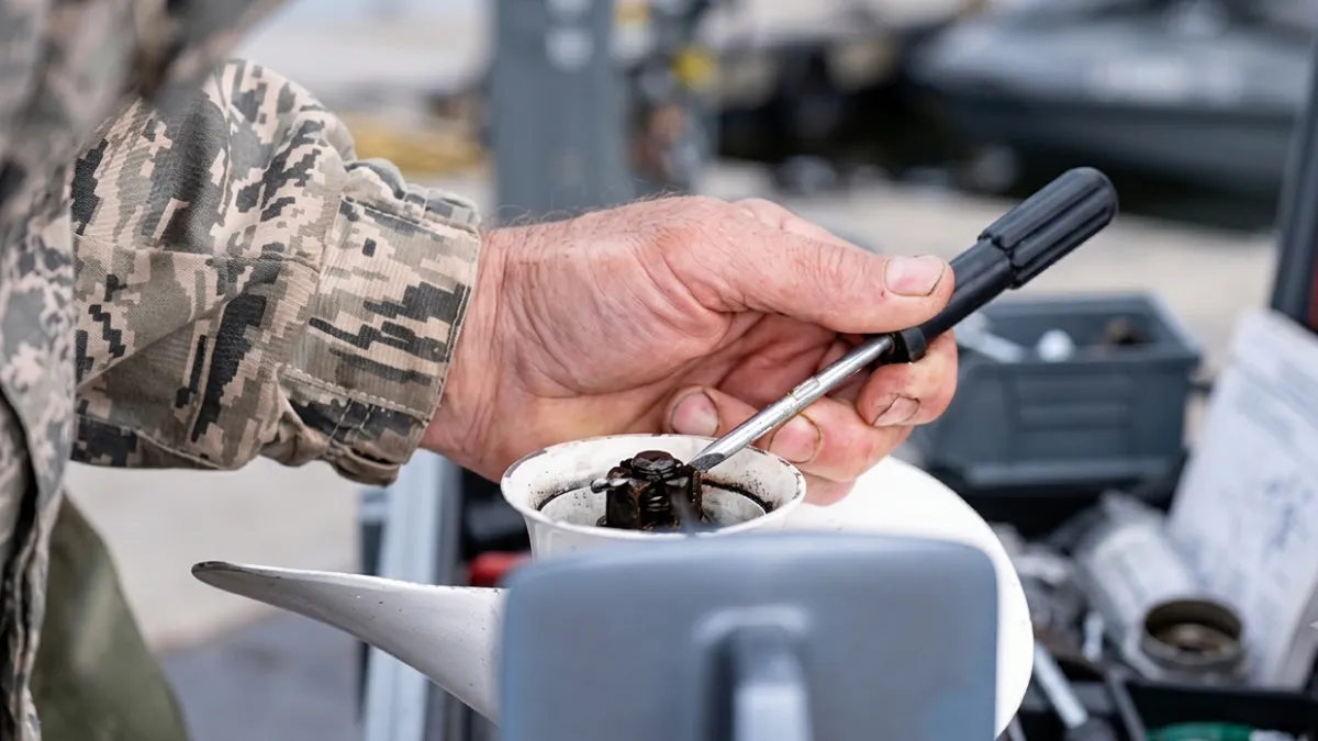
많은 보트 소유자는 보트의 느낌이 달라질 때까지 프로펠러 손상을 인지하지 못합니다.. 어쩌면 가속이 느려질 수도 있습니다, 연료비 증가, 또는 숨겨진 바위나 떠다니는 잔해물에 부딪혀 핸들이 진동하기 시작하는 경우. 조기 경고 신호를 알면 비용이 많이 드는 수리를 피하고 선외기를 효율적으로 작동하는 데 도움이 될 수 있습니다..
이 가이드에서는, 우리는 5 손상의 가장 흔한 징후 선외 프로펠러, 왜 중요한가, 프로펠러를 교체할 시기가 되었을 때.
손상된 프로펠러를 절대 무시해서는 안 되는 이유
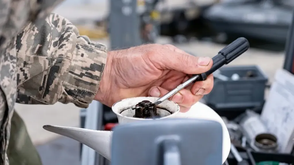
손상된 프로펠러를 무시하면 사소한 효율성 손실이 심각한 기어케이스 손상으로 이어집니다., 치솟는 연료비, 위험한 취급 문제. 엔진과 지갑을 보호하려면 조기에 수정하세요..
성능 저하 및 처리 문제
프로펠러가 손상되면 보트의 설계 성능이 즉시 저하됩니다.. 사소한 블레이드 왜곡조차도 엔진 출력을 효율적인 전진 동작으로 변환하는 데 필요한 유체 역학 프로필을 손상시킵니다.. 운영자는 일반적으로 이를 느린 홀 샷과 눈에 띄는 최고 속도 저하로 인식합니다..
- 추력 손실: 구부러지거나 부서진 블레이드는 형상을 방해합니다., 전방 추력이 감소하고 가속력이 저하됩니다..
- 불안정성 처리: 불규칙한 블레이드 표면으로 인해 고르지 않은 추력이 발생합니다., 스티어링 풀로 이어지는, 불안정한 트림, 일관성 없는 추적.
- 진동 발생: 균형이 맞지 않는 회전은 하중을 받을 때 진동을 발생시킵니다., 종종 활주 속도로 데크를 통과하는 리드미컬한 쿵쿵거리는 느낌이 들었습니다..
연료 소비 및 운영 비용 증가
손상된 프로펠러를 실행하면 운영 예산이 직접적으로 공격을 받습니다.. 블레이드 표면의 결함으로 인해 층류의 물 흐름이 파괴됩니다., 그것을 항력과 난기류로 대체. 표준 순항 속도에 도달하려면 엔진이 훨씬 더 많은 연료를 소모해야 합니다..
- 드래그 추가: 손상된 블레이드로 인해 난류 발생, 추진력을 유지하기 위해 엔진이 더 열심히 작동하도록 강요.
- 더 높은 연료 연소: 찌그러지거나 구부러진 프로펠러는 일반적으로 전체 연료 소비를 대략적으로 증가시킵니다. 10%.
- 스로틀 보상: 운전자는 비효율적인 추력을 상쇄하기 위해 자연스럽게 스로틀을 더 세게 밀어냅니다., 일상적인 운영 비용을 조용히 증가시킵니다..
하부 장치에 심각한 기계적 응력이 가해짐
외부의 외관상 손상은 내부의 심각한 기계적 손상을 숨기는 경우가 많습니다.. 불균형 프로펠러는 드라이브트레인에 망치처럼 작용합니다.. 끊임없이 보낸다, 주기적 스트레스가 하위 단위로 직접 전달됨, 저렴한 소품 수리를 대규모 기어케이스 재구축으로 전환.
- 기어케이스 마모: 고르지 않은 하중은 응력을 하부 장치에 직접 전달합니다., 기어를 파괴하다, 문장, 그리고 샤프트가 조기에.
- 씰 성능 저하: 지속적인 진동으로 인해 프롭 샤프트 씰이 찢어짐, 기어 오일이 새고 물이 유입될 수 있습니다..
- 샤프트 정렬불량: 블레이드를 변형시키는 강한 충격으로 인해 프로펠러 샤프트가 자주 구부러집니다., 확인하지 않은 채 방치하면 치명적인 오류가 발생함을 보장합니다..
안전 위험 및 좌초 가능성
손상된 지지대를 사용하여 작동하면 안전 여유가 위험 영역으로 밀려납니다.. 깨끗한 추력의 손실로 인해 좁은 구역이나 거친 조건에서 선박을 예측할 수 없게 됩니다.. 손상된 드라이브트레인을 해외로 밀면 전력이 가장 필요할 때 갑작스러운 기계적 고장이 발생할 수 있습니다..
- 도킹 위험: 역추력 손실과 불규칙한 핸들링으로 인해 좁은 채널과 미끄러짐 주변에서 기동 제어가 불가능해집니다..
- 고장 위험: 기존 손상을 입은 채로 달리면 진행 중에 갑작스러운 기계적 고장이 발생할 확률이 급격히 높아집니다..
- 날씨 취약성: 추진 효율 감소로 인해 거친 바다를 항해할 때 안전 마진이 손상됩니다., 강풍, 아니면 강한 조류.
5 손상된 외부 프로펠러 목록의 징후
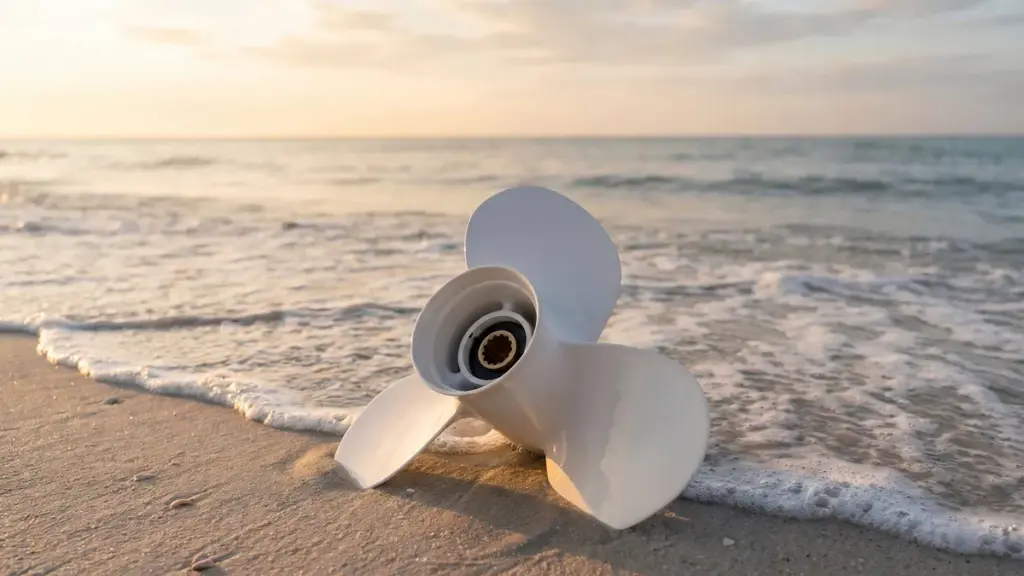
선외기가 갑자기 진동하는 경우, 속도를 잃다, 또는 평소보다 더 많은 연료를 소비합니다., 프로펠러가 이미 손상되었을 수 있습니다. 아래 표에는 가장 일반적인 증상이 요약되어 있습니다., 그들의 가능한 원인, 엔진에 어떤 영향을 미칠 수 있는지.
| 경고 표시 | 주요 원인 | 즉각적인 위험 |
|---|---|---|
| 진동 | 구부러진 블레이드 또는 느슨한 허브 | 기어케이스 밀봉 불량 |
| 속도 손실 / 불쌍한 홀샷 | 회전 허브 또는 블레이드 드래그 | 엔진 러깅 |
| 소음 / 스티어링 불안정성 | 비대칭 블레이드 또는 구부러진 샤프트 | 하부 기어 손상 |
| 높은 연료 사용 / 짐 | 유체역학적 항력 | 피스톤 및 냉각 시스템 마모 |
| 눈에 보이는 손상 | 충격파 | 구동계에 대한 충격 하중 |
징후 1: 가속 또는 순항 중 진동
손상된 프로펠러는 제대로 회전하는 경우가 거의 없습니다.. 조종 장치를 통해 직접 느껴지는 흔들림을 느낄 수 있습니다., 선외 모터 하우징, 아니면 보트 선체 자체, 특히 가속하거나 일정한 순항 속도를 유지할 때. 이러한 진동은 프로펠러 효율성을 크게 감소시키고 엔진 마운트와 기어케이스 씰에 즉각적인 스트레스를 가합니다..
- 일반적인 원인: 구부러지거나 뒤틀린 칼날, 느슨한 허브, 또는 프로펠러 샤프트 주위에 오염된 무거운 잔해물.
- 실행 가능한 점검: 엔진을 끄고 소품을 점검하십시오.. 블레이드 각도를 확인하여 일치하는지 확인하세요., 그런 다음 프로펠러를 손으로 돌려 기어케이스에 긁힌 자국이나 흔들림이 있는지 확인합니다..
징후 2: 속도 저하 및 홀샷 불량
느린 가속, 비행기 탑승 시간이 눈에 띄게 느려짐, 추진력 비효율성과 직접적으로 최고 속도 지점을 감소시켰습니다.. 엔진 RPM이 정상이거나 상승된 경우에도, 손상된 프로펠러는 그 동력을 전방 추력으로 변환하지 못합니다.. 이는 손상된 블레이드 가장자리 주변의 캐비테이션이나 과도한 항력을 생성하는 과도한 해양 오염으로 인해 발생하는 경우가 많습니다..
- 회전 허브 표시기: 내부 부싱이 파손된 경우, 완전한 엔진 토크를 물에 전달할 수 없습니다., 최소한의 보트 움직임으로 높은 RPM 발생.
- 실행 가능한 점검: 현재 활짝 열린 스로틀을 비교하세요 (WOT) 선박의 과거 기준 데이터에 대한 RPM 및 최고 속도.
징후 3: 비정상적인 소음 또는 스티어링 불안정성
새로운 허밍, 활발한, 또는 갈리는 소음은 심각한 기계적 정렬 불량을 나타냅니다., 특히 특정 RPM 범위를 회전하거나 통과할 때. 조타 장치가 조종하기 더 어렵게 느껴지거나 한쪽으로 심하게 당겨지는 것을 볼 수도 있습니다.. 비대칭이기 때문에 이런 일이 발생합니다., 구부러진 블레이드는 고르지 않은 추력을 생성합니다., 보트를 자연적인 추적 경로에서 벗어나게 하는 것.
- 기어케이스 위협: 지속적인 연삭은 일반적으로 이전 수중 타격으로 인해 구부러진 프롭 샤프트 또는 하부 장치 기어 손상을 나타냅니다..
- 실행 가능한 점검: 프로펠러를 앞뒤로 흔들어 과도한 유격을 감지합니다.. 손으로 돌리면서 내부에서 긁히는 소리가 들리는지 자세히 들어보세요..
징후 4: 높은 연료 사용 및 비정상적인 엔진 부하
연료 효율이 갑자기 떨어지면 정확히 동일한 경로와 적재량을 위해 주유소에 더 자주 정차하게 됩니다.. 블레이드 손상이나 오염으로 인한 유체 역학적 항력으로 인해 손실된 추력과 진동을 극복하기 위해 엔진이 더 열심히 작동하게 됩니다.. 엔진 소리가 긴장되고 정상적인 순항 속도를 유지하려면 더 높은 스로틀 설정이 필요합니다..
- 장기간 착용: 이러한 고하중 조건에서 지속적인 작동으로 인해 피스톤 마모가 가속화됩니다., 문장, 및 외부 냉각 시스템.
징후 5: 보이는 칼날, 바퀴통, 또는 가장자리 손상
물리적 결함은 영향을 나타내는 가장 확실한 지표입니다.. 빠른 육안 검사를 통해 종종 흠집이 발견되는 경우가 많습니다., 팁이에요, 누락된 청크, 아니면 가는선 균열. 이러한 결함은 일반적으로 보트가 접지되거나 암석에 부딪히면서 발생합니다., 모래톱, 암초, 아니면 물에 잠긴 잔해물. 사소한 물리적 손상이라도 프롭의 효과적인 피치와 균형을 변경합니다., 유해한 충격 부하를 하부 장치에 직접 전달.
- 실행 가능한 점검: 프로펠러를 제거하여 모든 표면을 면밀히 검사하십시오.. 심각한 구조적 손상이 발견되거나 수리 견적이 초과된 경우 장치를 교체하십시오. 50% 새 소품 비용 중.
고성능 OEM 선외 프로펠러 공급

적시에 적절한 프로펠러를 교체하여 엔진을 보호하는 방법
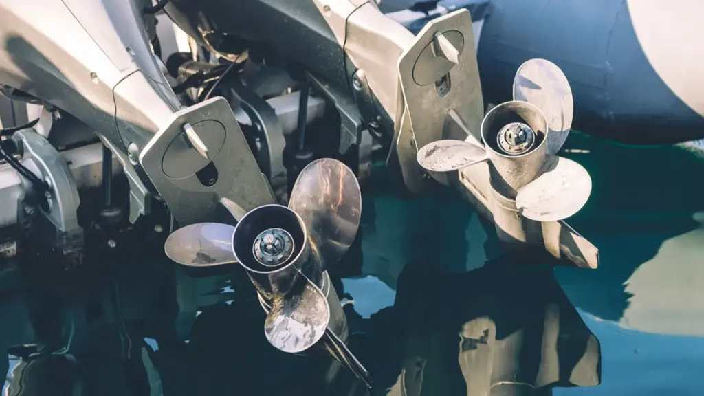
프로펠러가 손상되면 엔진이 더 열심히 작동하게 되고 심각한 드라이브트레인 고장의 위험이 있습니다.. 손상된 장치를 교체하면 기어 케이스가 즉시 보호되고 기본 연료 효율성이 복원됩니다..
교체 시기 식별
프로펠러 교체 시기를 정확히 알면 경미한 마모가 기계적 고장으로 확대되는 것을 방지할 수 있습니다.. 시각적 및 촉각적 검사가 첫 번째 방어선 역할을 합니다.. 물에 잠긴 물체에 충격을 가할 경우 즉각적인 주의가 필요합니다., 배는 계속 움직이고 있어도.
- 눈에 보이는 구조적 손상: 깊은 균열이 있는지 확인하세요., 누락된 큰 덩어리, 심하게 구부러진 칼날, 또는 블레이드 형상을 손상시키는 가장자리가 얇아짐.
- 기준 성능 저하: 갑자기 기본 스로틀 개방에 도달하지 못하는 엔진을 조심하세요. (WOT) 일반 부하에서 RPM 또는 최고 속도.
- 진동 및 취급 문제: 지속적인 진동, 스티어링 풀, 또는 거친 추적은 프로펠러의 균형이 맞지 않음을 나타냅니다..
- 충격 후 확인: 수중 암석에 부딪힌 후 샤프트와 씰을 검사하기 위해 항상 지지대를 제거하십시오., 로그, 또는 잔해.
올바른 교체 프로펠러 선택
일치하지 않는 프로펠러를 설치하는 것은 부러진 프로펠러를 작동하는 것만큼 손상됩니다.. 교체 사양을 선체 유형 및 일반적인 작동 부하에 맞게 조정해야 합니다..
- 올바른 피치와 직경: 제조업체가 권장하는 피치 범위가 누락되면 엔진이 과도하게 회전하거나 러그됩니다., 연비와 가속력을 파괴합니다..
- 충격흡수용 알루미늄: 알루미늄 소품은 얕은 곳에서 희생적인 장벽 역할을 합니다., 위험이 높은 물. 충격을 받으면 변형됩니다., 값비싼 기어케이스에 충격을 훨씬 적게 전달.
- 내구성을 위한 스테인레스 스틸: 최대의 효율성이 필요할 때 스테인리스 스틸을 선택하세요, 굴곡 저항, 깊은 물이나 위험이 없는 물에서의 내구성.
설치 및 교체 후 점검
성공적인 교체를 위해서는 허브 어셈블리 및 샤프트 환경에 대한 엄격한 주의가 필요합니다.. 새 프로펠러를 밀어 넣기 전에, 드라이브라인이 올바르게 작동하는지 확인하기 위해 해당 부위를 철저히 청소하고 준비하십시오..
- 샤프트 준비: 감겨있는 낚싯줄을 벗겨내세요, 잡초, 새 봉인을자를 수있는 잔해물.
- 하드웨어 좌석: 스플라인에 해양 등급 그리스를 바릅니다.. 과도하게 조이지 않고 정확한 토크 사양에 따라 프롭 너트를 고정합니다., 디자인에 필요한 경우 새 코터 핀을 삽입하십시오..
- 마찰 테스트: 바깥쪽 보드를 중립으로 전환하고 새 프로펠러를 손으로 회전시킵니다.. 기어케이스를 묶거나 긁지 않고 자유롭게 회전해야 합니다..
- 기준 검증: 새로운 프로펠러가 원래의 최고 속도와 WOT RPM을 복원하는지 확인하기 위해 정상적인 부하에서 보트를 실행하십시오..
결론
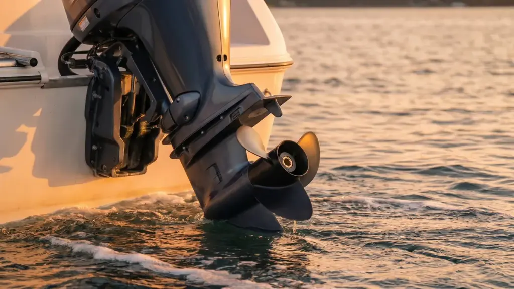
정기적인 검사와 적시 교체가 선외기 엔진을 보호하는 최선의 방법입니다., 보트 성능 향상, 장기적인 운영 비용 절감. 올바른 피치의 선외 모터 프로펠러를 공급하는 것도 마찬가지로 중요합니다., 지름, 안정적이고 효율적인 작동을 보장하는 고품질 재료.
자체 항공기의 프로펠러를 교체하든, 비즈니스를 위해 제품을 소싱하든 상관없습니다., 경험이 풍부한 선외 모터 프로펠러 제조업체와 협력하면 제품 품질에 상당한 차이를 만들 수 있습니다., 성능, 장기적인 신뢰성. ~에 뉴탑, 당사의 통합 선외 모터 프로펠러 공장은 첨단 제조와 유연한 OEM/ODM 서비스를 결합하여 유통업체와 해양 브랜드가 경쟁 시장에서 성공할 수 있도록 지원합니다..
👉 지금 NEWTOP에 문의하세요 OEM 또는 도매 요구 사항을 논의하고 다음 선외 프로펠러 프로젝트에 대한 경쟁력 있는 견적을 받으려면.
자주 묻는 질문
손상된 선외 프로펠러의 징후는 무엇입니까??
시각적 결함을 통해 프로펠러 손상을 확인할 수 있습니다., 성능 저하, 그리고 기계적 증상. 찌그러진 부분을 찾아보세요, 구부러진 칼날 팁, 누락된 청크, 또는 허브 근처에 미세한 균열이 있음. 물 위에, 손상은 더 느린 최고 속도로 나타납니다., 느린 홀샷, 낮은 전진 보트 속도와 높은 엔진 RPM. 또한 조타 장치에서 새로운 리드미컬한 진동을 느끼거나 쿵쿵거리는 소리가 들릴 수도 있습니다.. 하부유닛 주변에서 우유빛 기어오일이 새는 것을 발견한 경우, 충격으로 인해 프롭 샤프트 씰이 손상되었을 가능성이 있음.
프로펠러가 손상되면 엔진이 손상될 수 있나요??
예, 손상된 프로펠러는 선외기 엔진 전체와 하부 장치에 심각한 스트레스를 가합니다.. 블레이드가 조금만 구부러져도 불균형한 회전이 발생합니다.. 이러한 회전 불균형은 지속적으로, 드라이브라인을 직접 통과하는 심한 진동. 선택하지 않은 상태로 둡니다, 이 흔들림으로 인해 프로펠러 샤프트 씰이 파손될 때까지 망치로 쳐집니다., 기어 윤활유가 새고 물이 유입되도록 놔두기. 이 상태에서 엔진을 작동하면 기어 세트와 베어링의 금속 간 마모가 빠르게 발생합니다..
물속에 있는 물체에 부딪힌 후 보트가 진동하는 이유는 무엇입니까??
물에 잠긴 물체에 부딪히면 구동계의 균형이 깨집니다.. 충격은 일반적으로 프로펠러 블레이드를 구부립니다., 재료를 잘라내다, 또는 프로펠러 샤프트가 약간 구부러집니다.. 프로펠러가 더 이상 대칭 모양을 유지하지 않거나 완벽하게 회전하기 때문에, 원활하게 회전하지 않고 궤도를 돌고 있습니다.. 이 흔들림은 바깥쪽 다리 바로 위로 이동하는 리드미컬한 흔들림 힘을 생성합니다., 엔진 마운트를 통해, 그리고 선체에 직접.
프로펠러 손상으로 인해 가속 성능이 저하될 수 있음?
예. 물리적 손상으로 인해 블레이드 피치가 변경됩니다., 캠버, 그리고 컵. 이러한 왜곡으로 인해 프로펠러의 유체역학적 효율성이 저하됩니다., 물에 대한 그립력을 잃게 만들고 전방 추력을 대폭 감소시킵니다.. 또한, 강한 충격으로 인해 내부 고무 허브가 손상되는 경우(일반적으로 “회전 허브”—프로펠러 쉘이 샤프트에서 미끄러짐. 스로틀을 밟았을 때, 보트가 거의 가속하지 않거나 비행기에 오르기 위해 애쓰는 동안 엔진 회전수가 높아집니다..
나쁜 프로펠러로 인해 연료 소비가 증가합니까??
예. 손상된 프로펠러를 작동하면 엔진이 마일당 더 많은 연료를 소모하게 됩니다.. 굽은, 부서진, 또는 심하게 오염된 블레이드는 추가적인 유체 역학적 항력을 생성하고 프로펠러 미끄러짐을 증가시킵니다.. 손상된 블레이드는 엔진 토크를 효율적으로 추력으로 변환할 수 없기 때문에, 아웃보드는 정상적인 순항 속도를 유지하기 위해 더 빠르게 회전하고 훨씬 더 열심히 작동해야 합니다.. 한 시즌에 걸쳐, 이러한 비효율성은 상당히 높은 연료비를 발생시킵니다..
손상된 프로펠러를 언제까지 안전하게 사용할 수 있나요??
손상된 프로펠러는 저속으로 절뚝거리며 부두로 돌아올 수 있을 만큼만 작동해야 합니다.. 진동 작동, 오랜 기간 동안 불균형한 소품으로 인해 비정상이 발생합니다., 하부 유닛 베어링 및 씰에 대한 주기적 응력. 이 상태에서 엔진을 밀면 간단한 문제가 빠르게 확대됩니다., 저렴한 프로펠러를 치명적인 기어케이스 재구축으로 교체.
손상된 허브로 인해 엔진이 과도하게 회전할 수 있습니까??
예. 제조업체는 하부 장치 기어가 전단되는 것을 방지하기 위해 심한 충격 중에 미끄러지도록 내부 고무 허브를 설계합니다.. 이 허브가 회전하거나 찢어지면, 외부 프로펠러 쉘에 대한 꽉 고정력을 영구적으로 잃습니다.. 스로틀을 적용하면, 토크를 전달하는 대신 손상된 허브가 미끄러집니다.. 이를 통해 보트를 앞으로 밀지 않고도 엔진 RPM이 빠르게 급증할 수 있습니다., 미끄러지는 변속기의 느낌을 모방.
예비 프로펠러를 기내에 보관해야 하나요??
예비 프로펠러를 기내에 보관하는 것이 좋습니다.. 저렴한 보험 역할을 합니다., 특히 알루미늄 프로펠러를 사용하거나 정기적으로 얕은 곳을 탐색하는 경우, 장애물로 가득 찬 물. 예비 유닛 운반, 프롭 렌치와 함께, 교체 스러스트 와셔, 그리고 신선한 코터핀, 손상된 소품을 그 자리에서 교체할 수 있습니다.. 이를 통해 즉시 안전한 추진력을 복원하고 망가진 주말이나 값비싼 견인 비용을 절약할 수 있습니다..
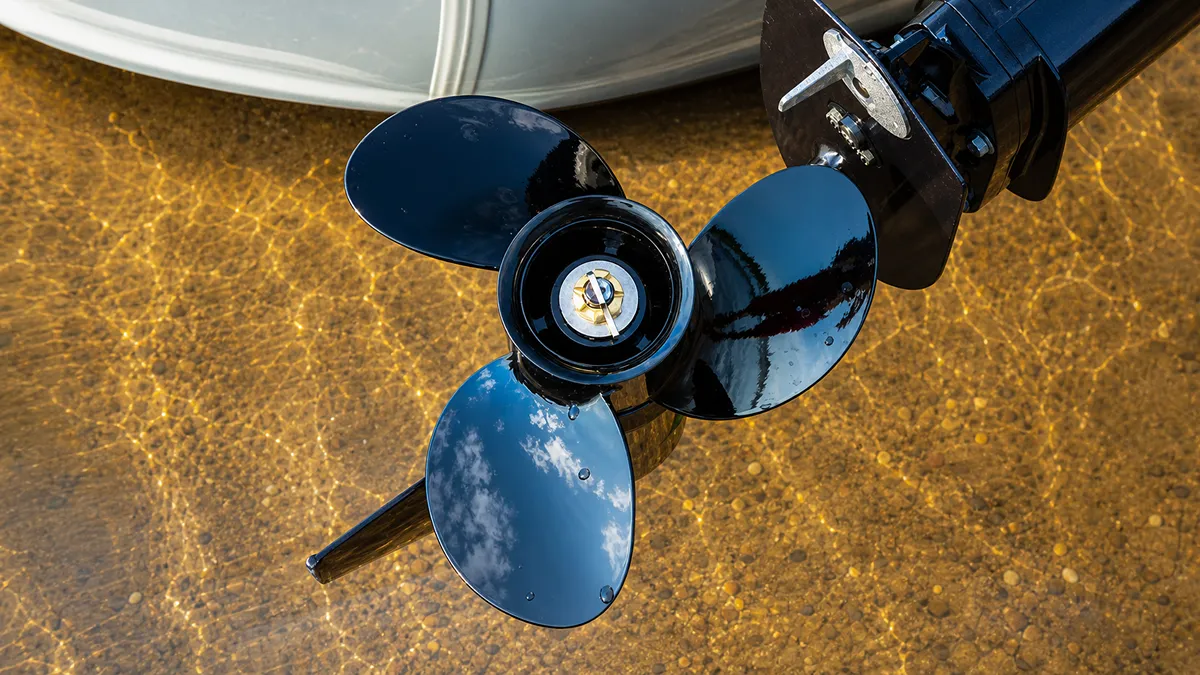
When a boat suddenly loses thrust, engine RPM rises without matching acceleration, or the 추진자 shows unusual surface damage, many operators assume the propeller is simply worn out. 실제로는, the problem may be propeller cavitation.
Cavitation is one of the most misunderstood issues affecting outboard motor performance. It reduces efficiency, increases fuel consumption, shortens propeller life, and may even lead to expensive repairs if ignored. Although it is often confused with ventilation, the two problems have different causes and require different solutions.
이 가이드에서는, we’ll explain what cavitation is, what causes it, how it affects your boat, and the practical ways to prevent it by choosing the right propeller and setup.
What Is Cavitation in Outboard Motor Propellers?
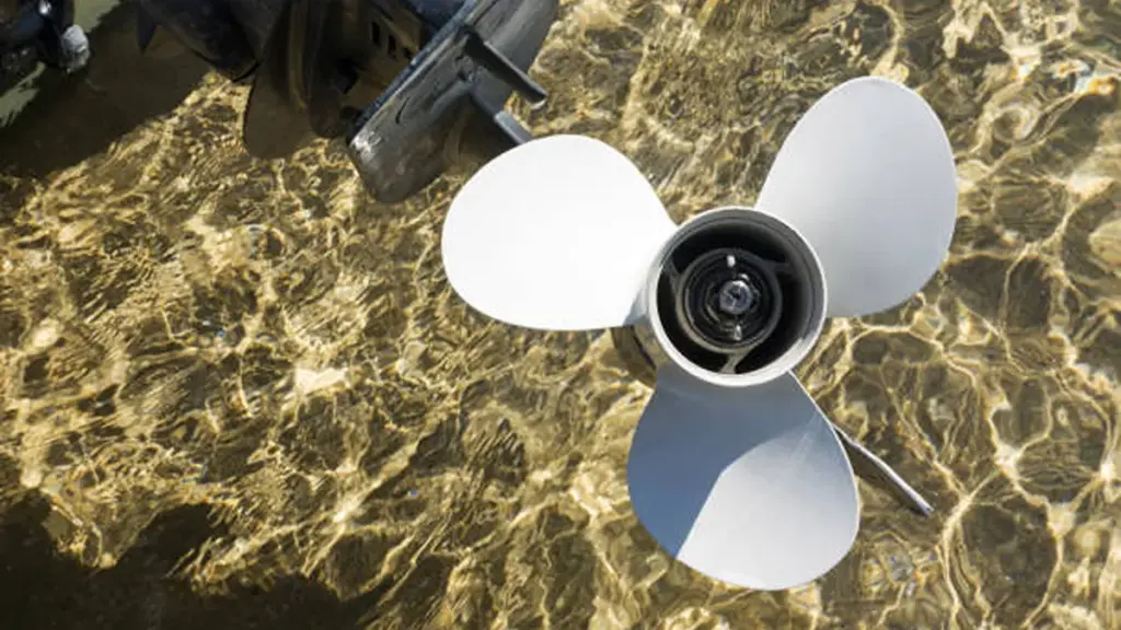
Cavitation in outboard propellers is a destructive hydrodynamic pressure issue. Vapor bubbles form and violently collapse on the blades, causing power loss and severe metal erosion.
The Physical Process of Cavitation
Cavitation starts when rapid propeller rotation forces local water pressure to drop below its vapor pressure. This extreme low pressure triggers an immediate phase change, creating vapor bubbles directly on the blade surface. The water essentially boils at ambient temperature due to the pressure drop.
As the spinning propeller drives these vapor bubbles into higher-pressure zones, they cannot sustain their form and collapse violently. These collapsing bubbles release intense micro-shock waves against the blade. 시간이 지남에 따라, these repeated impacts pound the metal surface, eroding the material and causing severe pitting.
Common Causes in Outboard Setups
Several setup and operational factors create the ideal environment for these damaging low-pressure zones to form.
- Incorrect mounting and trim: Setting the engine mounting height too high or trimming the motor out too far disrupts solid water flow across the blades.
- Poor propeller selection: Using a propeller poorly matched to the boat’s hull, load, or engine power forces the blades to carry excessive hydrodynamic load.
- Pre-existing damage: Bent blades, over-filed tips, or nicked edges create uneven hydrodynamics that trigger localized pressure drops.
- Disturbed inflow: Hull turbulence, transducers, or underwater obstructions prevent clean water from reaching the lower unit.
Symptoms and Performance Impacts
Operators usually identify cavitation through immediate handling degradation and eventual mechanical wear on the propulsion system.
- Loss of thrust: You experience a sudden decrease in power transfer efficiency, leaving the boat feeling sluggish under heavy throttle.
- RPM flaring: The engine speed surges rapidly without a proportional increase in forward acceleration.
- Audible disturbances: Collapsing bubbles create a distinct gravel-like rattling, accompanied by excessive vibration through the transom.
- Cumulative wear: Unchecked cavitation leads to visible blade erosion, pitting, and structural metal fatigue over time.
Distinguishing Cavitation from Ventilation
Boaters frequently confuse cavitation with ventilation, but they are entirely different mechanical events. Cavitation functions strictly as a hydrodynamic pressure issue resulting in vaporized water. Ventilation happens when the propeller physically pulls surface air or exhaust gases directly into the slipstream.
Both phenomena create nearly identical operator symptoms, including sudden RPM flare and an immediate loss of bite in the water. Accurate diagnosis dictates the repair path. Fixing ventilation usually involves basic trim adjustments or dropping the engine height. Resolving cavitation often requires repairing damaged blade edges or selecting a completely different propeller design to handle the engine’s output.
How Cavitation Differs from Ventilation
Cavitation is a pressure-induced phase change causing water to boil and erode propeller blades, while ventilation is external air getting sucked into the prop wash, causing sudden slippage.
Many boat owners use the terms cavitation 그리고 ventilation interchangeably, but they describe two different phenomena.
| 특징 | Cavitation | Ventilation |
|---|---|---|
| Cause | Water pressure drops below vapor pressure. | Air enters the propeller blades. |
| Medium Around Blade | Water vapor bubbles. | Air from above the water surface. |
| Main Symptom | Blade erosion and reduced propulsion efficiency. | Sudden engine RPM increase with poor thrust. |
| Blade Damage | 예, often causes pitting and surface erosion. | Usually no direct blade erosion. |
| Typical Causes | Incorrect blade loading, damaged propeller, poor blade design, or excessive pressure drop. | Engine mounted too high, sharp turns, rough water, or excessive trim angle. |
A simple way to remember the difference:
- Cavitation creates bubbles from water.
- Ventilation pulls air into the propeller.
Maximize Margins With Professional-Grade Garden Machinery
The Main Causes of Propeller Cavitation
Cavitation occurs when local water pressure drops below vapor pressure. Excessive speed, mismatched propellers, blade damage, and disturbed inflow from poor setup are the primary triggers.
| Cavitation Cause | Primary Mechanism |
|---|---|
| 속도 & 로드 중 | High RPM and heavy vessel loads drive local pressure below the vapor threshold. |
| Propeller Mis-Match | Wrong pitch or physical size creates extreme pressure imbalances across the blade. |
| Blade Damage | Nicks and bent edges prevent smooth water flow, causing localized low-pressure zones. |
| Setup & Inflow | Improper engine height or hull obstructions introduce turbulent, low-pressure water. |
Excessive Propeller Speed and High Loading
Propellers designed for standard operation struggle when pushed past their hydrodynamic limits. Spinning a blade too fast creates an extreme pressure drop on the back side. This sudden vacuum forces the water to vaporize instantly into gas pockets.
Operating parameters heavily influence this pressure shift. Specific stressors force the propeller into a continuous cavitation cycle.
- Heavy loads: Excess vessel weight forces the engine to work harder, multiplying blade stress.
- Hard acceleration: Rapid throttle spikes disrupt steady water flow and immediately drop local pressure.
- Extreme RPMs: Sustained high-speed operation with an overloaded vessel guarantees continuous vapor formation.
Incorrect Pitch, Sizing, and Propeller Mis-Match
Slapping any available propeller onto an outboard guarantees poor performance. Pitch directly dictates blade loading. Excessive pitch bogs down the engine and overloads the blades at lower speeds. Insufficient pitch lets the engine over-rev, accelerating the blades so fast that they tear the water apart and induce surface cavitation.
Proper matching requires aligning the propeller geometry with the specific vessel dynamics to maintain pressure equilibrium.
- Diameter constraints: Selecting a size that ignores hull weight and horsepower creates severe pressure imbalances.
- Blade geometry: The wrong blade count, rake, or cup strips the propeller of its grip, increasing slip and flow separation.
- Hull compatibility: A propeller style mismatched to the hull design fails to handle the specific water flow of that vessel.
Physical Blade Damage and Surface Imperfections
Water requires a perfectly smooth surface to maintain laminar flow. Minor impact damage alters the local hydrodynamics completely. Nicks, gouges, or missing chunks on the leading edge stop the blade from slicing cleanly. These defects act as turbulence generators, spawning localized low-pressure zones where vapor bubbles rapidly form.
Physical irregularities consistently trigger flow breakdown across the entire propulsion system.
- Bent blades: Asymmetric geometry causes uneven loading and violent pressure swings during every revolution.
- Altered edges: Overly sharpened or blunt leading edges detach the water flow prematurely.
- Lower unit fouling: Barnacle buildup or deep scratches on the gearcase destroy the clean water stream before it reaches the blades.
Disturbed Inflow, Setup, and Clearance Issues
A propeller operates efficiently only when fed a steady stream of dense, clean water. Mounting the outboard too high on the transom starves the system. This setup places the blades near the surface where the water is already aerated and low in pressure, accelerating the phase change into vapor.
Environmental factors around the transom dictate the quality of the inflow reaching the propeller.
- Clearance limits: Inadequate spacing between the propeller, hull bottom, and skeg amplifies local turbulence.
- Appendage drag: Poorly placed transducers or water pickups inject chaotic currents directly into the propeller path.
- Vessel attitude: Excessive stern weight or improper boat trim shifts the inflow angle, severely degrading water density.
How Cavitation Affects Speed, Fuel Use, and Blade Life
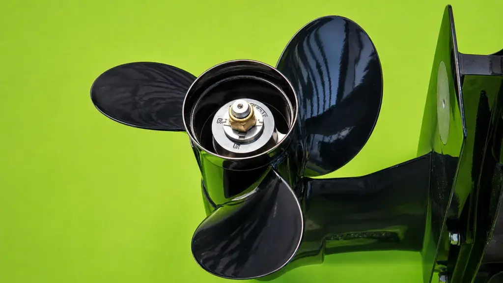
Cavitation cripples propeller efficiency. It kills top speed, burns up to 10% more fuel per mile, and destroys blades through violent micro-shock waves, forcing expensive premature replacements.
Impact on Boat Speed and Acceleration
When cavitation vapor bubbles form, they reduce effective blade lift. This breaks the propeller’s physical hook-up to the water and causes a massive drop in thrust. You will often feel this as a sudden RPM flare with barely any forward movement, forcing you to back off the throttle to let the blades regain bite.
- Hole-Shot Performance: Acceleration becomes sluggish, drastically extending the time it takes to get the heavy hull on plane.
- Top Speed Penalty: Even partial tip cavitation creates enough drag to cause a 2–5% loss in top speed on high-performance setups.
Increased Fuel Consumption and Reduced Efficiency
Vapor bubbles sticking to the blade surfaces act like a physical barrier. They increase friction and alter the effective thickness of the blade, destroying hydrodynamic efficiency. To compensate for the lost thrust, operators push the throttle further forward. This pushes the engine into a higher RPM band where it operates far outside its peak fuel efficiency range.
- Burn Rate: A chronic cavitation mismatch burns 5–10% more fuel per mile just to maintain the same hull speed.
- Lifetime Waste: Over the lifespan of a commercial or high-use outboard, this hydrodynamic drag wastes hundreds of gallons of fuel.
Structural Damage and Shortened Blade Life
Cavitation acts as a mechanical grinder on your hardware. When vapor pockets move into higher-pressure water, they collapse violently. These implosions generate localized micro-shock waves that mechanically hammer the metal, leading to severe pitting along the leading edges and low-pressure faces of the propeller.
- Vibration and Fatigue: The uneven collapse of bubbles creates high-frequency vibrations, subjecting the prop to continuous high-cycle fatigue.
- Cracking and Separation: Fatigue promotes micro-cracking at critical stress points like root fillets, which can quickly progress into complete blade separation under heavy loads.
- Collateral Damage: The constant oscillatory loads force premature propeller replacement and increase the risk of catastrophic bearing and seal failures inside the lower unit.
How to Fix Cavitation Through Setup and Prop Selection
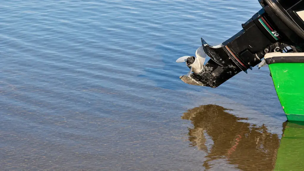
Most slipping issues are actually ventilation. Fixing engine height, adjusting trim, and selecting a cupped stainless-steel propeller will quickly restore grip and stop performance loss.
| Solution | Benefit |
|---|---|
| Repair Damaged Blades | Restores smooth water flow and improves propulsion efficiency. |
| Select Proper Pitch | Reduces blade overload and helps maintain optimal engine RPM. |
| Choose Correct Diameter | Improves thrust distribution and overall propulsion performance. |
| Adjust Engine Mounting Height | Optimizes water flow to the propeller and reduces pressure fluctuations. |
| Correct Trim Angle | Improves blade loading and enhances propulsion efficiency. |
| Clean Hull Regularly | Restores smooth water flow by eliminating marine growth and surface drag. |
| Balance the Propeller | Reduces vibration, uneven loading, and pressure imbalance. |
| Upgrade Propeller Design | Improves hydrodynamic efficiency and minimizes the risk of cavitation. |
Differentiating Ventilation from Cavitation
Operators often blame cavitation when their propeller loses grip. 실제로는, most slipping issues are actually propeller ventilation. This happens when the blades pull in surface air or exhaust gas instead of solid water. True cavitation is a hydrodynamic pressure problem where extreme low pressure forms vapor bubbles on the blade surface. It is far less common in everyday troubleshooting.
Both conditions share identical symptoms on the water. You will experience the following performance drops:
- Rising RPMs: Engine speed flares without a proportional increase in boat speed.
- Loss of thrust: The propeller suddenly drops its grip on the water.
- Slipping: Forward momentum stalls during hard acceleration or tight turns.
Optimizing Engine Height and Trim
A poorly adjusted outboard is the leading cause of poor propeller bite. Start your troubleshooting by testing the boat with the trim fully down to establish a performance baseline. Adjust the trim up slightly to find your usable running range. If the propeller still breaks loose, lower the engine mounting position on the transom. This keeps the anti-ventilation plate deeper in the water, blocking surface air from reaching the blades.
You should also trim down when entering tight turns so the propeller stays submerged as the hull leans. 마지막으로, inspect the hull ahead of the lower unit. Transducers, through-hull fittings, or debris can disrupt clean water flow and feed aerated water directly into your propeller.
Choosing a Propeller for Maximum Bite
Your propeller dictates how well your engine transfers power to the water. Always inspect the current propeller for nicks, 균열, or bent blades first. Even minor physical damage frequently causes slipping and breaks the water flow. If the blades are intact but the engine over-revs before generating forward thrust, lower the pitch to help the engine grab solid water.
You can switch to a propeller with increased cup and a larger blade area to maintain grip under heavy loads or in rough chop. Upgrading to a stiffer stainless-steel propeller prevents blade flex under load and enhances hold during aggressive maneuvers.
Utilizing Aftermarket Hardware Solutions
When height and trim adjustments fall short, aftermarket hardware can force the stern down and keep the propeller buried.
- Hydrofoils: Add a hydrofoil to the anti-ventilation plate to help lift the stern onto plane faster and reduce air ingestion.
- Transom wedges: Install a positive transom wedge to increase engine tuck and improve initial propeller bite during takeoff.
- Jack plates: Use a jack plate for precise height adjustments, ensuring the motor is not raised high enough to induce further ventilation.
Choose NEWTOP for Reliable, Precision-Built Outboard Motor Propellers
Reducing cavitation starts with choosing a propeller that is properly engineered, accurately manufactured, and matched to your application. ~에 뉴탑, we produce high-quality 선외 모터 프로펠러 for a wide range of recreational and commercial boats, combining precision machining with strict quality control to deliver stable performance on the water.
Every propeller is manufactured using carefully selected aluminum or stainless steel materials and undergoes balancing, dimensional inspection, and performance testing to ensure smooth operation, improved fuel efficiency, and longer service life. Whether you need OEM replacement propellers or customized solutions for your own brand, our engineering team can help you select the right diameter, 정점, and blade design for different engines and operating conditions.
As an experienced outboard motor propeller manufacturer and trusted outboard motor propeller factory, NEWTOP supports 글로벌 유통업체, 도매업자, and equipment brands with reliable production capacity, consistent product quality, and responsive OEM/ODM services.
Contact our team today to find the right propeller solution for your market and improve your customers’ boating performance.
자주 묻는 질문
What causes cavitation in an outboard propeller?
Cavitation occurs when water pressure on the propeller blades drops below vapor pressure, causing vapor bubbles to form and violently collapse. Damaged blades, the wrong propeller size or pitch, excessive rotational speed, or disturbed water flow from the hull and lower unit typically trigger this pressure drop.
How do I know if my boat has cavitation or ventilation?
Cavitation creates a persistent whine, harsh vibration, and visible pitting on the propeller blades, even when running straight. Ventilation happens when the prop pulls in surface air or exhaust. You will feel a sudden RPM spike and loss of bite, usually during tight turns or when you trim the motor too high.
Can cavitation damage my engine?
Cavitation destroys propeller blades through erosion rather than directly damaging the internal engine block. It does cause indirect mechanical harm. When the propeller loses its grip, the engine over-revs. These rapid load fluctuations place heavy stress on your lower unit gears, 문장, and the entire drivetrain.
Does engine height affect cavitation?
Engine height primarily drives ventilation, but it directly impacts cavitation. Mounting an outboard too high reduces propeller submergence and introduces aerated, unstable water flow. This disturbed inflow creates pressure anomalies that force vapor bubbles to form on the blades.
Will changing propeller pitch stop cavitation?
Adjusting pitch reduces cavitation only if your current propeller is over-loaded or under-loaded for your specific setup. If your engine struggles to reach its recommended wide-open throttle RPM, switching to a lower pitch helps balance the load. Pitch adjustments will not fix cavitation caused by physical blade damage, improper engine height, or hull irregularities.
Can a damaged propeller cause cavitation?
예. Nicks, 균열, bent edges, or deep scratches disrupt the smooth flow of water across the propeller blades. These physical imperfections create localized low-pressure zones that trigger vaporization. The resulting bubble collapses cause further metal erosion, driving a cycle of worsening damage.
Is cavitation worse at high speed?
As boat speed and propeller RPM increase, water velocity over the blades rises. This lowers local pressure and significantly increases your cavitation risk. While true cavitation intensifies at higher speeds, operators often notice the most dramatic symptoms—like sudden blowout and RPM flares—during heavy acceleration or tight turns due to accompanying ventilation.
Does blade material affect cavitation resistance?
Material choice dictates how well your propeller survives cavitation, not whether it occurs in the first place. High-strength copper alloys and stainless steel resist the microscopic impacts of bubble collapses far better than standard aluminum. Stronger metals also allow manufacturers to cast thinner blade profiles, which helps manage pressure distribution and delays performance loss.
