


- الجميع
- قصص عملاء نيوتوب
- نيوتوب إكسبلورر هاب
- رؤى الصناعة NEWTOP

Working with the right مورد معدات الطاقة في الهواء الطلق is only one part of an international machinery order. The same brush cutter, بالمنشار, lawn mower, generator or water pump can leave the factory with the same basic specification but face a different import process depending on whether it is headed for Nigeria, تنزانيا, Brazil or Mexico.
The trouble usually starts when compliance is checked too late. A shipment may require conformity verification before export. An electric model may fall under rules that do not apply to its gasoline-powered equivalent. Labels, technical files, or importer information may also need to change before production is completed.
للموزعين, the useful question is therefore not simply:
“Which certificate does this machine have?"
It is:
“What does this specific product need in the country where I plan to sell it?"
This guide focuses on practical import checks for major African and Latin American markets relevant to garden machinery and outdoor power equipment. It is intended to help importers know what to confirm with their supplier before an order moves into production.
Compliance note: Requirements can change and often depend on the exact HS code, product type, engine or electrical configuration, والاستخدام المقصود. Final import requirements should always be confirmed with the local importer, customs broker, conformity-assessment body, or competent authority.
Start With the Product, Not With a Certificate
There is rarely one certificate that answers every import question.
A CE document may support a technical file but does not automatically replace the local conformity route in another country. جنوب أفريقيا, for example, expressly states that CE certificates alone are not accepted for products requiring NRCS approval; accredited safety test reports are required instead.
Before asking a supplier for documents, separate the main compliance questions:
| Compliance Area | What Needs to Be Confirmed |
|---|---|
| Customs Classification | Correct HS, NCM, tariff fraction, or national tariff code |
| Product Conformity | Whether the product falls under compulsory standards or certification |
| محرك / Emission Rules | Requirements applying to gasoline or diesel engines |
| Electrical Requirements | أمان, EMC, voltage, frequency, المقابس, شواحن, or electrical components |
| Labeling | Language, importer details, معلومات السلامة, التقييمات, and local markings |
| Pre-Shipment Verification | Whether conformity needs to be checked before export |
| Import Documents | Invoice, packing list, certificate of origin, bill of lading, تقارير الاختبار, and permits |
The correct order is usually:
identify the product → confirm the tariff classification → check the applicable regulation → prepare the required product and shipment documents.
Starting with “we already have CE” and trying to work backwards is far less reliable.
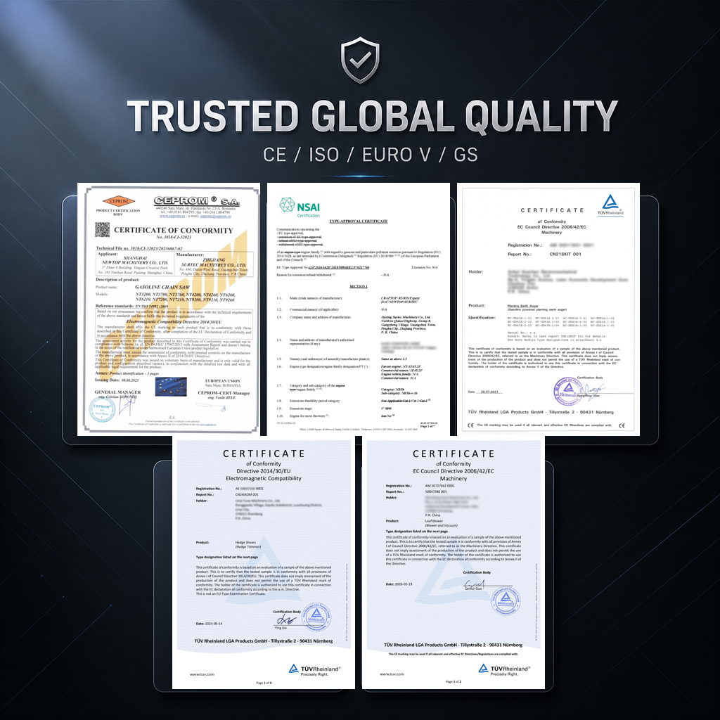
Importing Garden Machinery into Africa
Africa is not one regulatory market. Nigeria, كينيا, تنزانيا, زامبيا, Ghana and South Africa all approach imported equipment differently.
For Chinese exporters in particular, Kenya and Tanzania also deserve early attention because conformity work may take place before the goods leave China.
Nigeria: SONCAP Needs to Be Checked Early
Nigeria’s SONCAP system applies to SON-regulated imported products and operates as an offshore, pre-shipment conformity-assessment programme.
For regulated goods, the process can involve a Product Certificate, testing and verification in the exporting country, a Certificate of Conformity, and ultimately the SONCAP Certificate used for customs clearance. SON states that Product Certificates are used in the Form M process, while the SONCAP Certificate is required for customs clearance of regulated goods.
That makes Nigeria a poor market for leaving compliance until the container is ready.
Before confirming a commercial order, the importer should establish:
- whether the actual product is within SONCAP scope;
- which applicable standard and certification route will be used;
- what documents the exporter needs to prepare;
- whether inspection or testing will be required before shipment.
أ موزع importing finished chainsaws, قواطع الفرشاة, مولدات, or other machinery for resale should also avoid assuming that an exemption intended for industrial machinery imported for a manufacturer’s own use applies to normal commercial stock.
The exact product and intended import route matter.
Ghana: Mandatory Standards and EasyPASS Are Not the Same Thing
Ghana is worth treating carefully because EasyPASS attracted considerable attention in 2026.
In July 2026, the Ghana Standards Authority clarified that EasyPASS did not introduce a new compulsory requirement for every importer. It is an established conformity-assessment programme. في نفس الوقت, GSA emphasized that products placed on the Ghanaian market must still comply with applicable mandatory Ghana Standards, regardless of whether the business participates in EasyPASS.
So the first question should not be “Do I need EasyPASS?"
It should be:
Is this particular machine covered by a mandatory Ghana Standard, and what conformity route applies to it?
For customs clearance, Ghana Revenue Authority currently lists documents such as the Bill of Lading or waybill, invoice, packing list, Import Declaration Form, importer identification, and any permit required by the relevant regulator.
For the exporter, consistency matters. The model description on the invoice, packing list, technical documents, labels and physical machine should tell the same story.
كينيا: PVoC Can Put the Inspection Before the Shipment
Kenya operates a Pre-Export Verification of Conformity programme through KEBS.
The current KEBS guidance states that PVoC is carried out in the exporting country to verify compliance with applicable Kenyan technical regulations, mandatory standards, or approved specifications. China is included among the exporting zones served by KEBS-appointed PVoC contractors.
For an outdoor equipment order, that can move part of the compliance work forward in the purchasing timeline.
Instead of waiting for cargo to arrive in Kenya, the importer and supplier may need to coordinate product information, supporting test reports, physical inspection, and certification while the goods are still in the country of export.
A practical sequence is:
Product scope → applicable Kenyan standard → PVoC request → inspection/testing if required → CoC → shipment
Not every import uses the same route, and KEBS publishes exemptions for certain goods and users. A commercial distributor should therefore confirm the actual treatment rather than assume an exemption applies.
تنزانيا: For Regulated Goods, the CoC Is Part of the Shipping Plan
Tanzania also operates a PVoC system, and the current TBS programme covers regulated products before export.
TBS’s 2025 PVoC guideline states that affected consignments are inspected and/or tested before shipment and require a Certificate of Conformity. Its current import-control page also maintains lists of regulated HS codes and PVoC procedures.
This is particularly relevant to NEWTOP because TBS issued a June 2026 notice specifically reminding importers of regulated goods originating from China Mainland and several nearby territories that PVoC inspection must take place in the country of export before shipment.
For a Tanzanian buyer, the supplier therefore needs more than a generic PDF test report. The important issue is whether the product information and available conformity evidence are suitable for the actual TBS route.
TBS’s summarized procedure indicates that documentary review can include technical product details, third-party conformity evidence, accredited laboratory reports, and control testing where necessary.
زامبيا: Check Whether the Product Is Actually Under a Compulsory Standard
Zambia takes a more product-specific approach.
The Zambia Compulsory Standards Agency currently administers import quality monitoring for goods covered by compulsory standards. Its published information states that the system applies specifically to regulated products rather than every imported item.
This distinction is useful for garden machinery.
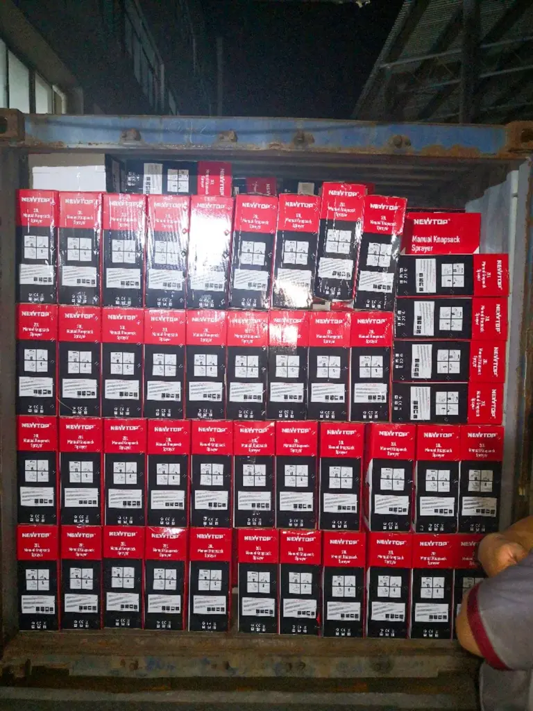
A gasoline machine, an electrical tool, a battery-related product, and an accessory should not automatically be treated as one compliance category.
Before asking a supplier to obtain a particular certificate, the importer should first compare the product against the current ZCSA compulsory-standard scope.
ZCSA also provides several import-clearance arrangements, including batch clearance, pre-import schemes, and annual import quality certification for qualifying importers.
بعبارة أخرى, the compliance conversation becomes more efficient when the buyer starts with the exact product rather than a generic request for “Zambia certification.”
جنوب أفريقيا: Battery-Powered Garden Equipment Deserves a Separate Check
South Africa is one of the markets where gasoline-powered and battery-powered garden equipment should not automatically be treated under the same compliance route.
The NRCS regulates certain electrical and electronic products under compulsory specifications. Its current list includes VC 9105 for electric motor-operated hand-held tools, transportable tools, and lawn and garden machinery. Battery-powered garden equipment may therefore require a separate regulatory check even though the machine itself is not connected directly to mains power.
Where a product falls within the applicable compulsory specification, the relevant model or product family may require regulatory approval before entering the South African market. The applicant must be a South African legal entity, and accredited test reports can form part of the approval evidence.
The charger should also be reviewed separately, as its rated voltage, plug configuration, electrical safety, and other requirements may fall under additional South African electrical regulations.
NRCS is also clear on one point:
A CE certificate on its own is not accepted as the regulatory approval basis.
This does not mean gasoline-powered chainsaws, الرشاشات, or brush cutters automatically follow the same approval route.
For distributors carrying both gasoline and lithium battery-powered outdoor equipment, each product type should be checked against the applicable NRCS scope rather than using one compliance file across the entire range.
Importing Garden Machinery into Latin America
Latin America often looks different from the African PVoC markets.
Rather than one broad pre-export programme, compliance frequently begins with the tariff classification and then moves into product-specific technical regulations, electrical requirements, labeling, or import authorizations.
That makes the exact product description particularly important.
البرازيل: Start With the NCM, Not With “Do You Have Inmetro?"
Brazilian importers should begin with the NCM classification.
Inmetro’s latest guidance, updated in August 2026, tells importers to use the NCM code in Portal Único Siscomex to check the applicable administrative treatment and determine whether Inmetro approval is required.
This matters because an NCM falling within a controlled area does not automatically mean every product classified there follows the same certification requirement. Inmetro also provides exclusions and exemption routes where the specific product falls outside regulatory scope.
ابدأ بـ: Correct NCM classification
Check next: Administrative treatment in Portal Único Siscomex
If applicable: Confirm whether Inmetro certification, registration, or import approval is required
Prepare before ordering: Exact model, technical description, power source, voltage/frequency where applicable, manufacturer details, and supporting test documentation
For the supplier, this means the final model information cannot be vague.
Inmetro’s import guidance specifically calls for clear product descriptions containing information such as brand, model or part number, technical characteristics, قوة, voltage, نطاق التشغيل, and application where relevant.
A gasoline lawn mower, an electric pressure washer, and a battery charger may therefore follow different compliance routes even though one distributor buys all three from the same factory.
المكسيك: Match the Tariff Fraction to the Applicable NOM
Mexico also works better when the importer begins with classification rather than with a certificate name.
SNICE maintains an Annex of tariff fractions subject to compliance with Mexican Official Standards at import. The applicable NOM therefore needs to be checked against the actual tariff fraction and product scope.
For an importer, the workflow is more useful when expressed this way:
Tariff fraction → Applicable NOM → Conformity / labeling requirements → Final Spanish product information and packaging
Electrical equipment needs particular care because electrical-safety requirements may involve different standards from gasoline-powered equipment.
The importer should therefore finalize the correct model, التكوين الكهربائي, التقييمات, and labeling requirements before artwork and packaging are approved.
It is much easier to print the right Spanish label at the factory than to correct thousands of boxes after customs or market-surveillance questions arise.
كولومبيا: Check the Technical Regulation Before Commercialization
Colombia applies technical regulations by product rather than by the broad description “garden machinery.”
The Superintendencia de Industria y Comercio states that products subject to technical regulations must comply with the applicable regulation before commercialization and may require the appropriate conformity certificate. Manufacturers and importers of goods covered by SIC-supervised technical regulations are also subject to registration requirements.
Electrical products require another layer of attention.
Colombia updated its RETIE framework through Resolution 40284 of June 23, 2026. The current regulation contains separate sections dealing with products within scope and conformity assessment.
That does not mean every electric lawn mower or charger automatically falls under RETIE in the same way.
The importer needs to check the exact product against the current scope.
For mixed petrol and electric ranges, one regulatory answer should therefore never be copied across every SKU without verification.
شيلي: Check SEC Scope for Electrical and Fuel-Related Products
Chile operates compulsory certification systems through the Superintendencia de Electricidad y Combustibles for specified electrical and fuel products.
SEC states that products falling within the mandatory system must be certified before commercialization and carry the applicable certification marking. It also provides different conformity routes, including mechanisms involving recognized foreign certification in eligible cases.
For a garden-machinery importer, the first job is to confirm whether the exact product appears within SEC’s regulated scope.
If it does, certification, testing, labels, and supporting product information should be planned before shipment.
If it does not, the importer should not request a random “SEC certificate” simply because another electrical product needed one.
The scope of the regulation remains the deciding factor.
بيرو: Use the Tariff Subheading to Find the Restriction
Peru makes this process fairly easy to understand conceptually.
SUNAT advises importers to use the national tariff subheading to identify whether goods are subject to restrictions and which government authority issues the relevant control document. Restricted goods require the appropriate authorization in addition to normal customs documents.
For many regulated procedures, Peru’s VUCE acts as the electronic trade window.
So instead of starting with assumptions based on another Latin American country, the buyer can work through:
Peruvian tariff subheading → restriction check → competent authority → required document
This is particularly useful when a distributor carries several equipment categories.
A gasoline engine product, electric machine, accessory, or battery-related product may not all produce the same result.
فنزويلا: Verify the Current Tariff Treatment Before Production Is Finished
Venezuela deserves more caution because its customs tariff has undergone repeated amendments, including further changes during 2026. Current tariff treatment should therefore be checked against the exact product code at the time of the import.
Under the Venezuelan customs framework, Legal Regime 20 is linked to goods affected by mandatory COVENIN standards or technical regulations, with SENCAMER involved in determining applicability. لكن, this should not be interpreted as meaning every chainsaw, mower, قطع الفرشاة, مولد, or pump automatically follows that procedure.
Do not assume that every garden machine follows the same SENCAMER procedure. The local importer or customs representative should verify the current tariff code, applicable legal regime, and any COVENIN or technical-regulation requirement before labels, التعبئة والتغليف, and shipment are finalized.
This is especially important where customized labels or importer information are involved.
The local check should happen before the supplier finishes artwork and production—not after the goods are already on the water.
Gasoline and Battery-Powered Equipment Need Different Compliance Checks
Product type can change the regulatory discussion even within the same country.
For conventional gasoline-powered equipment, the buyer may need to consider engine specifications, emissions documentation, معلومات السلامة, noise requirements, and fuel-system characteristics where relevant.
NEWTOP also offers lithium battery-powered outdoor equipment. These products should be reviewed separately because lithium batteries can introduce additional safety, مواصلات, testing, documentation, and destination-market requirements. The charger may also bring its own electrical requirements, including rated voltage, frequency, plug configuration, electrical safety, and EMC, depending on the market.
لهذا السبب, a compliance file confirmed for a gasoline brush cutter should never be assumed to cover a lithium battery-powered model simply because the two products serve the same application.
What the Outdoor Power Equipment Supplier Can Prepare
The local importer remains responsible for confirming the final regulatory route, but the supplier plays an important role long before the customs declaration is filed.
When a buyer provides clear destination-market requirements, NEWTOP can review the product configuration and prepare supporting information before the order is finalized.
Typical export documents available can include:
- Commercial Invoice
- Packing List
- Certificate of Origin
- Bill of Lading
- Product manuals
- Test reports
- Other agreed product or shipment documentation
Depending on the product and model, NEWTOP also has documentation or certifications مشتمل م, EMC, وكالة حماية البيئة, RoHS and EURO V. Marine products can involve additional certification such as احتجاز ثاني أكسيد الكربون.
These should not be presented as a single certificate package covering every NEWTOP product.
The right approach is to match the available document to the actual model, وجهة, and import requirement.
Labels and Packaging Can Be Prepared for the Market
A supplier can also prevent problems by getting market-specific product information right during production.
Voltage and frequency must always reflect the machine’s actual technical configuration. They should not be altered simply because a customer requests different numbers on the label.
Other elements can be customized according to confirmed importer requirements, مشتمل:
- language;
- importer information;
- warning labels;
- product and carton labels;
- logos;
- packaging artwork;
- barcodes and other commercial information.
For NEWTOP distributors and appointed agents, these market-specific requirements can be discussed before production so that the finished goods arrive with the agreed branding and information already in place.
That is considerably more efficient than relabeling inventory after it reaches the destination.
A Pre-Shipment Compliance Review Saves More Than a Port-Side Fix
Before production is released or the container is booked, the importer and supplier should make sure they are working from the same final compliance information.
The useful questions are straightforward:
- What is the final HS, NCM, or national tariff code?
- Is the product covered by a compulsory technical regulation?
- Does it require PVoC, certification, registration, or another approval?
- Is the final engine or electrical configuration the same one used in the technical documents?
- Are voltage and frequency correct?
- Has the required label language been confirmed?
- Does the market require importer information on the product or package?
- Which test reports or certificates are available for the actual model?
- Do the invoice and packing-list descriptions match the goods?
- Is a Certificate of Origin required?
- Does a lithium product need a separate compliance and transport review?
For mixed containers, this check becomes even more important. One shipment may include gasoline machinery, electric tools, قطع غيار, and battery products, yet each group can follow a different regulatory path.
Compliance Is Easier to Fix Before Production Than After Arrival
There is no single “Africa certificate” or “Latin America certificate” for garden machinery.
Nigeria may require SONCAP for regulated commercial goods. Kenya and Tanzania can move conformity verification into the exporting country. Zambia works from its compulsory-standard scope. South Africa has specific requirements for regulated electrical lawn and garden machinery.
Across Latin America, البرازيل, المكسيك, بيرو, and other markets often make the tariff classification the starting point for determining what comes next.
That is where cooperation with an experienced outdoor power equipment supplier matters.
NEWTOP can support importers with product specifications, available certification and test documentation, export documents, and customized labels or packaging according to confirmed market requirements. Complete machines and spare parts can also be coordinated within the same sourcing process.
But the safest sequence should stay the same:
Identify the exact product. Confirm the destination requirement. Finalize the specification and labeling. Prepare the documents. Then ship.
Most compliance problems cost far less to solve while the machine is still on a production sheet than when the container is already waiting at the destination port.
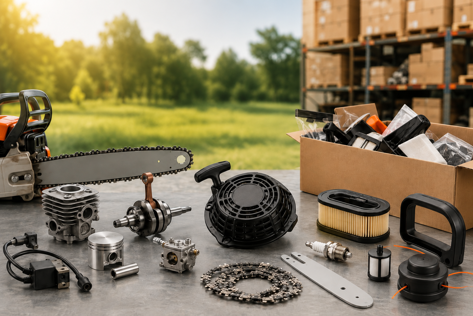
يصبح الحصول على قطع غيار وملحقات معدات الطاقة الخارجية أمرًا معقدًا قبل فترة طويلة من تزايد الطلب. قد يتعامل الموزع مع عدد قليل فقط من عائلات الآلات, ومع ذلك، فإن أجزاء الخدمة الموجودة خلفها يمكن أن تصل إلى عشرات أو مئات من وحدات SKU. تصل بعض العناصر بأرقام أجزاء واضحة. والبعض الآخر يأتي كصور ورشة عمل, العينات القديمة, أو أوصاف مثل "بداية لهذا النموذج".
التحدي لا يتمثل في مجرد العثور على مصنع يبيع المكربنات, مبتدئين الارتداد, ملفات الإشعال, اسطوانات, بيستونز, أعمدة الكرنك, أو علب التروس. الجزء الأصعب هو إبقاء كل مكون مرتبطًا بالجهاز الصحيح, التحكم في أوامر SKU المختلطة, والتأكد من إمكانية تحديد نفس الجزء مرة أخرى عندما يحتاج المخزون إلى التجديد.
للتجار والموزعين, جيد مورد قطع الغيار ينبغي أن يجعل هذه العملية أسهل، وليس إضافة طبقة أخرى من عدم اليقين.
طلب قطع الغيار ليس مجرد طلب طويل للآلة
الآلات الكاملة سهلة التحديد نسبيًا. يؤكد المشتري النموذج, كمية, إعدادات, التعبئة والتغليف, والوجهة.
أوامر قطع الغيار تتصرف بشكل مختلف.
قد يحتوي على استفسار واحد 40 أو 50 خطوط منفصلة. وقد يجمع جهاز آخر مكونات من عدة عائلات آلية, وبكميات مختلفة لكل صنف. بعض الأجزاء تتحرك بسرعة في السوق المحلية, بينما لا تكون هناك حاجة إلى البعض الآخر إلا في بعض الأحيان لإصلاحات الورشة.
يؤدي هذا إلى إنشاء عبء عمل شراء مختلف. يجب على الموزع إدارة التوافق, تحديد SKU, مراجع التعبئة والتغليف, كميات, ومعلومات إعادة الطلب المستقبلية في نفس الوقت.
يكون عرض الأسعار الرخيص ذا قيمة محدودة إذا تبين أن عدة مكونات غير صحيحة بمجرد وصول الشحنة إلى ورشة العمل.
ابدأ بالآلة, ليس فقط اسم الجزء
"المكربن,"" ملف الإشعال,"أو "بادئ الارتداد" نادرًا ما تكون معلومات كافية للمطابقة الموثوقة.
يجب أن يبدأ الاستفسار المفيد بالجهاز نفسه. كلما كان ذلك ممكنا, يمد:
- طراز الآلة أو المحرك
- رقم الجزء الموجود, إذا كان متاحا
- صور واضحة للمكون الأصلي
- الكمية المطلوبة
- الأبعاد الرئيسية عندما تكون المباراة غير مؤكدة
- علامات مرئية, الموصلات, الخطوط, المواضيع, أو نقاط التثبيت
تصبح الصور مفيدة بشكل خاص عندما لا تكون العبوة الأصلية أو الوثائق متوفرة. للآلات القديمة, غالبًا ما توفر الصورة الواضحة للجزء ومنطقة التركيب الخاصة به معلومات أكثر فائدة من الوصف العام.
مثال حقيقي للمصادر
اتصل بائع تجزئة للمعدات الزراعية التنزاني ذات مرة بشركة NEWTOP وطلب منها العشرات من أجزاء رشاشات PJH المختلفة. كانت كمية كل قطعة صغيرة نسبيًا - أقل من 1,000 قطع لكل SKU - والعديد من المكونات لم تكن عناصر يتم إنتاجها بشكل شائع بكميات كبيرة.
تمت معالجة الطلب من خلال مطابقة مراجع جهاز العميل وصور المنتج بدلاً من التعامل مع كل سطر كجزء غير ذي صلة. في غضون يومين, تم تحديد العناصر المطلوبة وتنظيمها لعرض الأسعار.
لم يكن الجزء الصعب مكونًا واحدًا غير عادي. لقد كانت تحتفظ بقائمة طويلة من المتطلبات الصغيرة المطابقة بشكل صحيح للآلات التي تنتمي إليها.
هذا النوع من الاستفسار أقرب بكثير إلى طلب قطع غيار موزع حقيقي من شرائها 5,000 قطع متطابقة.
التوافق يأتي قبل السعر
يمكن أن يبدو المكونان متطابقين تقريبًا ولكنهما يختلفان في المكان المهم.
قد يستخدم بادئ الارتداد نمطًا مختلفًا لفتحة التثبيت. قد يحتوي ملف الإشعال على موصل أو موضع تثبيت مختلف. يمكن أن تختلف أعمدة الكرنك في أبعاد العمود أو تفاصيل الخيط. اسطوانات, قد تحتوي المكابس وعلب التروس على اختلافات في الإصدار يصعب التعرف عليها من صورة الكتالوج وحدها.
اعتمادا على الجزء, قد يتضمن التأكيد التحقق من مواضع التثبيت, أبعاد, أقطار رمح, المواضيع, الخطوط, الموصلات, أسطح مانعة للتسرب أو تفاصيل أخرى خاصة بالطراز.
وينطبق هذا أيضًا على الأجزاء الموصوفة بأنها بدائل مباشرة. يجب تأكيد الإعداد وفقًا لطراز الماكينة ذات الصلة والمعلومات المرجعية المتاحة قبل الانتهاء من الطلب بالجملة.
في نيوتوب, يمكن مطابقة الأجزاء وفقًا لطراز الجهاز الخاص بالعميل, صور, والمتطلبات المؤكدة. يمكن للمشترين بعد ذلك الاختيار بين مجموعة الأجزاء المطابقة الكاملة والمكونات الفردية, تخضع لموك المعمول بها.
مجموعة أجزاء كاملة أو أجزاء فردية?
يعتمد الخيار الأفضل على كيفية بيع الوكيل للمعدات وصيانتها.
| تنسيق الشراء | أكثر ملاءمة ل | الفائدة الرئيسية |
|---|---|---|
| مجموعة أجزاء كاملة | يقوم التجار ببناء تغطية الخدمة حول منصة آلة واحدة | تغطية أوسع للأجزاء في عملية شراء واحدة |
| الأجزاء الفردية | التجار الذين لديهم بيانات الإصلاح أو المبيعات الحالية | قم بتجديد وحدات SKU المطلوبة حاليًا فقط |
يمكن أن تكون المجموعة الكاملة مفيدة عندما يدخل الموزع في فئة ماكينات جديدة أو يريد نطاق إصلاح أوسع متاحًا من البداية.
تصبح المكونات الفردية أكثر منطقية بمجرد أن يوضح السوق المحلي الأجزاء التي يتم تشغيلها بشكل أسرع. يمكن للتاجر بعد ذلك تجديد المكربنات, مبتدئين الارتداد, ملفات الإشعال, اسطوانات, بيستونز, أعمدة الكرنك, علب التروس, أو غيرها من العناصر المطلوبة بشكل متكرر بشكل منفصل.
في الممارسة العملية, يستخدم العديد من الموزعين كليهما. تتلقى عائلات الماكينات الأساسية تغطية أوسع للأجزاء, في حين يتم إعادة ترتيب وحدات SKU سريعة الحركة بشكل فردي.
إدارة أجزاء وملحقات معدات الطاقة الخارجية عبر وحدات SKU المتعددة
لا يبدو طلب ما بعد البيع النموذجي دائمًا مثيرًا للإعجاب على الورق.
قد تشمل 30 قطع من مكون واحد, 60 من آخر, عدة عشرات من العنصر الثالث, وآخر 20 أو 30 SKU بكميات أقل. بمجرد مشاركة فئات الآلة المتعددة, عدد الخطوط ينمو بسرعة.
هذا هو المكان الذي يصبح فيه التوريد الشامل أكثر فائدة من مجرد الحصول على كتالوج منتجات طويل.
يمكن لـ NEWTOP دعم شراء SKU المختلط عبر العشرات أو حتى المئات من عناصر قطع الغيار, بشرط استيفاء موك للمنتجات ذات الصلة. دفعة صغيرة, يمكن التعامل مع متطلبات SKU المتعددة ضمن مشروع المصادر نفسه.
اعتمادا على الاستفسار, يمكن أن يشمل الطلب:
- الأجزاء التي تم تحديدها من نماذج الآلة
- المكونات مطابقة من صور العملاء
- مجموعات الأجزاء المطابقة الكاملة
- قطع غيار فردية
- آلات كاملة مع قطع الغيار المقابلة
- تغليف OEM
- أرقام الأجزاء الخاصة بالعميل
- تسميات الباركود
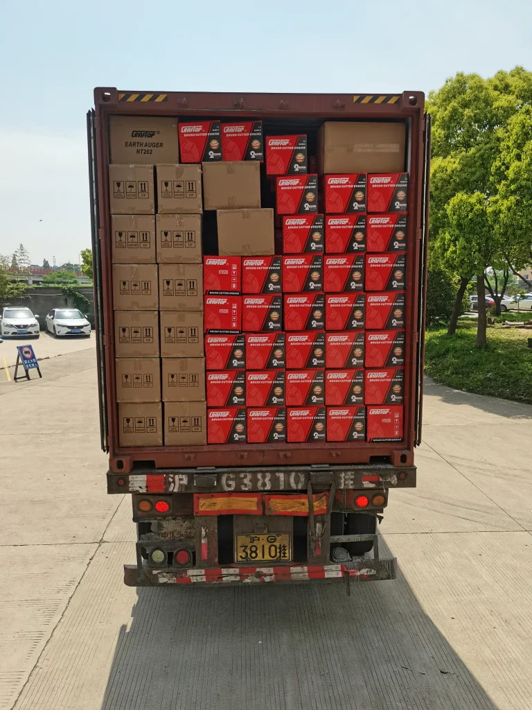
لموزع شراء الآلات بالفعل, إضافة أجزاء الخدمة ذات الصلة إلى نفس خطة الشراء يمكن أيضًا أن يقلل من أعمال التنسيق. لا تحتاج الآلات وقطع الغيار إلى التحرك عبر سلاسل توريد منفصلة تمامًا.
الأمر نفسه ينطبق على مراجع التعبئة والتغليف والمخزون. إذا كان المشتري يستخدم بالفعل أرقام الأجزاء الداخلية أو الرموز الشريطية, يمكن دمج هذه المعرفات في عبوات OEM بعد تأكيد التفاصيل.
يصبح هذا ذا أهمية متزايدة مع توسع الكتالوج.
إن توفير بضعة سنتات على مكون واحد قد لا يعني الكثير إذا كان على فريق الشراء التنسيق بين عشرة موردين مختلفين, التوفيق بين العديد من أنظمة الترقيم, أو إعادة تحديد الأجزاء في كل مرة تحتاج فيها ورشة العمل إلى مخزون.
للشركات التي تشتري قطع غيار وملحقات معدات الطاقة الخارجية بانتظام, يجب قياس الكفاءة عبر النظام الكامل, ليس فقط على مستوى SKU.
كيف يتم فحص جودة الأجزاء قبل الشحن
لا ينبغي أن يتوقف فحص الأجزاء عند المظهر.
المكونات المختلفة لها مخاطر فشل مختلفة. قد تكون دقة الأبعاد حاسمة بالنسبة لعنصر واحد, بينما صلابة, التوازن الدوراني, أداء الختم, أو قد يكون تكوين المواد أكثر أهمية بالنسبة لشخص آخر.
تستخدم NEWTOP معدات فحص احترافية للمكونات الواردة, مع طريقة الفحص المختارة وفقًا للجزء ومتطلبات الجودة ذات الصلة.
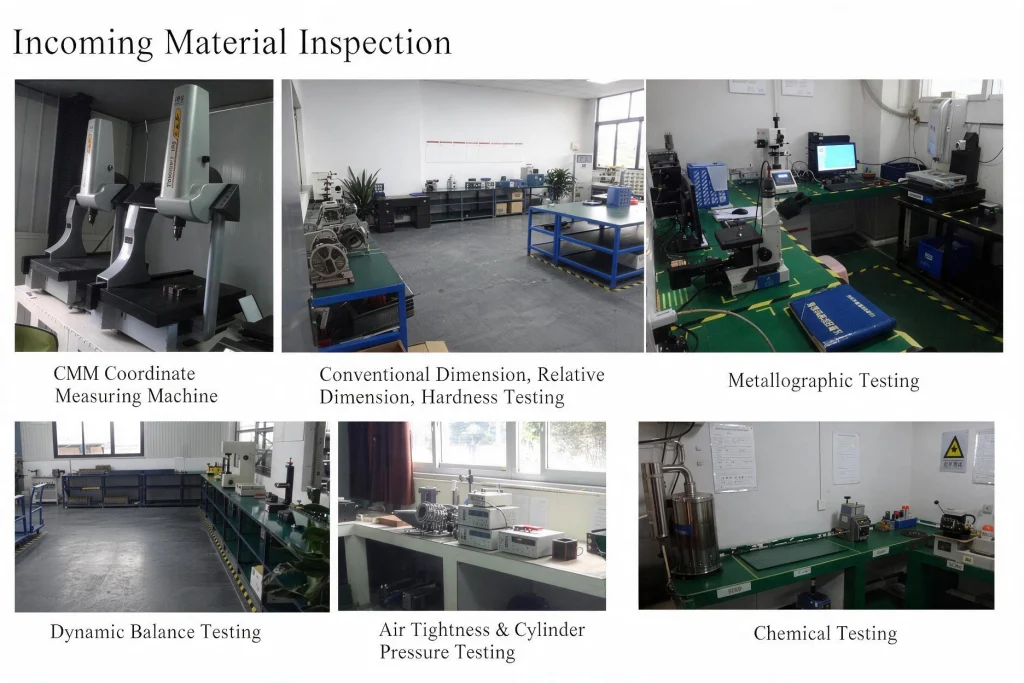
وتشمل طرق التفتيش المتاحة:
| منطقة التفتيش | فحص نموذجي |
|---|---|
| أبعاد | الأبعاد التقليدية, الأبعاد النسبية, وقياس CMM |
| مادة | صلابة, علم المعادن, والاختبارات الكيميائية |
| المكونات الدوارة | اختبار التوازن الديناميكي |
| الأجزاء المتعلقة بالأسطوانة | اختبار ضيق الهواء وضغط الاسطوانة |
آلة قياس الإحداثيات, أو سم, يمكن استخدامها حيث يلزم التحقق من العلاقات الأبعاد أو الموضعية الأكثر دقة.
يرتبط اختبار التوازن الديناميكي بالمكونات الدوارة حيث قد يساهم عدم التوازن في الاهتزاز أو التشغيل غير المستقر.
للمكونات المتعلقة بالاسطوانة, يمكن تطبيق اختبار ضيق الهواء وضغط الأسطوانة حيث يلزم التحقق من أداء الختم. تتوفر الاختبارات المعدنية والكيميائية عندما يتطلب هيكل المادة أو تركيبها مزيدًا من الفحص.
ليس كل مكون يمر عبر كل اختبار. يجب أن يتطابق التفتيش مع الجزء ومخاطر الجودة الخاصة به.
وهذا التمييز مفيد عند المقارنة بين الموردين. عادةً ما يخبر السؤال عن كيفية فحص جزء معين المشتري أكثر من السؤال عما إذا كان "فحص الجودة" متاحًا أم لا.
اجعل الطلب الأول أسهل في إعادة الطلب
الاقتباس الأول يحظى بأكبر قدر من الاهتمام, لكن الاختبار الحقيقي لنظام توريد قطع الغيار غالباً ما يأتي بعد أشهر.
ورشة عمل تطلب نفس المبدئ مرة أخرى. يحتوي المستودع على رمز منتج لا يتعرف عليه المورد. الاقتباس السابق يقول فقط "تجميع البداية". يتعين على شخص ما بعد ذلك العثور على صورة قديمة وبدء عملية المطابقة مرة أخرى.
وهذا أمر يمكن تجنبه.
احتفظ بالمرجع, ليس فقط اسم الجزء
بمجرد تأكيد الجزء, فهو يساعد على الاحتفاظ بسجل بسيط:
- رقم جزء المورد
- رقم جزء العميل
- نموذج الآلة
- الإعداد المؤكد
- صورة المنتج
- الباركود
- مرجع التغليف
- كمية الطلب السابقة
إذا كان الموزع يستخدم بالفعل نظام تخطيط موارد المؤسسات (ERP)., كتالوج, أو نظام ترميز المستودعات, يمكن أن تظهر مراجعها الخاصة أيضًا على ملصقات OEM والتغليف.
الفائدة بسيطة: شراء, مستودع, مبيعات, ويمكن لفرق الخدمة الرجوع إلى نفس العنصر بنفس الطريقة.
يصبح الأمر أكثر فائدة عندما يتم الحصول على الآلات وقطع الغيار من خلال نفس المنصة. يمكن ربط المعدات التي تم بيعها بالفعل في السوق بأجزاء الخدمة المطلوبة لاحقًا, ويمكن أن تشمل شحنات الماكينات المستقبلية العناصر البديلة التي تستهلكها ورش العمل فعليًا.
يجب أن يبدو الأمر الثاني المنظم جيدًا أقل تشابهًا:
"هل يمكنك تحديد هذا الجزء?"
وأكثر مثل:
"يرجى تجديد وحدات SKU المؤكدة هذه."
هذه عملية توريد ما بعد البيع أكثر صحة.
ما يجب إرساله عند طلب عرض أسعار لقطع الغيار
ليس من الضروري أن يكون طلب عرض الأسعار الجيد لقطع الغيار معقدًا. إنها ببساطة تحتاج إلى معلومات كافية حتى يتمكن المورد من تحديد كل عنصر بشكل صحيح.
قائمة مرجعية عملية لطلب عرض الأسعار (RFQ).
يحضر:
- طراز الآلة أو المحرك
- اسم الجزء ورقم الجزء, إذا كان متاحا
- صور واضحة للجزء الأصلي
- الكمية المطلوبة لكل SKU
- الأبعاد أو العينة المادية إذا كان الإعداد غير مؤكد
- متطلبات المجموعة الكاملة أو الأجزاء الفردية
- تغليف OEM, الباركود, أو متطلبات رقم جزء العميل
- بلد المقصد ومتطلبات الشحن
للاستفسار الذي يحتوي على العديد من وحدات SKU, عادةً ما تكون إدارة جدول بيانات يحتوي على عنصر واحد في كل صف أسهل بكثير من إدارة عشرات الرسائل والصور المنفصلة.
إذا لم يكن من الممكن تحديد المكون بثقة, فمن الأفضل ترك الأمر معلقًا للتأكيد بدلاً من فرض المطابقة لمجرد إكمال عرض الأسعار.
يجب أيضًا أن يصبح الحصول على قطع الغيار الجيدة أسهل مع كل عملية إعادة طلب. مرة واحدة نموذج الجهاز, الإعداد, رقم الجزء, التعبئة والتغليف, وتم تسجيل مرجع المشتري, لا ينبغي تحديد نفس المكون من البداية في كل مرة ينخفض فيها المخزون.
للتجار والموزعين, وبالتالي فإن المورد الموثوق لقطع غيار وملحقات معدات الطاقة الخارجية ليس مجرد شركة ذات كتالوج كبير. الشريك الأقوى هو الذي يمكنه التعامل مع وحدات SKU المختلطة, تأكيد التوافق, دعم فحص الجودة المناسب, والحفاظ على تنظيم التجديد في المستقبل.
تجمع NEWTOP بين الآلات الكاملة وقطع الغيار ضمن منصة مصادر واحدة. يمكن للمشترين الحصول على مجموعات الأجزاء المطابقة الكاملة, المكونات الفردية, أو الآلات وقطع الخدمة معًا وفقًا لمتطلبات السوق وموك.
قد لا يزال ترتيب الأجزاء الأولى يتطلب مطابقة دقيقة. الجزء المهم هو التأكد من الثاني, ثالث, والأوامر الرابعة تصبح أسهل.
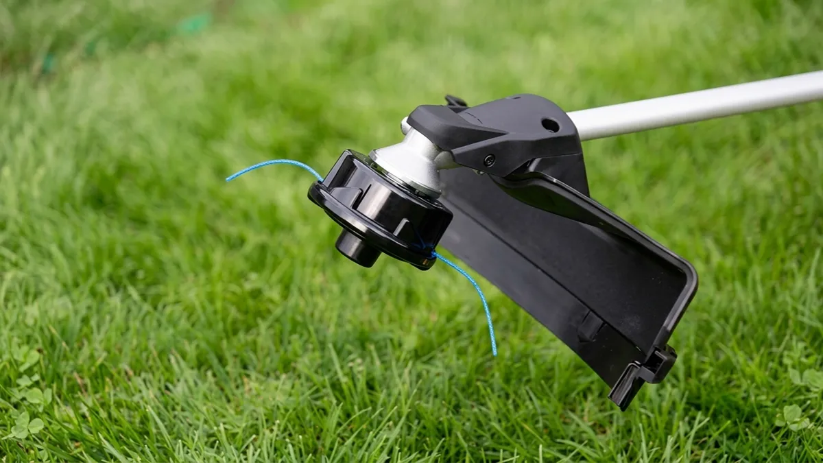
يمكن أن يؤثر اختيار رأس تشذيب السلسلة المناسب على أداء القطع, استهلاك الخط, تحميل الآلة, وكفاءة المشغل. قد لا يكون الرأس المصمم لتقليم العشب الخفيف مناسبًا للأعشاب الكثيفة أو الفرشاة, في حين أن نظام الشفرة للخدمة الشاقة قد يكون غير ضروري لحواف العشب البسيطة.
على نطاق واسع, يمكن تصنيف رؤوس تشذيب الخيوط بعدة طرق, بما في ذلك آلية التغذية, طريقة تحميل الخط, وسط القطع, تكوين منفذ الخط, وتصميم الشفرة. يساعد فهم هذه الاختلافات المستخدمين على تحديد نظام القطع الذي يتوافق مع الماكينة والمهمة.
يشرح هذا الدليل الأنواع الرئيسية لرؤوس التشذيب, كيف يعملون, ما هي التطبيقات التي تناسبهم, وكيفية التحقق من التوافق قبل استبدال واحد.
ما هو رأس تشذيب السلسلة?
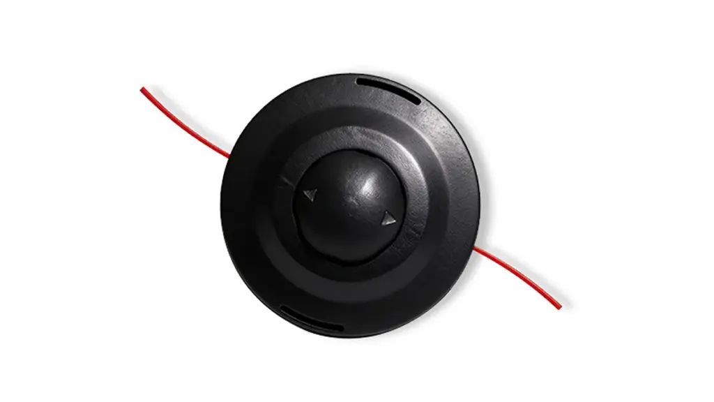
أ رأس تشذيب السلسلة هي مجموعة القطع المثبتة في الجزء السفلي من أداة تشذيب السلسلة أو عمود قطع الفرشاة. إنه يحمل خط القطع ويتحكم في كيفية تحرير الخط أثناء دوران الرأس. عندما يقوم المحرك أو المحرك بتشغيل العمود, يدور رأس أداة التشذيب بسرعة عالية, مما يتسبب في امتداد خط النايلون إلى الخارج وقطع العشب, الأعشاب, وغيرها من النباتات الخفيفة.
المكونات الرئيسية لرأس تشذيب السلسلة
يتكون رأس تشذيب السلسلة النموذجي من عدة مكونات رئيسية. يعتمد الهيكل الدقيق على نوع الرأس, ولكن الأجزاء الرئيسية تشمل عادة:
- السكن: يحمي الجسم الخارجي المكونات الداخلية ويثبت نظام القطع معًا.
- التخزين المؤقت: تستخدم في الرؤوس من نوع البكرة لتخزين خط النايلون المجروح.
- خط الانتهازي: مادة قطع النايلون التي تتصل وتقطع العشب والأعشاب الضارة.
- آلية التغذية: يتحكم في كيفية تحرير الخط الإضافي. تستخدم رؤوس التغذية النتوءية آلية الارتطام, بينما تستخدم تصميمات التغذية التلقائية نظام إصدار داخلي.
- مقبض عثرة: تم العثور عليها على العديد من رؤوس التغذية النتوءية. يسمح للمشغل بإطلاق المزيد من الخطوط عن طريق النقر برأسه على الأرض.
- غطاء أو كاب: يحمل البكرة والأجزاء الداخلية في مكانها ويسمح بالوصول لاستبدال الخط.
- تركيب الجوز أو المحول: يربط رأس أداة التشذيب بعمود محرك الماكينة. يجب أن يتطابق الخيط ونظام التثبيت مع أداة التشذيب.
- الثقوب أو فتحات الخط: قم بتوجيه خط النايلون من داخل الرأس إلى الخارج أثناء التشغيل.
كيف يتم تصنيف رؤوس تشذيب الخيوط?
يمكن تصنيف رؤوس التشذيب الخيطية من عدة زوايا مختلفة لأن الرأس الواحد يمكن أن ينتمي إلى أكثر من فئة في نفس الوقت.
طرق التصنيف الأكثر شيوعا هي:
- بواسطة آلية التغذية: تغذية نتوء, تغذية تلقائية, والخط الثابت.
- بواسطة طريقة تحميل الخط: الرياح اليدوية, سهل التحميل/التغذية السريعة, وبكرة ملفوفة مسبقًا.
- عن طريق قطع المتوسطة: خط النايلون, شفرة معدنية, سلك, أو فرشاة سلكية.
- عن طريق تكوين منفذ الخط: سطر واحد, خط مزدوج, ومتعددة الخطوط.
- بواسطة تصميم شفرة: 2-سن, 3-سن, 4-سن, منشار دائري, وتصميمات الشفرة المقطوعة.
أنواع مختلفة من مقارنة رأس تشذيب السلسلة
| نوع رأس التشذيب | آلية التغذية | التخزين المؤقت للخط / تحميل | قطر الخط المتوافق | المزايا الرئيسية | العيوب الرئيسية | أفضل حالات الاستخدام |
|---|---|---|---|---|---|---|
| نتوء تغذية الرأس معيار الصناعة |
المطبات على الأرض; ربيع & خط تحرير السقاطة عبر قوة الطرد المركزي | معتدل (يتطلب تفكيك السكن & لف يدوي) |
0.065″ – 0.105″ (1.6مم – 2.7مم) |
• التحكم الدقيق في استهلاك الخط • يغذي الخط أثناء الطيران دون إيقاف المحرك • كفاءة تشغيلية عامة عالية |
• يتآكل الغطاء السفلي نتيجة المطبات الأرضية • القوة المفرطة يمكن أن تزيد من تغذية الخط |
الصيانة الدورية للعشب, المناظر الطبيعية التجارية, تشذيب الحافة |
| تحميل سهل / تغذية السرعة أعلى التوصية |
آلية تغذية نتوء (نسخة متقدمة) | سهل جدا (لا التفكيك; خط التغذية من خلال ولف البكرة) |
0.080″ – 0.105″ (2.0مم – 2.7مم) |
• يزيل تشابك الخط & التفكيك شاقة • إعادة تحميل سريع (تحت 30 ثواني) • يجمع بين سرعة تغذية الصدمات وسهولة تحميل الخط |
• يمكن أن تنحشر السقاطات الداخلية إذا دخل الحطام الصلب إلى الداخل • ارتفاع طفيف في تكلفة الوحدة |
تنسيق الحدائق المحترف, أصحاب المنازل يبحثون عن استبدال الخط السريع |
| تغذية تلقائية (تغذية تلقائية) صديقة للمبتدئين |
يطلق تلقائيًا طولًا ثابتًا على دواسة الوقود / إطلاق الزناد التبديل | سهل (غالبًا ما يستخدم مكبات بديلة مسبقة الجرح) |
0.065″ – 0.080″ (1.6مم – 2.0مم) |
• 100% تغذية الخط بدون استخدام اليدين • لا حاجة للارتطام بالأرض • من السهل للغاية للمبتدئين |
• ارتفاع استهلاك الخط • لا يمكن التحكم يدوياً في إخراج الخط • يمكن أن يكون استكشاف أخطاء انحشار الخط وإصلاحها أمرًا شاقًا |
مروج سكنية صغيرة, التشذيب الخفيف, أصحاب المنازل DIY |
| رئيس الخط الثابت واجب ثقيل |
لا أحد (يستخدم شرائط الخطوط الفردية المقطوعة مسبقًا) | سهل جدا (دفع للداخل / قفل الخطوط المقطوعة مسبقًا مباشرة) |
0.105″ – 0.155″ (2.7مم – 4.0مم) |
• اللحام بخط الصفر أو مخاطر التشابك الداخلي • يدعم فائقة السُمك & خطوط مسننة للخدمة الشاقة • أقصى قدر من المتانة في الحطام القاسي |
• يجب إيقاف الآلة لاستبدال الخط البالي يدويًا • لا يمكن إطعامه بشكل مستمر |
الحشائش السميكة, المناطق المتضخمة, تنظيف حافة الفرشاة |
| رأس تشذيب الشفرة القطع الصعب |
بلا خط (يستخدم شفرات بلاستيكية أو معدنية) | لا يوجد (استبدل الشفرات الفردية البالية عبر البراغي/المشابك) |
لا يوجد (يستبدل خطوط النايلون بالكامل) |
• قوة قطع عالية للغاية • يقطع الحشائش الثقيلة & براعم خشبية صغيرة بسهولة • لا يوجد تآكل أو انقطاع للخط |
• ارتفاع خطر حطام المقذوفات / إصابة • تتكسر/تتكسر الشفرات عند تعرضها للحجر أو الخرسانة |
تنظيف الفرشاة الثقيلة, الحشائش السميكة, نباتات كثيفة |
| رأس فرشاة سلك فولاذي غرض خاص |
بلا خط (شعيرات سلكية فولاذية ملتوية عالية الشد) | لا يوجد (استبدل مجموعة العجلات السلكية بالكامل) |
لا يوجد (حزمة أسلاك الفولاذ الثقيلة) |
• مقاومة عالية للتآكل على الأسطح الصلبة • يزيل الطحالب, الأعشاب, والصدأ بشكل فعال |
• الوزن الثقيل يضع حملاً إضافيًا على المحرك/علبة التروس • ارتفاع خطر رمي الأشياء (يتطلب معدات الحماية) |
تشققات الرصيف, طحلب الرصيف, إزالة الأعشاب الضارة على الطريق المشترك |
ملحوظة: نطاقات قطر الخط الموصى بها الموضحة أدناه هي قيم مرجعية للصناعة فقط. قد يختلف التوافق الفعلي للخط وفقًا لتصميم رأس أداة التشذيب, قوة الآلة, ومواصفات الشركة المصنعة. تحقق دائمًا من دليل المستخدم أو مواصفات المنتج قبل اختيار خط أداة التشذيب.
أنواع رؤوس التشذيب الخيطية حسب آلية التغذية
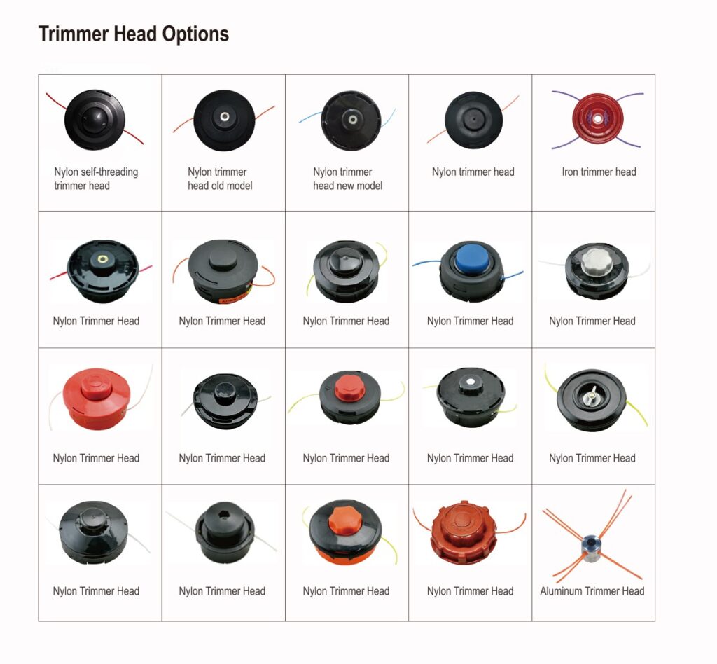
تحدد آلية التغذية كيفية تحرير خط القطع أثناء التشغيل. يؤثر بشكل مباشر على راحة المستخدم, استهلاك الخط, ومتطلبات الصيانة. تم تصميم أنظمة التغذية المختلفة لظروف العمل المختلفة, من تقليم العشب من حين لآخر إلى مهام تنسيق الحدائق الاحترافية المتكررة. تشمل طرق التغذية الأكثر شيوعًا التغذية النتوءية, تغذية تلقائية, وأنظمة الخطوط الثابتة, يقدم كل منها توازنًا مختلفًا بين التحكم, كفاءة, والبساطة.
رؤوس تشذيب الأعلاف
أ نتوء تغذية الانتهازي الرأس يستخدم نظام التخزين المؤقت الذي يطلق خطًا إضافيًا من النايلون عندما ينقر المشغل على الرأس الدوار على الأرض. يؤدي التأثير إلى تنشيط آلية التغذية الميكانيكية, مما يسمح لقوة الطرد المركزي بسحب المزيد من الخط عبر فتحات المخرج. يوفر هذا التصميم تحكمًا جيدًا لأنه يمكن للمستخدمين تحديد وقت تمديد الخط. وتشمل مزاياها عملية بسيطة, توافق واسع, وسهولة الصيانة. لكن, قد يتآكل مقبض الارتطام والمكونات الداخلية بعد التلامس المتكرر مع الأرض, وخاصة في التطبيقات التجارية. تُستخدم رؤوس التغذية ذات النتوءات على نطاق واسع لقطع الحشائش العامة, حواف العشب, وتقليم الحشائش.
اكتشف نيوتوب حلول رأس الانتهازي لقواطع الفرشاة للعثور على خيار الاستبدال المناسب لتطبيقك.
رؤوس تشذيب التغذية الأوتوماتيكية
ان رأس تشذيب التغذية التلقائي يستخدم آلية داخلية لتحرير خط القطع تلقائيًا أثناء التشغيل دون الحاجة إلى قيام المشغل بصدم الرأس. اعتمادا على التصميم, قد يستخدم النظام قوة الطرد المركزي, آلية الربيع, أو بنية تغذية محددة مسبقًا للحفاظ على طول الخط الصحيح. الميزة الرئيسية هي تحسين الراحة, خاصة عند تغطية مناطق واسعة حيث يكون الضبط اليدوي المتكرر غير فعال. لكن, قد تستهلك أنظمة التغذية التلقائية المزيد من الخطوط إذا أطلقت طولًا زائدًا, وعادةً ما تتطلب آلياتها الداخلية تصنيعًا أكثر دقة مقارنةً بتصميمات التغذية الصادمة.
رؤوس تشذيب الخط الثابت
أ رأس تشذيب الخط الثابت يعمل بشكل مختلف عن الأنظمة القائمة على التخزين المؤقت لأنه يستخدم قطعًا فردية مقطوعة مسبقًا من خط النايلون يتم إدخالها مباشرة في الرأس. أثناء العملية, يدور الخط الثابت مع الرأس ويقطع النباتات من خلال تأثير عالي السرعة. يزيل هذا الهيكل مشاكل لف البكرة ويسمح باستبدال الخط بسرعة, مما يجعلها مناسبة للمستخدمين الذين يفضلون الصيانة البسيطة. غالبًا ما يتم استخدام رؤوس الخطوط الثابتة مع خطوط أكثر سمكًا للعشب والأعشاب الضارة. يتمثل القيد الرئيسي في أنه يجب على المشغل استبدال أقسام الخطوط البالية يدويًا بدلاً من تمديد الخط تلقائيًا أثناء القطع.
قم بتوسيع نطاق أعمالك باستخدام معدات الطاقة المتينة

أنواع رؤوس تشذيب الخيوط حسب طريقة تحميل الخط
تصف طريقة تحميل الخط كيفية تثبيت خط القطع الجديد في رأس ماكينة التشذيب. بينما تؤدي جميع الرؤوس القائمة على الخط نفس وظيفة القطع الأساسية, يمكن أن تؤثر تصميمات التحميل الخاصة بها بشكل كبير على سرعة الاستبدال وتجربة المستخدم. تركز أنظمة اللف اليدوية التقليدية على البنية البسيطة والموثوقية, بينما تم تطوير تصميمات البكرات الحديثة سهلة التحميل والملفوفة مسبقًا لتقليل وقت التوقف عن العمل وتسهيل الصيانة.
رؤوس تشذيب الرياح اليدوية
أ رأس تشذيب الرياح اليدوي يتطلب من المشغل أن يقوم بلف خط النايلون يدويًا حول بكرة داخلية قبل التثبيت. يجب أن يتم لف الخط بشكل متساوي وفي الاتجاه الصحيح لضمان التغذية السلسة أثناء التشغيل. يعد هذا التصميم أحد أكثر الأنظمة التقليدية والأكثر استخدامًا بسبب هيكله البسيط, تكلفة التصنيع منخفضة, وأداء موثوق. لكن, يستغرق استبدال الخط وقتًا أطول مقارنةً بأنظمة التحميل السهلة الحديثة, واللف غير الصحيح يمكن أن يسبب انحشار الخط أو التغذية غير المتساوية. تُستخدم رؤوس الرياح اليدوية بشكل شائع في أدوات التشذيب السكنية والمهنية حيث تكون المتانة وكفاءة التكلفة أمرًا مهمًا.
تحميل سهل / رؤوس تشذيب التغذية السريعة
ان رأس تشذيب سهل الحمل أو التغذية السريعة تم تصميمه لتبسيط عملية استبدال الخط عن طريق تقليل الحاجة إلى تفكيك التخزين المؤقت أو لف الخط بأكمله يدويًا. في العديد من التصاميم, يقوم المشغل بإدخال الخط مباشرة من خلال الرأس ويقوم بتدوير التخزين المؤقت لتحميله بالتساوي. يعمل هذا النظام على تحسين كفاءة الصيانة وتقليل وقت التوقف عن العمل, مما يجعلها شائعة بين تنسيق الحدائق المحترفين والمستخدمين التجاريين. الميزة الرئيسية هي تركيب الخط بشكل أسرع, في حين أن العيب هو أن الهيكل عادة ما يكون أكثر تعقيدًا وقد يتطلب دقة تصنيع أعلى مقارنة برؤوس الرياح اليدوية التقليدية.
رؤوس تشذيب بكرة ملفوفة مسبقًا
أ رأس تشذيب البكرة ملفوف مسبقًا يستخدم بكرة بديلة تحتوي على خط نايلون مثبت بالفعل من قبل الشركة المصنعة. عندما يتم استنفاد الخط, يقوم المستخدمون ببساطة بإزالة التخزين المؤقت القديم وتثبيت واحد جديد بدلاً من لف خط جديد يدويًا. وهذا يوفر أسرع وأسهل عملية استبدال, خاصة للمستخدمين العرضيين الذين يعطون الأولوية للراحة. لكن, عادةً ما تكون تكاليف الاستبدال أعلى للبكرات سابقة اللف وتتطلب من المستخدمين شراء أحجام بكرة متوافقة. يوجد هذا النوع بشكل شائع في أدوات التشذيب الكهربائية والتي تعمل بالبطارية من الفئة الاستهلاكية حيث تعد سهولة الاستخدام عامل شراء رئيسي.
أنواع رؤوس تشذيب الخيوط عن طريق القطع المتوسط
وسيلة القطع هي المادة الفعلية التي تتصل بالنباتات وتزيلها. توفر المواد المختلفة مستويات مختلفة من قوة القطع, المرونة, متانة, والسلامة. يستخدم خط النايلون بشكل شائع لتقليم العشب العام, بينما تم تصميم الشفرات المعدنية والأنظمة القائمة على الأسلاك لتناسب النباتات الأكثر صرامة أو التطبيقات المتخصصة.
رؤوس تشذيب خط النايلون
رؤوس تشذيب خط النايلون هي أنظمة القطع الأكثر شيوعًا المستخدمة لقص العشب و قواطع الفرشاة. إنهم يعتمدون على خط نايلون مرن يدور بسرعة عالية لقطع العشب والأعشاب الضارة من خلال قوة التأثير. أقطار خط مختلفة, الأشكال, والمواد يمكن أن تؤثر على المتانة, كفاءة القطع, ومقاومة الكسر. توفر رؤوس النايلون أمانًا ممتازًا لأن الخط المرن من غير المرجح أن يسبب ضررًا عند ملامسة الأسطح الصلبة. لكن, فهي أقل فعالية ضد الفرشاة السميكة, ينبع خشبية, أو نباتات كثيفة. فهي مثالية لصيانة الحديقة, حواف التشذيب, وتطبيقات المناظر الطبيعية العامة.
رؤوس تشذيب الشفرة
أ رأس تشذيب الشفرة يستخدم شفرات معدنية صلبة بدلاً من خط النايلون المرن لتوفير أداء قطع أقوى. تقوم الشفرة الدوارة بقطع النباتات من خلال الاتصال المباشر, مما يجعلها مناسبة للعشب الكثيف, الأعشاب الثقيلة, وفرشاة صغيرة قد تتآكل بسرعة خط النايلون. توفر أنظمة الشفرات قوة قطع أعلى وعمر خدمة أطول في التطبيقات كثيرة المتطلبات, ولكنها تتطلب آلات أقوى, حراس السلامة المناسبة, والتثبيت الصحيح. لأن الشفرات المعدنية تولد قوى تأثير أعلى, يتم استخدامها بشكل أساسي مع قواطع الفرشاة الاحترافية بدلاً من أدوات تشذيب الخيوط السكنية خفيفة الوزن.
رؤوس تشذيب فرشاة الأسلاك والأسلاك
رؤوس تشذيب الأسلاك والفرشاة السلكية استخدم عناصر الأسلاك المعدنية أو مواد القطع على شكل فرشاة لإزالة النباتات القاسية, طحلب, الأعشاب, والنمو السطحي. بدلاً من القطع بحافة حادة, يخلق السلك الدوار عملية تنظيف وقطع كاشطة. يمكن أن تكون هذه الرؤوس مفيدة للمهام المتخصصة مثل إزالة الأعشاب الضارة بين حجارة الرصف أو تنظيف الأسطح الصلبة.
أنواع رؤوس تشذيب السلسلة حسب تكوين مخرج الخط

يشير تكوين مخرج الخط إلى عدد وترتيب أطراف خط القطع الممتدة من رأس ماكينة التشذيب. يؤثر هذا التصميم على تغطية القطع, كفاءة, والحمل الموضوع على محرك أو محرك التشذيب. عادةً ما يتم تصميم أنظمة الخط الواحد للتطبيقات الأخف, بينما توفر الرؤوس ذات الخطوط المزدوجة والمتعددة الخطوط أداء قطع متزايدًا للمناطق الأكبر وظروف العشب الأثقل.
رؤوس تشذيب أحادية الخط
أ رأس تشذيب ذو خط واحد يستخدم قطعة واحدة من خط النايلون الممتد من الرأس أثناء التشغيل. لأنه يحتوي على عدد أقل من المكونات المتحركة ومقاومة دوران أقل, غالبًا ما يتم استخدامه في أدوات التشذيب خفيفة الوزن المصممة للعناية بالعشب السكني. توفر أنظمة الخط الواحد عملية مستقرة, استهلاك الخط السفلي, وسهولة الصيانة مقارنة بالتصميمات متعددة الخطوط. لكن, أنها توفر بشكل عام تغطية أقل للقطع وكفاءة قطع أقل عند التعامل مع النباتات الكثيفة. إنها مناسبة للتقليم الخفيف, حواف العشب, والمناطق التي تكون فيها الدقة أكثر أهمية من سرعة القطع القصوى.
رؤوس تشذيب ثنائية الخطوط ومتعددة الخطوط
أ رأس تشذيب مزدوج الخط أو متعدد الخطوط يستخدم طرفين أو أكثر من خطوط القطع الممتدة من الرأس, زيادة عدد نقاط القطع أثناء الدوران. يعمل هذا التصميم على تحسين كفاءة القطع ويسمح للآلة بإزالة المزيد من النباتات مع كل دورة. تُستخدم الرؤوس متعددة الخطوط بشكل شائع في تطبيقات العشب الأثقل والمناظر الطبيعية الاحترافية. لكن, يزيد الخط الإضافي من مقاومة الهواء ويضع حملاً أكبر على المحرك أو المحرك. لذلك, تتطلب هذه الرؤوس طاقة كافية للماكينة واختيارًا مناسبًا لقطر الخط للحفاظ على الأداء وتجنب التآكل المفرط.
أنواع رؤوس التشذيب ذات الشفرات المعدنية حسب تصميم الشفرة
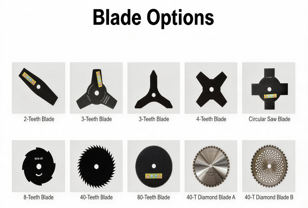
تُستخدم رؤوس الشفرات المعدنية بشكل أساسي في قواطع الفرشاة ومعدات التشذيب شديدة التحمل حيث لا يستطيع خط النايلون توفير قوة قطع كافية. شكل الشفرة, رقم الأسنان, ويحدد الهيكل العام مدى كفاءة الشفرة في قطع أنواع مختلفة من النباتات.
2-شفرات الأسنان المستقيمة
أ 2-شفرة الأسنان المستقيمة تتميز بحافتي قطع متوضعتين مقابل بعضهما البعض على قرص الشفرة. يوفر تصميمه البسيط توازنًا جيدًا, انخفاض الوزن الدوار, وأداء قطع فعال للنباتات الخفيفة. لأنه يحتوي على عدد أقل من الأسنان, يمكنها الحفاظ على سرعة دوران عالية مع طلب أقل للطاقة مقارنة بالشفرات متعددة الأسنان. تُستخدم هذه الشفرات عادةً لقطع العشب والأعشاب الناعمة. لكن, فهي ليست مصممة للفرشاة الكثيفة أو النباتات الخشبية لأن العدد المحدود من حواف القطع يقلل من قدرتها على التعامل مع المواد الأكثر صرامة.
3-شفرات الأسنان
أ 3-شفرة الأسنان هي واحدة من شفرات قطع الفرشاة الأكثر استخدامًا لأنها توفر التوازن بين قوة القطع, يتحكم, والتنوع. تقوم حواف القطع الثلاثة بتوزيع قوة التأثير بشكل متساوٍ مع الحفاظ على الدوران الفعال. هذا التصميم مناسب للعشب متوسط الكثافة, الأعشاب, والإدارة العامة للغطاء النباتي. بالمقارنة مع الشفرات ذات الأسنان, 3-توفر تصميمات الأسنان تغطية قطع محسنة, مع الحفاظ على وزن خفيف بما يكفي للعديد من قواطع الفرشاة.
4-شفرات الأسنان
أ 4-شفرة الأسنان يوفر حواف قطع إضافية مقارنة بالتصميمات ذات السنتين والثلاثة أسنان, تحسين اتساق القطع عند العمل من خلال نباتات أكثر سمكًا. يسمح العدد المتزايد للأسنان بالاتصال المتكرر بالنباتات أثناء الدوران, والتي يمكن أن تحسن كفاءة القطع. لكن, تعمل المادة الإضافية أيضًا على زيادة وزن الشفرة وتتطلب طاقة الماكينة المناسبة. غالبًا ما تُستخدم الشفرات ذات الأربع أسنان للعشب الأثقل والأعشاب الضارة حيث يحتاج المستخدمون إلى أداء أقوى من أنظمة خطوط النايلون القياسية ولكن لا يحتاجون إلى شفرة منشار دائري.
شفرات منشار دائري
أ شفرة منشار دائري يستخدم أسنانًا حادة متعددة حول الحافة الخارجية, على غرار المنشار التقليدي. على عكس شفرات قطع العشب, إنه مصمم للتعامل مع النباتات الأكثر صرامة, بما في ذلك فرشاة سميكة, سيقان خشبية صغيرة, والشتلات الشابة. يوفر العدد الكبير من الأسنان أداءً قويًا للقطع, ولكنه يتطلب أيضًا قوة محرك أعلى, تركيب الشفرة الصحيح, وممارسات التشغيل المهنية. تُستخدم شفرات المنشار الدائري عادةً مع قواطع الفرشاة شديدة التحمل ويجب تركيبها فقط على الآلات المصممة خصيصًا لدعم هذا النوع من ملحقات القطع.
تصميمات الشفرة المقطوعة والمجوفة
تصميمات شفرات مقصوصة ومجوفة استخدم الفتحات أو مناطق المواد المخفضة في جسم الشفرة لتقليل الوزن مع الحفاظ على قوة القطع. تساعد هذه التصميمات على تقليل الكتلة الدوارة, تحسين توازن الآلة, وتقليل إجهاد المشغل أثناء الاستخدام الممتد. يمكن للهيكل المقطوع أيضًا تحسين التعامل عن طريق تقليل المقاومة أثناء الدوران. تم تطوير أنماط فتح مختلفة لظروف نباتية محددة, من إدارة العشب إلى قطع الفرشاة الثقيلة. كما هو الحال مع جميع الشفرات المعدنية, يعتمد الأداء على مطابقة تصميم الشفرة مع قوة قطع الفرشاة, نظام الحراسة, وبيئة العمل المقصودة.
كيفية اختيار رأس التشذيب المناسب لحديقتك
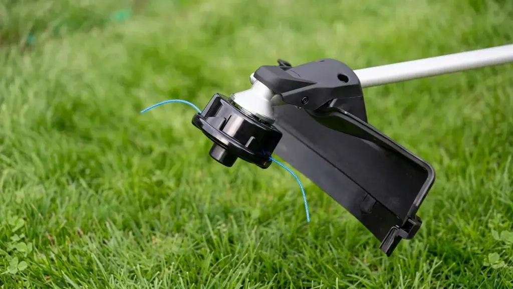
ابدأ بـ الغطاء النباتي, ثم فكر في الآلة.
للعشب العادي والحواف, عادةً ما يكون رأس خط النايلون هو الخيار الأكثر عملية. يمكن أن يؤدي تصميم التغذية التلقائية أو التغذية التلقائية إلى تسهيل ضبط الخط بشكل متكرر.
للأعشاب الكثيفة والعشب الطويل, اختر رأسًا أقوى وقطر خط مناسب. إذا أصبح الغطاء النباتي خشبيًا أو يشبه الفرشاة, قد توفر الشفرة المعدنية المتوافقة أداء قطع أفضل.
يجب عليك أيضا أن تنظر:
- قوة الآلة: تتطلب الرؤوس والشفرات الثقيلة قوة محرك مناسبة.
- مواد القطع: خط النايلون مناسب للتقليم العام; الشفرات أفضل للنباتات الأكثر صرامة.
- قطر الخط: يوفر الخط الأكثر سمكًا متانة أكبر ولكنه يزيد من حمل الماكينة.
- تردد العمل: قد يستفيد المستخدمون التجاريون من أنظمة التحميل السهل أو التغذية السريعة.
- صيانة: يمكن تفضيل الرأس البسيط عندما تكون الخدمة السريعة مهمة.
كيفية مطابقة رأس التشذيب مع قطر الخط
يجب أن يتطابق قطر الخط مع كل من رأس الانتهازي وقوة الآلة.
يعتبر الخط الرفيع مناسبًا بشكل عام للعشب الخفيف ويتطلب طاقة أقل للتسريع. يوفر الخط السميك مقاومة أفضل للتآكل والكسر وهو أكثر ملاءمة للعشب والأعشاب الكثيفة.
لكن, إن استخدام الخط الأكثر سمكًا ليس هو الأفضل دائمًا. الخط الكبير الحجم يمكن أن يزيد من حمل المحرك, تقليل سرعة الدوران, وتتداخل مع آلية التغذية.
تحقق دائمًا من قطر الخط الموصى به من قبل الشركة المصنعة لرأس أداة تشذيب السلسلة قبل التغيير من المواصفات الأصلية.
كيفية معرفة ما إذا كان رأس ماكينة التشذيب يناسب ماكينة تشذيب الخيوط الخاصة بك
يجب أن يتوافق الرأس البديل مع المواصفات الميكانيكية والتشغيلية للماكينة. يفحص:
- تصاعد الموضوع واتصال رمح
- متطلبات المحول
- اتجاه الدوران
- الحد الأقصى لقطر الخط
- الحد الأقصى لقطر القطع
- قوة المحرك أو المحرك
- وزن الرأس
- التوافق مع طراز الآلة
على المدى “رأس تشذيب عالمي” لا يعني أن رأسًا واحدًا يناسب كل أداة تشذيب للخيوط. تدعم المنتجات العالمية عادةً العديد من أنظمة التثبيت الشائعة من خلال المحولات.
لمشتري الجملة وموزعي المعدات, يعد التحقق من قائمة التوافق الدقيقة أكثر أمانًا من اختيار رأس بناءً على المظهر أو حجم الخيط فقط.
رؤوس تشذيب السلاسل من نيوتوب لتطبيقات مختلفة
نيوتوب توفر رؤوس تشذيب الخيوط وملحقات قطع الفرشاة للعشب المختلفة, حشيش, والتطبيقات النباتية. تتضمن مجموعة المنتجات هياكل رأس مختلفة وتكوينات تركيب لدعم نماذج قطع الفرشاة المختلفة.
للموزعين والمستوردين, لا يقتصر اختيار رأس القطع على الملحق الفردي فقط. الرأس, خط النايلون, شفرة, قطع الفرشاة, ويجب أن يعمل التطبيق كنظام قطع كامل.
يمكن لـ NEWTOP دعم العملاء الذين يبحثون عن معدات الطاقة الخارجية ومكونات القطع البديلة لمتطلبات السوق المختلفة, بما في ذلك اختيار المنتجات ومصادر الجملة.
هل تبحث عن رؤوس تشذيب الخيوط أو أنظمة قطع الفرشاة لسوقك? اتصل بـ NEWTOP لمناقشة النماذج المناسبة, تحديد, وخيارات المصادر.
الأسئلة المتداولة
ما هي الأنواع المختلفة لرؤوس تشذيب الخيوط?
يمكن تصنيف رؤوس تشذيب السلسلة حسب آلية التغذية, طريقة التحميل, وسط القطع, تكوين منفذ الخط, وتصميم الشفرة. وتشمل الأنواع الشائعة تغذية نتوء, تغذية تلقائية, الخط الثابت, الرياح اليدوية, سهل الحمل, بكرة ملفوفة مسبقًا, خط النايلون, ورؤوس الشفرات المعدنية.
ما هو رأس تشذيب الأعلاف?
يقوم رأس التغذية النتوء بتخزين الخط على بكرة داخلية. عندما يلبس الخط, ينقر المشغل على الرأس الدوار على الأرض. يؤدي هذا إلى ضغط آلية الزنبرك لتحرير قصيرة, إمكانية التحكم في كمية الخط دون الحاجة إلى إيقاف الماكينة.
هل رؤوس التشذيب العالمية عالمية حقًا؟?
ليس بالضرورة. تناسب الرؤوس العامة عادةً العديد من أنظمة التثبيت الشائعة بدلاً من كل أدوات التشذيب المتوفرة في السوق. تحقق دائمًا من الخيط, محول, اتجاه الدوران, سعة الخط, وتوافق الجهاز قبل التثبيت.
ما هو أسهل رأس تشذيب يمكن تحميله؟?
تعتبر رؤوس الصدمات ذات التغذية السريعة أو سهلة التحميل هي الأسهل على نطاق واسع لإعادة التحميل. تتميز بمسار تحميل خارجي حيث تقوم بدفع الخط مباشرة من خلال الثقوب ولف المقبض أو اللوحة لتحريكه. وهذا يلغي الحاجة إلى فتح الغطاء أو لف البكرة يدويًا, في كثير من الأحيان تأخذ تحت 30 ثواني.
هل يمكنني وضع رأس خط ثابت على أداة تشذيب الخيوط الخاصة بي؟?
نعم, بشرط أن يتطابق رأس الخط الثابت مع حجم شجرة أداة التشذيب الخاصة بك, اتجاه الخيط, وتصنيف الطاقة. لأن رؤوس الخطوط الثابتة غالبًا ما تستخدم خطًا أكثر سمكًا مخصصًا للفرشاة الثقيلة والأعشاب الضارة, إنها تؤدي أداءً أفضل على أدوات تشذيب الغاز الأكبر حجمًا بدلاً من الوحدات الاستهلاكية منخفضة الطاقة.
ما هو الفرق بين رؤوس التشذيب الأوتوماتيكية ورؤوس التغذية?
الفرق الرئيسي يأتي إلى تحكم المستخدم. يتطلب رأس التغذية النتوءية النقر يدويًا على الأرض للتقدم بالخط, مما يساعد على تقليل الخط الضائع. يستشعر الرأس التلقائي عندما يكون الخط قصيرًا أو يتغير حمل المحرك ويتقدم الخط من تلقاء نفسه, توفير القطع المستمر ولكن عادةً ما يستهلك الخط بشكل أسرع.
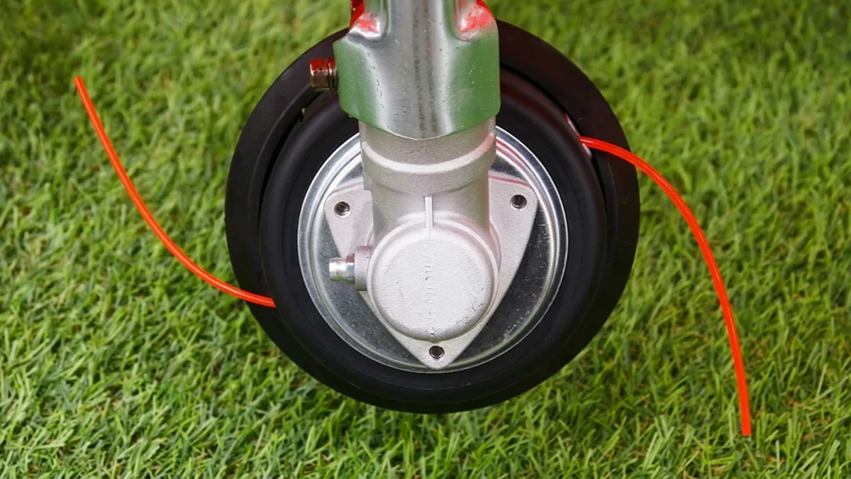
Choosing the right string trimmer line size can make yard work faster, cleaner, and much easier. Use a line that is too thin, and it may snap repeatedly when cutting thick grass or weeds. Choose one that is too thick, and your trimmer may lose cutting speed, use more power, or put extra load on the trimmer head.
لذا, what diameter should you use? Is 0.080″ enough for normal grass, or is 0.095″ better for weeds? When does it make sense to move up to 0.105″ or 0.130″?
This guide breaks down common string trimmer line diameters, explains which sizes work best for different yard conditions, and compares popular line shapes. Whether you are maintaining a small lawn or tackling dense weeds and heavy vegetation, you will learn how to match the line to both the job and your trimmer.
What Is String Trimmer Line?
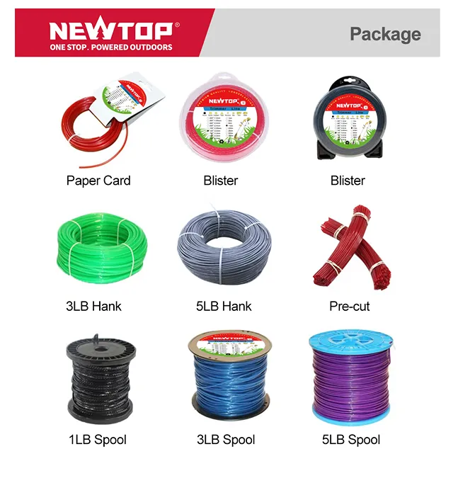
String trimmer line, also called trimmer cord or weed eater line, is the flexible cutting material used by string trimmers and brush cutters. It rotates at high speed around the trimmer head and cuts grass and weeds through impact and friction.
القراءة ذات الصلة: أنواع رؤوس تشذيب الخيوط
Most trimmer lines are made from durable nylon or nylon-based materials. Some professional-grade lines use reinforced or co-extruded materials to improve wear resistance and reduce breakage.
The line diameter is one of the most important specifications. Common sizes range from about 0.065 (1.65 مم) inches to 0.155 بوصة (3.94 مم), although some heavy-duty machines can use larger diameters.
A larger diameter generally provides:
- Better durability
- Higher resistance to breaking
- Better performance in thick vegetation
- More cutting power for demanding jobs
لكن, thicker does not always mean better. The trimmer head and engine must be designed to handle the selected line.
What String Trimmer Line Sizes Are Available?
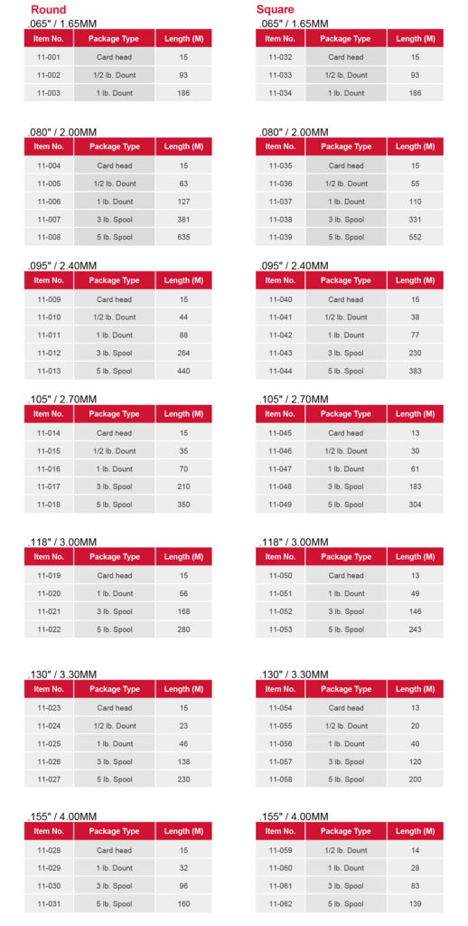
String trimmer line is commonly sold by diameter in inches. The most widely used sizes include 0.065″, 0.080″, 0.095″, 0.105″, and 0.130″.
Smaller diameters are suitable for light grass and residential trimming. Medium diameters provide a balance between cutting performance and durability. Larger diameters are designed for thick weeds, نباتات كثيفة, and heavier-duty work.
The table below gives a quick overview:
| Line Diameter | تطبيق نموذجي | Cutting Conditions |
|---|---|---|
| 0.065″–0.080″ (1.65–2.03 mm) |
Light trimming | Soft grass and lawn edges |
| 0.080″–0.095″ (2.03–2.41 mm) |
General yard work | Regular grass and moderate weeds |
| 0.095″–0.105″ (2.41–2.67 mm) |
Heavy residential or professional use | Thick grass and tough weeds |
| 0.105″–0.130″ (2.67–3.30 mm) |
Heavy-duty cutting | Dense weeds and rough vegetation |
| 0.130″+ (3.30 mm+) |
Professional heavy-duty work | Heavy brush and demanding conditions |
High-Margin Garden Equipment for Global Distributors
How to Choose String Trimmer Line Size for Different Grass Types
For soft lawn grass, a smaller line can provide fast cutting with less engine load. For thick, dry, or tough grass, a medium or large diameter is usually more suitable because it can withstand repeated impacts.
Consider three factors:
Grass density: Dense grass creates more resistance against the line.
Stem toughness: Tough weeds and dry vegetation require a stronger cutting line.
قوة الآلة: A larger line needs more rotational energy. A small trimmer may struggle with oversized cord.
قصير, Soft Turf and Light Edging
Fine turf species like Kentucky bluegrass, fescue, and ryegrass require a gentle touch to avoid scalping. A thinner diameter protects delicate flower beds, sprinkler heads, and patio edges during routine maintenance.
Using a lightweight cord prevents small electric trimmers from bogging down while spinning. For these manicured areas, rely on the following specifications:
- Recommended diameter: 0.065″ to 0.080″ round line
- Target vegetation: Soft turf kept at standard mowing heights
- Key benefit: Minimizes tearing of thin grass blades
Standard Residential Lawns and Mixed Weeds
Most typical suburban yards feature a mix of regular turf and common weeds like dandelions, clover, and young crabgrass. You need a versatile cord that handles weekly perimeter maintenance along fences, driveways, and trees without breaking every five minutes.
This category hits the sweet spot for mid-range gas and 40-56V battery trimmers, offering a perfect balance between cutting strength and flexibility.
- Recommended diameter: 0.080″ to 0.095″
- Primary application: Default all-purpose residential use
- Optimal equipment: Mid-range gas and 40-56V battery units
Thick Turf, Mature Grass, and Tough Weeds
Neglected yard corners and overgrown sections quickly outmatch standard homeowner line. When facing thick-stemmed weeds like mature plantain or coarse sedges, you need a cord with enough physical mass to maintain its momentum.
A heavier cord slices straight through dense clumps instead of folding over on impact. It also resists rapid fraying and snapping when making repeated contact with retaining walls or concrete foundations.
- Recommended diameter: 0.085″ to 0.110″
- Target vegetation: Mature grass and tough, fibrous stems
- Durability advantage: Survives heavy impact with hard landscape obstacles
Tall Grass, Dense Brush, and Heavy Vegetation
Clearing coarse pasture grass, drainage ditches, nettles, and brambles demands serious cutting power. This rough terrain pushes string trimmers to their absolute limits, often requiring heavy-duty lines to tear through small woody saplings.
Operators working in these extreme conditions frequently switch from round lines to square, serrated, or twisted profiles. These aggressive shapes bite directly into fibrous stems for faster clearing.
- Recommended diameter: 0.110″ and above (often 3.0 mm to 3.3 mm+)
- Equipment requirement: Commercial-grade trimmers or walk-behind brush cutters
- Preferred profiles: Square, serrated, or twisted shapes
Aligning Line Size with Trimmer Power
Matching your cord thickness to the vegetation is only half the battle; the machine must actually possess the torque to spin it. Installing a line thicker than the manufacturer’s maximum rating reduces RPMs, resulting in battered, torn grass instead of clean cuts.
Engine displacement and battery voltage strictly dictate what your machine can handle safely.
- Under 40V Electric/Battery: Requires 0.065″ to 0.080″ line to prevent motor strain and overheating.
- Mid-Power Units (20-30 cc gas or 40-56V battery): Optimized to efficiently spin 0.080″ to 0.095″ line.
- Commercial Units (30 cc+ gas): Built to operate 0.095″ to 0.130″+ line without losing critical tip speed.
What Size Trimmer Line Is Best for Light Grass and Small Yards?

For light grass and small yards, stick strictly to 0.065 or 0.080-inch trimmer line. This range maximizes RPMs on low-voltage equipment while preventing damage to delicate hardscapes.
The Core Size Range: 0.065 ل 0.080 Inch
The industry-standard size for light grass and small residential trimming falls strictly between 0.065 و 0.080 بوصة (1.65–2.03 mm). Manufacturers build lightweight consumer trimmer heads specifically around these tolerances to ensure smooth feeding.
A 0.065-inch line is the optimal choice for very light-duty tasks. It excels at touching up short grass and executing clean edges around delicate flower beds without tearing the turf.
A 0.080-inch line provides a slightly more robust, versatile option. It tackles yards requiring regular maintenance and holds up better against minor impacts with garden borders.
Why Thinner Line Suits Small Yard Equipment
Thinner line is highly aerodynamic. This minimal drag allows low-power electric and battery trimmers operating under 40V to maintain high RPMs without overloading the motor.
Using oversized line on small-yard tools causes immediate mechanical stress. It triggers faster battery drain, excessive vibration, and premature wear on drive components.
Round line under 0.080 inches also offers high precision around tight obstacles. You can maneuver close to borders, reducing the risk of scarring tree bark or damaging expensive hardscapes.
Choosing Between 0.065 و 0.080 Inch
Select 0.065-inch line for small, regularly mowed yards featuring soft turf. It pairs perfectly with low-voltage, lightweight trimmers handling basic detail work.
Upgrade to 0.080-inch line if the yard occasionally features taller grass or small weeds. This diameter performs much better for frequent edging against concrete walkways, where thinner cords snap on contact.
Small gas trimmers under 25 cc handle 0.080-inch line comfortably. It offers better resistance to fraying and snap-offs than thinner alternatives, keeping your workflow steady.
What Size Trimmer Line Is Best for Thick Grass and Weeds?

For thick grass and heavy weeds, the 0.095-inch line is the versatile standard. Step up to 0.105-inch for overgrown stalks, provided your equipment has the power.
The Optimal Range: 0.095″ مقابل. 0.105″ Line
The 0.095-inch (2.4 مم) line acts as the most versatile option for thick turf and heavy residential yard work. It strikes a balance between cutting power and flexibility, allowing you to clear dense patches without immediately bogging down standard landscape equipment.
The 0.105-inch (2.7 مم) line offers superior strength for overgrown grass, thick-stemmed weeds, and intense fence line clearing. Users should start with the 0.095-inch line and only upgrade to the 0.105-inch variant if the line snaps frequently against dense stalks or hard borders.
Matching Line Size to Equipment Power
Mid-range gas trimmers in the 20 ل 30 cc category and 40V+ battery units generate enough torque to run 0.095-inch lines efficiently. These machines can maintain the high rotational speeds required to cut cleanly through tough vegetation.
Low-voltage battery models struggle with heavy lines, often resulting in sluggish performance or severe motor strain. Operators must verify the maximum supported diameter in the equipment manual before installing a thicker string to prevent drive system failure.
How Diameter Affects Cutting Efficiency and Durability
String trimmers rely on tip velocity and weight to perform work. Larger diameters carry more physical mass, delivering the momentum needed to slice right through coarse, fibrous vegetation instead of just bending it over.
Upgrading to a 0.095-inch or 0.105-inch size drastically reduces breakage when striking hard surfaces like concrete walls or wood retaining posts. Selecting the smallest effective diameter for your specific terrain prevents unnecessary engine drag and optimizes battery runtimes for long shifts.
What Size Trimmer Line Is Best for Heavy-Duty Brush?

Heavy-duty brush requires line diameters between 0.110 و 0.155 بوصة. To maintain cutting speed and protect the clutch, always match these thicker lines to commercial-grade engine displacements.
Recommended Line Sizes by Brush Density
Thick, woody brush destroys standard residential trimmer line on impact. To clear dense undergrowth efficiently, you need mass and rigidity. Operators categorize heavy-duty string trimmer line into three primary bands based on vegetation density.
- 0.095 ل 0.105 بوصة: Suited for heavy weeds, thick grass, and light brush using high-powered residential trimmers.
- 0.110 ل 0.130 بوصة: Ideal for thick brush, woody shrubs, and dense vegetation in commercial-grade clearing work.
- 0.155 inch and above: Reserved for extreme-duty clearing and heavy commercial applications.
Matching Line Diameter to Engine Displacement
Pushing a thick line through dense brush creates massive drag. Thicker lines resist breakage but demand significantly more engine torque to maintain cutting speed. If your engine lacks the output to spin a heavy line at peak RPM, the trimmer bogs down and batters the vegetation.
- 25 ل 35 cc engines: Perform best with 2.7 ل 3.0 مم (تقريبا. 0.110 بوصة) line.
- 40 cc engines: Provide the necessary torque for 3.0 ل 3.5 مم (تقريبا. 0.130 بوصة) line.
- 40 ل 50 cc or larger engines: Required to effectively spin 3.5 ل 4.5 مم (0.155 inch and thicker) line.
Choosing the Right Line Shape for Heavy Brush
Profile geometry dictates how the line interacts with woody stems. You must weigh raw cutting power against material wear and motor strain.
- Round line: Offers high durability and resists breaking against hard stems, making it a reliable choice for everyday heavy clearing.
- Square, serrated, or twisted line: Delivers a more aggressive cut through thick brush but tends to wear faster.
Aggressive line profiles place higher drag on the trimmer head. You need adequate engine power to prevent the machine from bogging down when those sharp edges bite into thick stalks.
Equipment Limitations and Capacity Bounds
Manufacturers engineer trimmer heads and clutches for specific load limits. Forcing an oversized line into a head not rated for it guarantees mechanical failure.
- Poor cutting performance: Using a line thicker than the trimmer’s rating causes poor cutting performance and accelerates head wear.
- Mechanical overload: Excessive line weight puts unnecessary strain on the engine and clutch system.
- Strict upper limits: Always treat the manufacturer’s specified maximum line diameter as a strict upper limit to protect the equipment.
Round vs Square vs Star-Shaped Trimmer Line
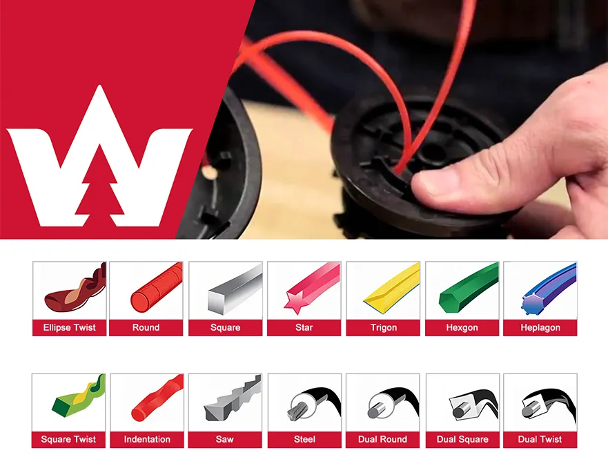
Round line is the most common type. Its smooth surface provides good durability and works well for general grass and weed trimming. It is also less likely to wear unevenly.
Square line has sharper edges that can provide more aggressive cutting on thick grass and weeds. It may be useful for demanding vegetation but can wear differently depending on the working conditions.
Star-shaped or multi-sided line has multiple cutting edges. It is designed to improve cutting efficiency and can perform well on tougher vegetation.
The best shape depends on the job. For everyday lawn maintenance, round line is a reliable choice. For heavier vegetation, square or multi-sided line may provide more aggressive cutting.
Best Applications and Diameter Selection
Match the line shape and diameter directly to the yard conditions and your specific equipment capacity.
- Round Line (0.065-0.095 بوصة): Use for regular weekly maintenance on typical residential yards using battery or small gas trimmers.
- Square Line (0.080-0.105 بوصة): Step up to this size for tackling overgrown fence lines, ditch banks, and medium-to-heavy vegetation.
- Star-Shaped Line (0.090+ بوصة): Reserve these large diameters for heavy-duty cleanup of coarse grasses, الحشائش السميكة, and neglected lots.
How to Know Which Trimmer Line Size Your Machine Needs
Match your trimmer line size to your machine’s manual, power output, and the target vegetation. Getting this right maximizes cutting performance and prevents equipment damage.
Check the Owner’s Manual or Trimmer Head
The fastest way to find your required line size is to consult the original documentation. Open your owner’s manual and scan for specifications labeled as cutting line, line diameter, spool capacity, or recommended line size. Manufacturers engineer the trimmer head to operate within these exact tolerances.
If you lost the manual, inspect the equipment directly. You can often find the printed or molded dimensions on the trimmer head, spool cover, or housing. Once you find this number, treat it as a hard limit. Stay strictly within the manufacturer’s specified range rather than choosing by appearance or feel at the hardware store.
Match Line Size to Trimmer Power and Type
Trimmer power directly dictates how thick of a line the motor can spin efficiently. Mismatching the line thickness overloads the drive system and slows down the RPMs.
- Electric and battery-powered trimmers: Generally require smaller diameters, commonly between 0.065 و 0.080 بوصة (1.6 ل 2.0 مم).
- Residential gas trimmers: Support mid-range to thicker lines, often ranging from 0.080 ل 0.110 بوصة.
- Commercial brush cutters: Handle the thickest lines, starting at 0.110 inches and scaling up to 0.155 inches for high-power units.
Matching the line to the motor ensures the tip speed stays high. High tip speed is exactly how the tool slices cleanly through grass instead of just battering it.
Select the Right Diameter for the Vegetation
Once you know what sizes your machine accepts, select the specific diameter based on your yard conditions. Thicker lines deliver more impact force, but they also create more drag.
- 0.065 to 0.080-inch line: Use for light grass, متفوقا, sidewalks, and fences.
- 0.080 to 0.095-inch line: Choose for general lawn maintenance and thicker grass.
- 0.095 to 0.110-inch line (or higher): Opt for heavy weeds, dense growth, and woody stems.
The smartest approach is to apply the smallest line size that reliably completes the task. A thinner line cuts cleaner and minimizes mechanical strain on your machine.
Common Mistakes to Avoid
Many operators try to force a heavier line to do a job the machine wasn’t built to handle. This creates a cascade of mechanical and performance issues.
- Overloading the head: Installing a thicker line than the trimmer is designed for drops cutting performance and damages the head assembly.
- Copying old spools blindly: Buying replacement line based solely on the size of the old spool causes errors, especially if a previous owner modified or replaced the trimmer head.
- Ignoring the limits: Exceeding the maximum allowed diameter just because a thicker line physically fits into the spool housing will overheat the motor.
Stick strictly to the manufacturer specifications. A fast-spinning thin line always outcuts a slow, bogging thick line.
Common String Trimmer Line Problems and Solutions
Even the correct diameter can perform poorly if the line is installed or used incorrectly.
| Problem | Possible Cause | Solution |
|---|---|---|
| Line breaks frequently | Line is too thin or worn | Use the recommended diameter and replace worn line |
| Line does not feed | Incorrect winding | Rewind evenly in the correct direction |
| Poor cutting performance | Line too thin or worn | Use a suitable diameter and fresh line |
| Engine slows down | Line is too thick | Use the manufacturer’s recommended size |
| Line welds together on spool | Excessive heat or poor line material | Use quality line and store it correctly |
| Uneven cutting | Different line lengths | Rewind and adjust both sides evenly |
How to Replace String Trimmer Line
Replacing trimmer line requires matching the exact diameter to your head style, winding it tightly in the designated direction, and testing the feed mechanism before operation.
Safety Checks and Trimmer Preparation
Preparation ensures you do not accidentally trigger the equipment while working near the cutting head. Securing the tool properly speeds up the replacement process.
- Power disconnection: Disconnect the power source by unplugging the cord, removing the battery, or detaching the spark plug.
- Tool positioning: Place the trimmer on a flat surface with the head facing up to provide clear access to the spool.
- Head identification: Identify the specific head style, such as a standard manual-wrap reel, a bump-feed head, or a quick-load system.
Removing the Old Line and Cleaning the Head
Old debris causes friction and stops new line from feeding properly. You need to clear the housing completely before loading fresh cord.
- Head opening: Open the trimmer head by pressing the side release tabs or twisting off the central bump knob.
- Spool removal: Pull the spool out of the housing and completely unravel any leftover string.
- Debris clearance: Wipe away accumulated grass, الأوساخ, and mud from the spool and housing to prevent future jamming.
Selecting and Cutting the New Trimmer Line
Using the wrong line thickness or leaving ragged edges will cause immediate feed issues. Cut the cord cleanly to match your specific equipment ratings.
- Diameter selection: Select the appropriate diameter for the job, typically ranging from 0.065 inches for light grass to 0.095 inches for heavy weeds.
- Length measurement: Measure and cut the manufacturer-recommended length, which usually falls between 10 و 25 feet per spool.
- Clean cuts: Use sharp cutters to create clean ends, preventing fraying that makes threading difficult.
Winding the Line Onto the Spool
Loose or crossed lines trap heat and melt together during operation. Winding requires consistent tension and correct alignment.
- Anchor location: Locate the starting anchor hole and the directional arrow printed on the spool.
- Tension application: Wind the line tightly and evenly side-to-side in the direction of the arrow to avoid overlapping or binding.
- End securing: Stop winding when about six inches remain, securing the loose ends into the holding slots on the spool rim.
Reassembling the Trimmer Head
The spool must seat perfectly into the housing for the bump mechanism to function without jamming or failing under high RPMs.
- Eyelet threading: Thread the free ends of the line through the exit eyelets located on the sides of the trimmer head housing.
- Spool seating: Push the wound spool down onto the central spindle until it seats firmly into place.
- Cover locking: Replace the outer cover or bump knob, snapping or twisting it until securely locked.
Final Testing and Adjustments
Before returning to active yard work, verify the feed system operates correctly under normal operating speed.
- Power restoration: Reconnect the battery, power cord, or spark plug.
- System testing: Turn on the trimmer and activate the feed mechanism, such as tapping the bump head on the ground, to verify smooth operation.
- Length calibration: Allow the line cutter blade on the trimmer guard to automatically trim any excess length as the head spins.
الأفكار النهائية
Choosing the right string trimmer line size is a balance between cutting performance, متانة, and machine compatibility.
For light grass and small yards, 0.065″–0.080″ line is often enough. For general grass and weeds, 0.080″–0.095″ provides a useful balance. Tough weeds and heavy vegetation may require 0.105″–0.130″ line, provided that the trimmer is designed for it.
The most important rule is simple: do not choose line diameter based on thickness alone. Match the line to the vegetation and the specifications of the trimmer head and engine.
Looking for a reliable outdoor power equipment partner? نيوتوب provides complete trimmer and brush cutter solutions for manufacturers, الموزعين, والمستخدمين المحترفين. Contact NEWTOP today to discuss your product requirements and develop the right cutting system for your market.
الأسئلة المتداولة
What size trimmer line should I use?
The right trimmer line size depends on your equipment and the vegetation. For light-duty work with electric trimmers, use 0.065–0.080 inch line. Typical residential lawns with mixed grass and weeds require 0.080–0.095 inch line. For heavy weeds or larger properties requiring mid-power gas trimmers, step up to 0.095–0.105 inch line. Commercial brush cutting calls for 0.110 inch or thicker line on rated machines.
Can I use thicker trimmer line in my trimmer?
You can use thicker trimmer line only if your trimmer head and powertrain are rated for it. While thicker line increases durability, it also creates more drag. If your trimmer lacks the power to spin it, the tool may bog down, cut poorly, and drain the battery faster. Always stay within the diameter range specified in your owner’s manual or stamped on the trimmer head.
Is 0.095 أو 0.080 trimmer line better?
0.080-inch line excels at typical residential lawn maintenance, light edging, and maximizing battery efficiency on smaller trimmers. 0.095-inch line handles heavy residential work, الحشائش السميكة, and rough terrain. يختار 0.080 for a clean cut on regular grass, and upgrade to 0.095 only if you use a powerful gas or high-voltage cordless trimmer capable of driving the heavier mass.
What is 0.095 trimmer line used for?
0.095-inch line serves as a medium-to-heavy-duty diameter for thick grass, tough weeds, and light brush. It bridges standard residential trimming and light commercial work. Yard owners frequently use it for edging along hard surfaces like fences and driveways where thinner lines wear out quickly. This size pairs best with mid-power gas trimmers and high-voltage cordless models.
What trimmer line is best for thick weeds?
Heavy-duty line ranging from 0.095 ل 0.130 inch handles thick weeds effectively. Square or multi-sided lines in these diameters provide sharp edges that slice aggressively through fibrous stems. You must pair this heavier gauge with a sufficiently powerful tool, such as a 25cc+ gas trimmer or a commercial-grade battery unit, to maintain high RPMs and clean cutting performance.
Does thicker trimmer line cut better?
Thicker line cuts overgrown vegetation and woody weeds effectively by delivering more impact force and resisting breakage. It does not provide a better cut on standard lawn grass. Using overly thick line on thin grass can reduce the trimmer’s speed and push the turf over, leaving a rough finish. Match the thickness directly to the vegetation type and tool power.
How do I know what size line my trimmer head takes?
Check your owner’s manual or look for the approved diameter range stamped directly on the trimmer head. If the labels are missing, match the line to the power class. Small electric units typically use 0.065–0.080 inch line, mid-range gas and battery tools handle 0.080–0.095 inch, and heavy-duty brush cutters require 0.105 inch and above. Never exceed the maximum rated diameter for your specific head.
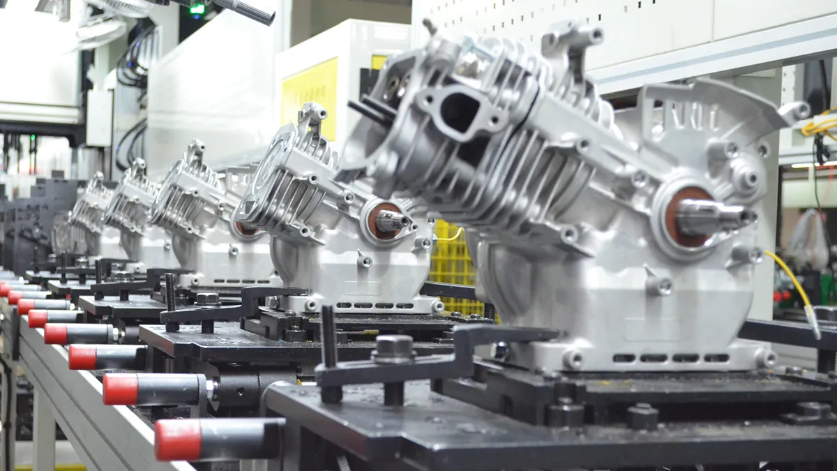
Water pump manufacturing involves a series of precise engineering, بالقطع, assembly, and testing processes. Every component—from the pump housing and impeller to the shaft, mechanical seal, and engine—must meet defined requirements before the complete unit can deliver stable flow and pressure in the field.
For gasoline and diesel water pumps used in irrigation, الصرف, بناء, and water transfer, manufacturing quality directly affects flow rate, يرفع, كفاءة الوقود, vibration, متانة, and operating reliability.
لذا, how are water pumps manufactured in a factory? The process typically covers engineering design, raw material selection, component machining, impeller manufacturing, pump and engine assembly, surface treatment, performance testing, final inspection, and packaging.
في هذا الدليل, we’ll walk through each stage of the water pump manufacturing process and explain the key quality controls used to produce reliable equipment for distributors, المستوردين, والمستخدمين المحترفين.
What Are Water Pumps Made Of?
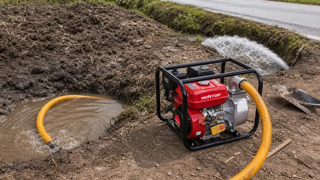
Water pump materials range from cost-effective cast iron to specialized alloys and engineered plastics, selected strictly based on fluid chemistry, system pressure, and abrasive wear conditions.
Primary Metals Used in Pump Housings and Impellers
Metal components form the main structural and hydraulic parts of most gasoline and diesel water pumps. Manufacturers select materials according to the required strength, وزن, مقاومة التآكل, وبيئة التشغيل.
- الحديد الزهر: Commonly used for pump housings and impellers where strength, متانة, and wear resistance are important. It is especially suitable for heavy-duty water transfer applications.
- Aluminum alloy: Widely used for portable water pump housings because it provides a good balance between strength and low weight. Reducing housing weight makes the complete pump easier to transport and handle.
- الفولاذ المقاوم للصدأ: Used for shafts, fasteners, and selected hydraulic components where higher corrosion resistance is required.
- Carbon steel and alloy steel: Common choices for shafts and other load-bearing components because they provide the strength needed for continuous rotation and mechanical loads.
For portable gasoline water pumps, material selection often involves balancing durability with portability. A cast-iron component may provide excellent wear resistance, while an aluminum housing can help reduce the total weight of the machine. على سبيل المثال, نيوتوب NTWP30 uses a cast-iron impeller and aluminum pump body, combining a durable rotating component with a relatively lightweight housing.
Non-Metallic Components and Sealing Materials
Metal components provide structural support, but non-metallic parts are equally important for reliable pump operation. الأختام, الحشيات, حلقات O, and other polymer components help prevent water leakage and protect internal parts.
Common materials include:
- Ceramic and carbon: Frequently used as mechanical seal faces because they provide good wear resistance and sealing performance.
- Nitrile rubber (NBR): Commonly used for seals and O-rings in general water pump applications.
- EPDM: Offers good resistance to water, heat, and weathering and can be used in suitable sealing applications.
- PTFE: Provides strong chemical resistance and low friction, making it useful for specific sealing requirements.
The correct sealing material depends on the water temperature, fluid characteristics, shaft speed, وظروف التشغيل. A high-quality mechanical seal is particularly important because leakage around the rotating shaft can quickly affect pump performance.
9 Steps of the Water Pump Manufacturing Process
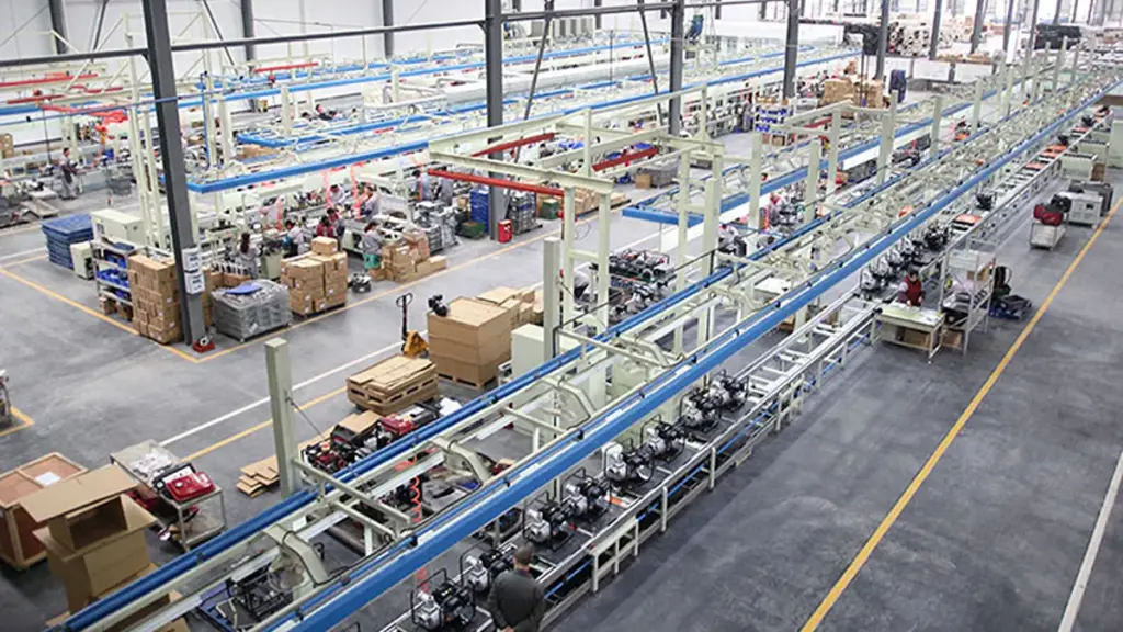
| Manufacturing Phase | Key Components Involved | Critical ضبط الجودة يفحص |
|---|---|---|
| Engineering & Forming | Casing, Volute, Core Shafts | Material composition and draft geometry |
| Machining & Preparation | Housings, Shaft seats, الدفاعات | CNC dimensional accuracy and static balance |
| Assembly & Sealing | Bearings, Mechanical seals, Motor | Fastener torque and shaft alignment |
| اختبار & Dispatch | Fully assembled pump unit | Hydraulic load testing and leak detection |
Step 1: Water Pump Design and Engineering
Engineers initiate the manufacturing cycle using advanced CAD software to establish the pump’s core geometry and performance targets. This digital blueprint dictates the physical architecture and maps out major part interfaces, which directly guides the downstream casting and machining operations.
Design teams calculate and account for critical operational variables from the start:
- Flow rate and head: Setting the baseline for hydraulic capacity.
- Fluid type: Adjusting for viscosity, corrosiveness, or abrasive solid content.
- Operating environment: Factoring in extreme ambient temperatures or submerged conditions.
Step 2: Raw Material Selection and Component Manufacturing
Factories select industrial-grade metals like cast iron, aluminum, or stainless steel based on the specific tensile strength and corrosion resistance the application demands. Foundries then form the major structural elements, including the pump body and volute, through heavy casting, forging, or smelting.
Simultaneously, specialized production lines manufacture the supporting internal mechanics. This includes:
- Drive shafts and rotors
- Stators and bearing assemblies
- Mechanical seals and gaskets
Step 3: Pump Body and Engine Component Machining
Rough castings rarely exit the mold ready for assembly. They undergo CNC precision machining to cut, drill, and face critical surfaces so they hit exact dimensional tolerances. This removes any casting flaws and guarantees a tight mechanical fit between mating parts.
Operators focus heavily on finishing essential structural points. Flawless machining is non-negotiable for housings, shaft seats, cover faces, and primary mounting surfaces to prevent future vibration or seal failure.
Step 4: Impeller and Internal Component Manufacturing
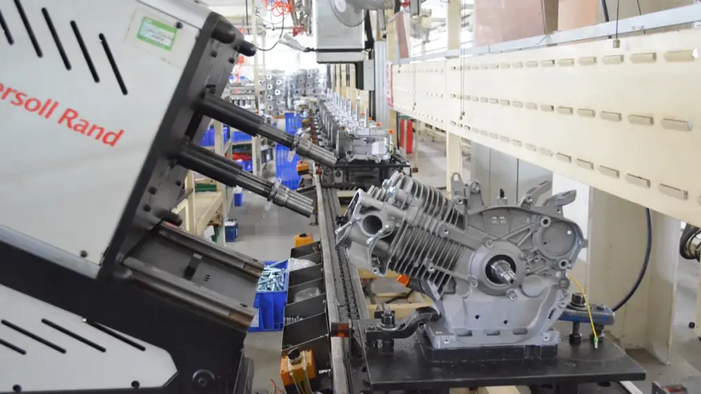
The impeller serves as the hydraulic heart of the pump. Technicians cast, machine, and precisely balance each impeller to eliminate erratic vibration and stabilize high-speed rotation. Engineers carefully optimize the impeller and diffuser geometry to maximize fluid pressure and flow output while minimizing mechanical strain.
Workers also prepare separate internal components prior to final assembly. They stage shaft pipes, balanced rotors, and wound stators so the production line maintains a steady workflow.
Step 5: Engine and Pump Assembly
Assembly lines merge the machined casing, balanced impeller, drive shaft, and prepared internals into a complete operational unit. For engine-driven configurations, technicians install and align the motor, securely fastening all heavy-duty drive components to prevent torque distortion.
This stage requires exact handling to avoid misalignment or pressure drops. Workers carefully press-fit bearings and install mechanical seals, lock nuts, and mating flanges to establish a reliable, leak-proof barrier.
Step 6: Surface Treatment and Finishing
Bare metal requires defense against harsh industrial or outdoor environments. Technicians apply specialized surface treatments like anti-rust paint, heavy powder coating, or protective enamel to shield the exterior from corrosion and physical wear.
Preparation goes beyond the exterior housing. Workers clean, dry, and apply specific pre-coats to internal cavities and bearing boxes to prevent internal degradation before the pump ever sees liquid.
Step 7: Water Pump Performance Testing
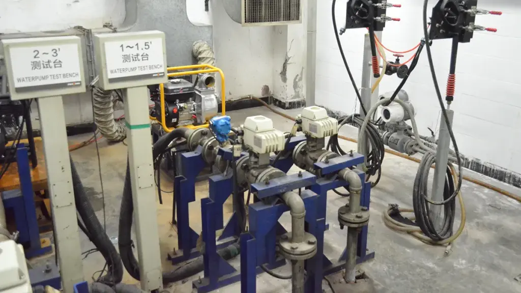
Performance testing acts as the primary proof of build quality. Technicians mount the fully assembled pump on a closed-loop hydraulic test bench and run it under load to verify it hits guaranteed operational standards.
Inspectors monitor and record these critical parameters:
- Hydraulic output: Checking exact flow rate and discharge pressure.
- Integrity: Scanning for housing leaks and seal weeping.
- ميكانيكا: Measuring operational noise and detecting abnormal vibration.
Step 8: Quality Control and Final Inspection
Final inspection serves as the last barrier before dispatch. Quality control teams conduct strict visual and dimensional checks, confirming the physical product aligns perfectly with the original engineering drawings. They also verify cleanliness to keep debris out of the internal fluid path.
Inspectors aggressively hunt for defects. They will catch and reject any units showing surface damage, pinhole leaks, poor shaft alignment, or uneven coating. They also validate batch tracking codes to maintain full manufacturing traceability.
Step 9: Packaging and Shipment
The factory floor cleans, labels, and securely packs the approved water pumps using impact-resistant protective materials. Proper packaging prevents transit damage during rough freight handling and long-distance hauling.
Logistics teams insert necessary accessory kits, user manuals, and final batch tracking documents into the crates. The packaged units are then dispatched to industrial users, regional distributors, or direct retail channels.
Maximize Margins With Premium Agricultural Machinery
How Does a Factory Ensure Water Pump Quality?
Factory quality assurance for water pumps is an integrated system. It combines strict incoming material checks, precision CNC machining, controlled assembly, and rigorous hydraulic testing before final shipment.
Engineering Design and Material Inspection
Quality control starts long before parts hit the production floor. Engineers use CAD and 3D modeling software to define exact pump geometry, tight tolerances, and strict performance targets. This upfront design dictates the required strength and corrosion resistance, leading to the selection of core materials like cast iron, aluminum, and stainless steel. Once the raw materials arrive, the factory conducts thorough incoming inspections. Technicians verify the chemical and physical properties of all metals, copper windings, rubber components, plastics, and seals to guarantee only approved materials enter the manufacturing line.
Casting, Molding, and Machining Controls
Structural integrity relies on highly controlled casting and molding processes. Foundries manage melting, pouring, and cooling times to prevent hidden defects like porosity or cracking in the rough casings. After casting, the components move to the machining phase. Operators use CNC machines, drills, and lathes to cut proper fits for bearings and shafts. The goal here is maintaining exact dimensional tolerances. This precision ensures correct impeller clearances, which directly prevents internal friction and maximizes hydraulic efficiency.
Motor Assembly and Verification
لمضخات المياه الكهربائية, mechanical and electrical reliability are inseparable. Technicians focus heavily on copper winding density, precise rotor balancing, and thorough insulation resistance checks before motor integration. On the assembly line, workers install pump housings, الأختام, محامل, and fasteners following strict fit-up and torque control protocols. Factories set up dedicated inspection points throughout this sequence. These checks verify component alignment at every stage, preventing hidden assembly defects from moving down the line and reaching the customer.
Comprehensive Performance Testing
Performance testing acts as the primary proof of build quality. Finished units undergo rigorous evaluations on closed-loop test benches to validate their operational metrics against the original engineering targets.
- Hydraulic Performance: Technicians confirm the pump delivers the exact head, flow rate, and power consumption required by the specification.
- Pressure and Leakage: Hydrostatic tests check the casing integrity and mechanical seal effectiveness under heavy load.
- Noise and Vibration: Monitoring equipment detects abnormal running behavior caused by rotor imbalance or internal misalignment.
Final Inspection and Traceability
The last quality gate happens right before the pump leaves the factory. Quality control teams conduct final visual inspections to check surface cleanliness, correct labeling, and accurate documentation. They also verify packaging standards to reduce the risk of transit damage. Factories log every unit with batch tracking and inspection data. If a field defect occurs, the manufacturer can quickly isolate the specific production lot. This traceability extends into after-sales support, where factories analyze field performance data to refine future testing standards and engineering designs.
Looking for a Reliable Water Pump Manufacturer? Talk to NEWTOP
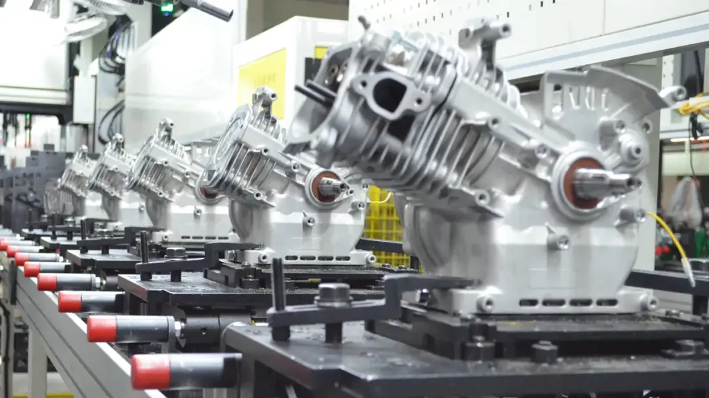
Choosing a water pump supplier means looking beyond flow rate and engine power. Consistent quality, أداء موثوق, and stable production are equally important for long-term business.
نيوتوب manufactures gasoline and diesel water pumps for irrigation, الصرف, بناء, and general water transfer. With different flow, رأس, and port configurations, NEWTOP can provide suitable solutions for different applications and market requirements.
If you are sourcing water pumps for wholesale, توزيع, or OEM/ODM projects, talk to NEWTOP about your required specifications and order volume. Our team can help you select the right pump for your market and application.
Need a reliable water pump supplier? اتصل بـ NEWTOP اليوم.
الأسئلة المتداولة
What materials are best for water pump housings?
The choice depends on the application. Cast iron and ductile iron are standard for general-purpose pumps due to strength and cost-efficiency. Stainless steel and bronze are preferred for corrosive or marine environments, while engineering plastics like PVDF handle highly chemical-laden water.
How is ISO 9906 used in water pump manufacturing?
ايزو 9906 is an international testing standard for rotodynamic pumps. Factories use it during final acceptance testing to verify that a pump meets the buyer’s guaranteed flow, الرأس الإجمالي, and power specifications within standardized tolerance grades before it leaves the facility.
What methods do factories use to test for pump leakage?
Manufacturers primarily rely on hydrostatic pressure tests, where the assembled pump is filled with water and pressurized to 1.5 times its rated working pressure. Technicians hold this pressure for several minutes to verify that the casing, joints, and mechanical seals remain completely water-tight.
How do manufacturers test the flow and pressure of a new pump?
Pumps are installed on a calibrated closed-loop test bench and run at various operating speeds. Flowmeters and pressure transducers measure the discharge flow and head at multiple duty points. This data creates a performance curve that is compared against the factory guarantee.
What final quality checks occur before a water pump is shipped?
Before dispatch, pumps undergo a rigorous end-of-line inspection. This includes visual and dimensional checks, functional performance runs, electrical safety tests for motorized units, acoustic checks for abnormal vibration, and a final verification of packaging and labeling integrity.

China is one of the world’s major manufacturing bases for portable diesel water pumps, with suppliers ranging from specialized pump factories to outdoor power equipment manufacturers offering engines, مولدات, الرشاشات, and pumps.
For importers, الموزعين, agricultural equipment dealers, والمشترين OEM, the challenge is not simply finding a factory with a diesel water pump. The more important questions are whether the manufacturer can provide stable quality, suitable flow and head performance, reliable spare parts, export certifications, consistent production, and long-term technical support.
Based on product range, manufacturing experience, production capabilities, export focus, and publicly available product information, the following are 10 China portable water pump manufacturers worth considering in 2026.
قمة 10 مصنعي مضخات المياه المحمولة بالديزل في الصين
Quick Comparison Overview
| الشركة المصنعة | موقع | Main Strength | Diesel Water Pump Focus | Suitable For |
|---|---|---|---|---|
| نيوتوب | الصين | Outdoor power equipment & تصنيع المعدات الأصلية | Portable diesel pumps, high-flow models | المستوردين, الموزعين, تصنيع المعدات الأصلية |
| BISON | Taizhou, تشجيانغ | Power equipment | Diesel, high-pressure and cast-iron pumps | Wholesale & الموزعين |
| Taizhou Genour Power Machinery | Taizhou, تشجيانغ | Engines, مولدات & مضخات | Diesel and gasoline water pumps | Global dealers |
| Taizhou Newland Machinery | Taizhou, تشجيانغ | High-volume pump production | Diesel water pumps | Wholesale buyers |
| Taizhou Yuhao Machinery | Taizhou, تشجيانغ | Power equipment | Diesel pumps and engines | المستوردين & الموزعين |
| Taizhou Longfa Machinery | Taizhou, تشجيانغ | مولدات, المحركات & مضخات | 2", 3", 4" and high-pressure pumps | زراعة & outdoor use |
| Zhejiang Leo Garden Machinery | Wenling, تشجيانغ | Garden machinery | Diesel and gasoline pumps | حديقة & agricultural channels |
| Zhejiang Wenxin | تشجيانغ | Agricultural equipment | Diesel and gasoline pumps | زراعة & sprayer dealers |
| Fuan Ocean Motor | Fu’an, Fujian | Motors & مضخات | Diesel engine and high-pressure pumps | Pump distributors |
| Fuan Sea Pump | Fu’an, Fujian | Pumps and power equipment | Diesel and fuel-engine pumps | Export wholesalers |
#1 نيوتوب
NEWTOP stands out as a high-volume global supplier by delivering premium component-backed diesel pumps and extensive OEM customization for emerging markets.
تأسست في 2003, نيوتوب is an outdoor power equipment manufacturer with a 10,000 m² factory and annual production capacity of 500,000+ وحدات. Its product range includes مناشير, قواطع الفرشاة, الرشاشات, مولدات, tillers, المحركات الخارجية, و مضخات المياه.
ال NTDWP30 is a 3-inch diesel water pump powered by a 4 kW NTDE178F engine, delivering up to 60 m³/h flow, 26 m head, و 8 m suction height.
وتشمل المزايا الرئيسية:
- OEM/ODM support for branding, colors, التعبئة والتغليف, and specifications
- 500,000+ units annual capacity for stable bulk supply
- 26 الشهادات supporting international market requirements
- الشهادات include م, ECE, وكالة حماية البيئة, اليورو الخامس, ايزو 9001, and ISO 14001
- Multiple pump options, مشتمل ديزل, gasoline, high-pressure, and cast-iron models
For importers and distributors seeking a reliable portable diesel water pump manufacturer with broader outdoor power equipment capabilities, NEWTOP is worth considering.
📊 At a Glance:
- 📍 Location: شنغهاي, الصين
- 🏭 Core Strength: Diesel Water Pumps, مناشير, قواطع الفرشاة, مولدات
- 🌍 Key Markets: أفريقيا, أمريكا اللاتينية, آسيا, أوروبا الشرقية
Why We Picked Them:
| ✅ The Wins | ⚠️ Trade-offs |
|---|---|
|
|
#2 BISON
BISON excels by offering export-ready, mid-market portable pumps alongside a diverse equipment portfolio for simple one-stop sourcing.
BISON operates out of Taizhou, manufacturing a wide array of diesel water pumps and power equipment. They supply a broad range of portable, mid-market pumps spanning 2-inch to 4-inch sizes, complete with convenient electric-start options.
The company focuses heavily on factory-direct wholesale, targeting farm irrigation, emergency transfer, and utility applications. Buyers benefit from their strong focus on providing export-ready documentation to simplify global logistics.
📊 At a Glance:
- 📍 Location: Taizhou, تشجيانغ, الصين
- 🏭 Core Strength: Diesel Water Pumps, مولدات, Engines, Pressure Washers
- 🌍 Key Markets: عالمي
#3 Taizhou Genour Power Machinery

Genour excels at delivering compact, export-ready diesel pumps tailored for wholesale distribution and commercial irrigation.
Specializing in engine and water pump manufacturing for over 10 سنين, Genour offers portable diesel water pumps in 1-inch to 4-inch variants under the PowerValue brand.
They are highly active in wholesale and distribution channels, focusing on compact diesel units for commercial irrigation and construction site dewatering.
📊 At a Glance:
- 📍 Location: Taizhou, تشجيانغ, الصين
- 🏭 Core Strength: Gasoline/Diesel Engines, مولدات, مضخات المياه المحمولة
- 🌍 Key Markets: عالمي
#4 Taizhou Newland Machinery

Newland excels at providing EU-compliant diesel pumps alongside a diverse equipment catalog to simplify mixed-container sourcing.
Newland manufactures multi-category equipment, supplying portable centrifugal diesel pumps like their 4-inch 10hp models.
Operating from the Taizhou manufacturing hub, the company supplies European and international markets by maintaining strict EU Stage V and CE compliance.
📊 At a Glance:
- 📍 Location: Taizhou, تشجيانغ, الصين
- 🏭 Core Strength: Diesel Water Pumps, مولدات, Air Compressors
- 🌍 Key Markets: عالمي
#5 Taizhou Yuhao Machinery
Yuhao Machinery excels in providing competitive pricing and flexible OEM options for bulk agricultural pump procurement.
Yuhao Machinery operates as a mid-market supplier within the Taizhou manufacturing ecosystem, focusing on portable diesel water pumps and related power equipment.
They supply irrigation and emergency dewatering pumps at competitive price points, specifically targeting B2B bulk procurement and OEM supply for the agricultural sector.
📊 At a Glance:
- 📍 Location: Taizhou, تشجيانغ, الصين
- 🏭 Core Strength: Diesel Water Pumps, Agricultural Pumping Equipment
- 🌍 Key Markets: عالمي
#6 Taizhou Longfa Machinery
Longfa Machinery stands out for its high-volume production capacity of 15,000 units per month, making them an excellent fit for bulk wholesalers.
Established in 2003, Longfa Machinery manufactures portable and high-pressure diesel water pumps alongside industrial generators. They supply the agricultural and construction sectors with reliable, movable 4-inch, 10HP pumping configurations.
The factory operates with a robust output capability designed to support fast-moving supply chains. This capacity allows them to service large distributors who need consistent, high-volume equipment shipments without production bottlenecks.
📊 At a Glance:
- 📍 Location: Taizhou, تشجيانغ, الصين
- 🏭 Core Strength: Portable Diesel Water Pumps, مولدات, Power Engine Sprayers
- 🌍 Key Markets: عالمي
#7 Zhejiang Leo Garden Machinery
Operating under a major corporate umbrella, they excel in providing highly reliable, fully certified pumps validated by a state-authorized testing laboratory.
As part of the extensive Leo Group, this Wenling-based manufacturer builds robust diesel and gasoline engine pumps. A CNAS-recognized laboratory and rigorous quality control systems back their entire production line.
They supply fully CE-compliant portable pumps engineered for demanding agricultural and industrial water-transfer tasks. This infrastructure guarantees consistent performance for buyers scaling up their equipment sourcing.
📊 At a Glance:
- 📍 Location: Wenling, تشجيانغ, الصين
- 🏭 Core Strength: Diesel Engine Pumps, Gasoline Water Pumps, Submersible Pumps
- 🌍 Key Markets: عالمي
#8 Zhejiang Wenxin Electrical and Mechanical Manufacturing
Wenxin stands out as a reliable regional partner, offering highly competitive pricing through their deep integration into the local supply chain.
Operating in the dense Zhejiang pump ecosystem, Wenxin manufactures standard portable diesel water pumps.
The company supplies mobile diesel pump sets for agricultural, البلدية, and industrial water-transfer applications. This focus makes them an excellent fit for project-based sales and B2B wholesale buyers.
📊 At a Glance:
- 📍 Location: تشجيانغ, الصين
- 🏭 Core Strength: Diesel Portable Water Pumps, Mechanical Equipment
- 🌍 Key Markets: عالمي
#9 Fuan Ocean Motor
Fuan Ocean Motor excels by delivering specialized high-pressure diesel pumps built for demanding irrigation and fire-support operations.
Based in the Fuan region of Fujian, Ocean Motor exports globally under the CEAN brand. They specialize in engineering high-flow and high-pressure portable diesel water pumps.
These compact, durable models routinely serve heavy-duty farm irrigation and portable fire-support scenarios. Buyers benefit from verified quality standards backed by ISO9001 and CE certifications.
📊 At a Glance:
- 📍 Location: Fuan, Fujian, الصين
- 🏭 Core Strength: Diesel Water Pumps, Electric Motors, Solar Pumps
- 🌍 Key Markets: عالمي
#10 Fuan Sea Pump

Fuan Sea Pump excels by offering premium Cummins OEM engine integration alongside top-tier international export certifications.
Fuan Sea Pump operates as a Fujian-based manufacturer and an official Cummins OEM partner. They engineer robust engine-driven water pump systems optimized specifically for construction dewatering and emergency fluid transfer tasks.
The company holds stringent CE, ع, and TUV certificates. This strict compliance profile makes their heavy-duty equipment highly viable for buyers navigating tightly regulated international markets.
📊 At a Glance:
- 📍 Location: Fuan, Fujian, الصين
- 🏭 Core Strength: مضخات المياه, Engine-Pump Systems
- 🌍 Key Markets: عالمي
How to Choose the Right Diesel Water Pump Manufacturer in China
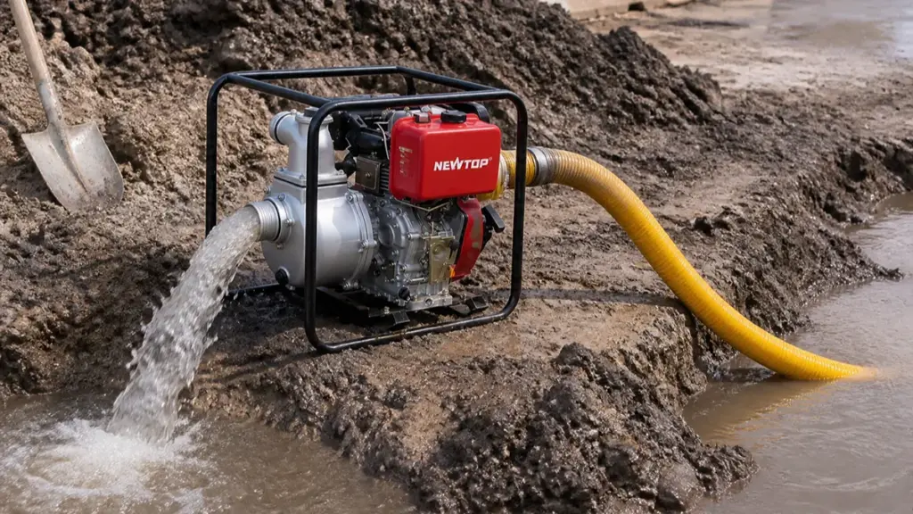
A portable diesel water pump is a complete system in which the engine, pump body, impeller, shaft, الأختام, frame, fuel system, and starting system all affect long-term performance.
Start with the application. Agricultural irrigation, flood drainage, construction dewatering, دعم مكافحة الحرائق, and general water transfer may require very different flow and head characteristics.
Then compare these technical points:
- معدل التدفق: Determine how many cubic meters per hour you actually need.
- Total head: Consider vertical lift plus pipe friction and system resistance.
- Suction height: Check the maximum practical suction distance from the water source.
- Engine power: Do not select horsepower alone; match engine output to the pump curve.
- Pump material: Cast iron is common for demanding applications, while other materials may be preferred for weight or corrosion considerations.
- Starting system: Recoil starting may suit basic portable models, while electric start can improve convenience on larger units.
- Spare parts: Confirm availability of seals, الدفاعات, carburetion/fuel components, المرشحات, and engine parts.
- Certification: Request certificates for the exact model and target market.
- OEM capability: Confirm whether the supplier can support your logo, colors, التعبئة والتغليف, كتيبات, and product specifications.
A reliable portable water pump supplier should also provide a clear datasheet and explain the difference between maximum flow and working flow. Maximum flow is normally measured under very low resistance, while real-world performance decreases as head and pipe resistance increase.
الأفكار النهائية
For distributors and importers looking for a complete outdoor power equipment supply partner, NEWTOP combines diesel water pumps with a wider range of outdoor power equipment and OEM support, making it possible to build a broader product portfolio through one long-term manufacturing relationship.
Need a reliable diesel water pump for your market? Contact NEWTOP to discuss specifications, OEM requirements, موك, and wholesale pricing.
الأسئلة المتداولة
How do I verify a water pump factory in China?
Ask for the business license, factory address, production photos or video, product catalog, quality certificates, testing records, and recent export references. A live factory video call or third-party factory audit provides stronger evidence than a supplier profile alone.
What certifications should a diesel water pump supplier have?
Common requirements may include CE, ايزو 9001, وكالة حماية البيئة, EMC, ع, or market-specific environmental and safety compliance. Requirements vary by destination. Always confirm the certificate number, issuing organization, validity, and exact product model before ordering.
Can Chinese manufacturers make OEM water pumps?
نعم. Many Chinese manufacturers support OEM and private-label water pumps, including custom logos, colors, التعبئة والتغليف, كتيبات, and selected specifications. نيوتوب also welcomes qualified overseas distributors and agents, offering OEM water pumps and a wider range of outdoor power equipment for long-term market cooperation.
What is the typical MOQ for portable diesel water pumps?
There is no single standard MOQ. It depends on the manufacturer, model, التعبئة والتغليف, OEM requirements, and whether the order uses an existing product configuration. Buyers should request the MOQ for both standard orders and private-label orders separately.
How do I inspect a water pump factory before ordering?
Check raw-material control, engine and pump assembly, بالقطع, testing equipment, finished-product inspection, warehouse management, التعبئة والتغليف, spare-parts storage, and production records. For larger orders, an independent factory audit can provide additional assurance.
What pump tests should I request from a supplier?
Request performance testing for flow rate, الرأس الإجمالي, suction height, starting performance, continuous running, fuel consumption, vibration, noise, تسرب, and engine stability. For an OEM order, it is also useful to approve a pre-production sample and define the acceptance criteria before mass production.
