


- All
- NEWTOP Customer Stories
- NEWTOP Explorer Hub
- NEWTOP Industry Insights
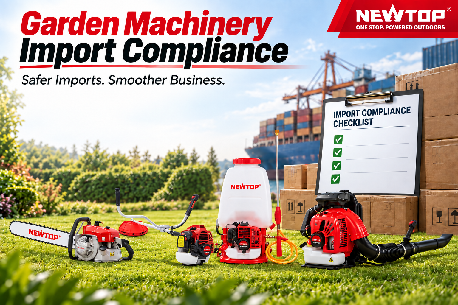
Working with the right outdoor power equipment supplier is only one part of an international machinery order. The same brush cutter, chainsaw, lawn mower, generator or water pump can leave the factory with the same basic specification but face a different import process depending on whether it is headed for Nigeria, Tanzania, Brazil or Mexico.
The trouble usually starts when compliance is checked too late. A shipment may require conformity verification before export. An electric model may fall under rules that do not apply to its gasoline-powered equivalent. Labels, technical files, or importer information may also need to change before production is completed.
For distributors, the useful question is therefore not simply:
“Which certificate does this machine have?”
It is:
“What does this specific product need in the country where I plan to sell it?”
This guide focuses on practical import checks for major African and Latin American markets relevant to garden machinery and outdoor power equipment. It is intended to help importers know what to confirm with their supplier before an order moves into production.
Compliance note: Requirements can change and often depend on the exact HS code, product type, engine or electrical configuration, and intended use. Final import requirements should always be confirmed with the local importer, customs broker, conformity-assessment body, or competent authority.
Start With the Product, Not With a Certificate
There is rarely one certificate that answers every import question.
A CE document may support a technical file but does not automatically replace the local conformity route in another country. South Africa, for example, expressly states that CE certificates alone are not accepted for products requiring NRCS approval; accredited safety test reports are required instead.
Before asking a supplier for documents, separate the main compliance questions:
| Compliance Area | What Needs to Be Confirmed |
|---|---|
| Customs Classification | Correct HS, NCM, tariff fraction, or national tariff code |
| Product Conformity | Whether the product falls under compulsory standards or certification |
| Engine / Emission Rules | Requirements applying to gasoline or diesel engines |
| Electrical Requirements | Safety, EMC, voltage, frequency, plugs, chargers, or electrical components |
| Labeling | Language, importer details, safety information, ratings, and local markings |
| Pre-Shipment Verification | Whether conformity needs to be checked before export |
| Import Documents | Invoice, packing list, certificate of origin, bill of lading, test reports, and permits |
The correct order is usually:
identify the product → confirm the tariff classification → check the applicable regulation → prepare the required product and shipment documents.
Starting with “we already have CE” and trying to work backwards is far less reliable.

Importing Garden Machinery into Africa
Africa is not one regulatory market. Nigeria, Kenya, Tanzania, Zambia, Ghana and South Africa all approach imported equipment differently.
For Chinese exporters in particular, Kenya and Tanzania also deserve early attention because conformity work may take place before the goods leave China.
Nigeria: SONCAP Needs to Be Checked Early
Nigeria’s SONCAP system applies to SON-regulated imported products and operates as an offshore, pre-shipment conformity-assessment programme.
For regulated goods, the process can involve a Product Certificate, testing and verification in the exporting country, a Certificate of Conformity, and ultimately the SONCAP Certificate used for customs clearance. SON states that Product Certificates are used in the Form M process, while the SONCAP Certificate is required for customs clearance of regulated goods.
That makes Nigeria a poor market for leaving compliance until the container is ready.
Before confirming a commercial order, the importer should establish:
- whether the actual product is within SONCAP scope;
- which applicable standard and certification route will be used;
- what documents the exporter needs to prepare;
- whether inspection or testing will be required before shipment.
A distributor importing finished chainsaws, brush cutters, generators, or other machinery for resale should also avoid assuming that an exemption intended for industrial machinery imported for a manufacturer’s own use applies to normal commercial stock.
The exact product and intended import route matter.
Ghana: Mandatory Standards and EasyPASS Are Not the Same Thing
Ghana is worth treating carefully because EasyPASS attracted considerable attention in 2026.
In July 2026, the Ghana Standards Authority clarified that EasyPASS did not introduce a new compulsory requirement for every importer. It is an established conformity-assessment programme. At the same time, GSA emphasized that products placed on the Ghanaian market must still comply with applicable mandatory Ghana Standards, regardless of whether the business participates in EasyPASS.
So the first question should not be “Do I need EasyPASS?”
It should be:
Is this particular machine covered by a mandatory Ghana Standard, and what conformity route applies to it?
For customs clearance, Ghana Revenue Authority currently lists documents such as the Bill of Lading or waybill, invoice, packing list, Import Declaration Form, importer identification, and any permit required by the relevant regulator.
For the exporter, consistency matters. The model description on the invoice, packing list, technical documents, labels and physical machine should tell the same story.
Kenya: PVoC Can Put the Inspection Before the Shipment
Kenya operates a Pre-Export Verification of Conformity programme through KEBS.
The current KEBS guidance states that PVoC is carried out in the exporting country to verify compliance with applicable Kenyan technical regulations, mandatory standards, or approved specifications. China is included among the exporting zones served by KEBS-appointed PVoC contractors.
For an outdoor equipment order, that can move part of the compliance work forward in the purchasing timeline.
Instead of waiting for cargo to arrive in Kenya, the importer and supplier may need to coordinate product information, supporting test reports, physical inspection, and certification while the goods are still in the country of export.
A practical sequence is:
Product scope → applicable Kenyan standard → PVoC request → inspection/testing if required → CoC → shipment
Not every import uses the same route, and KEBS publishes exemptions for certain goods and users. A commercial distributor should therefore confirm the actual treatment rather than assume an exemption applies.
Tanzania: For Regulated Goods, the CoC Is Part of the Shipping Plan
Tanzania also operates a PVoC system, and the current TBS programme covers regulated products before export.
TBS’s 2025 PVoC guideline states that affected consignments are inspected and/or tested before shipment and require a Certificate of Conformity. Its current import-control page also maintains lists of regulated HS codes and PVoC procedures.
This is particularly relevant to NEWTOP because TBS issued a June 2026 notice specifically reminding importers of regulated goods originating from China Mainland and several nearby territories that PVoC inspection must take place in the country of export before shipment.
For a Tanzanian buyer, the supplier therefore needs more than a generic PDF test report. The important issue is whether the product information and available conformity evidence are suitable for the actual TBS route.
TBS’s summarized procedure indicates that documentary review can include technical product details, third-party conformity evidence, accredited laboratory reports, and control testing where necessary.
Zambia: Check Whether the Product Is Actually Under a Compulsory Standard
Zambia takes a more product-specific approach.
The Zambia Compulsory Standards Agency currently administers import quality monitoring for goods covered by compulsory standards. Its published information states that the system applies specifically to regulated products rather than every imported item.
This distinction is useful for garden machinery.
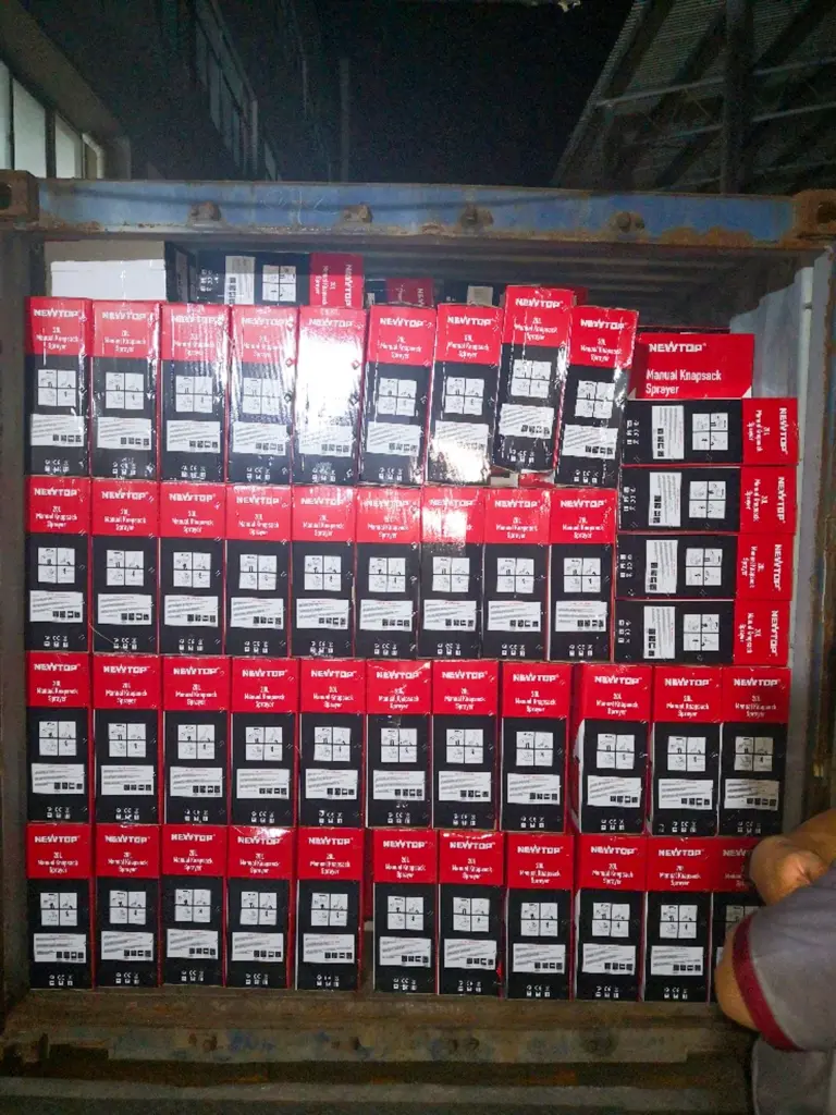
A gasoline machine, an electrical tool, a battery-related product, and an accessory should not automatically be treated as one compliance category.
Before asking a supplier to obtain a particular certificate, the importer should first compare the product against the current ZCSA compulsory-standard scope.
ZCSA also provides several import-clearance arrangements, including batch clearance, pre-import schemes, and annual import quality certification for qualifying importers.
In other words, the compliance conversation becomes more efficient when the buyer starts with the exact product rather than a generic request for “Zambia certification.”
South Africa: Battery-Powered Garden Equipment Deserves a Separate Check
South Africa is one of the markets where gasoline-powered and battery-powered garden equipment should not automatically be treated under the same compliance route.
The NRCS regulates certain electrical and electronic products under compulsory specifications. Its current list includes VC 9105 for electric motor-operated hand-held tools, transportable tools, and lawn and garden machinery. Battery-powered garden equipment may therefore require a separate regulatory check even though the machine itself is not connected directly to mains power.
Where a product falls within the applicable compulsory specification, the relevant model or product family may require regulatory approval before entering the South African market. The applicant must be a South African legal entity, and accredited test reports can form part of the approval evidence.
The charger should also be reviewed separately, as its rated voltage, plug configuration, electrical safety, and other requirements may fall under additional South African electrical regulations.
NRCS is also clear on one point:
A CE certificate on its own is not accepted as the regulatory approval basis.
This does not mean gasoline-powered chainsaws, sprayers, or brush cutters automatically follow the same approval route.
For distributors carrying both gasoline and lithium battery-powered outdoor equipment, each product type should be checked against the applicable NRCS scope rather than using one compliance file across the entire range.
Importing Garden Machinery into Latin America
Latin America often looks different from the African PVoC markets.
Rather than one broad pre-export programme, compliance frequently begins with the tariff classification and then moves into product-specific technical regulations, electrical requirements, labeling, or import authorizations.
That makes the exact product description particularly important.
Brazil: Start With the NCM, Not With “Do You Have Inmetro?”
Brazilian importers should begin with the NCM classification.
Inmetro’s latest guidance, updated in August 2026, tells importers to use the NCM code in Portal Único Siscomex to check the applicable administrative treatment and determine whether Inmetro approval is required.
This matters because an NCM falling within a controlled area does not automatically mean every product classified there follows the same certification requirement. Inmetro also provides exclusions and exemption routes where the specific product falls outside regulatory scope.
Start with: Correct NCM classification
Check next: Administrative treatment in Portal Único Siscomex
If applicable: Confirm whether Inmetro certification, registration, or import approval is required
Prepare before ordering: Exact model, technical description, power source, voltage/frequency where applicable, manufacturer details, and supporting test documentation
For the supplier, this means the final model information cannot be vague.
Inmetro’s import guidance specifically calls for clear product descriptions containing information such as brand, model or part number, technical characteristics, power, voltage, operating range, and application where relevant.
A gasoline lawn mower, an electric pressure washer, and a battery charger may therefore follow different compliance routes even though one distributor buys all three from the same factory.
Mexico: Match the Tariff Fraction to the Applicable NOM
Mexico also works better when the importer begins with classification rather than with a certificate name.
SNICE maintains an Annex of tariff fractions subject to compliance with Mexican Official Standards at import. The applicable NOM therefore needs to be checked against the actual tariff fraction and product scope.
For an importer, the workflow is more useful when expressed this way:
Tariff fraction → Applicable NOM → Conformity / labeling requirements → Final Spanish product information and packaging
Electrical equipment needs particular care because electrical-safety requirements may involve different standards from gasoline-powered equipment.
The importer should therefore finalize the correct model, electrical configuration, ratings, and labeling requirements before artwork and packaging are approved.
It is much easier to print the right Spanish label at the factory than to correct thousands of boxes after customs or market-surveillance questions arise.
Colombia: Check the Technical Regulation Before Commercialization
Colombia applies technical regulations by product rather than by the broad description “garden machinery.”
The Superintendencia de Industria y Comercio states that products subject to technical regulations must comply with the applicable regulation before commercialization and may require the appropriate conformity certificate. Manufacturers and importers of goods covered by SIC-supervised technical regulations are also subject to registration requirements.
Electrical products require another layer of attention.
Colombia updated its RETIE framework through Resolution 40284 of June 23, 2026. The current regulation contains separate sections dealing with products within scope and conformity assessment.
That does not mean every electric lawn mower or charger automatically falls under RETIE in the same way.
The importer needs to check the exact product against the current scope.
For mixed petrol and electric ranges, one regulatory answer should therefore never be copied across every SKU without verification.
Chile: Check SEC Scope for Electrical and Fuel-Related Products
Chile operates compulsory certification systems through the Superintendencia de Electricidad y Combustibles for specified electrical and fuel products.
SEC states that products falling within the mandatory system must be certified before commercialization and carry the applicable certification marking. It also provides different conformity routes, including mechanisms involving recognized foreign certification in eligible cases.
For a garden-machinery importer, the first job is to confirm whether the exact product appears within SEC’s regulated scope.
If it does, certification, testing, labels, and supporting product information should be planned before shipment.
If it does not, the importer should not request a random “SEC certificate” simply because another electrical product needed one.
The scope of the regulation remains the deciding factor.
Peru: Use the Tariff Subheading to Find the Restriction
Peru makes this process fairly easy to understand conceptually.
SUNAT advises importers to use the national tariff subheading to identify whether goods are subject to restrictions and which government authority issues the relevant control document. Restricted goods require the appropriate authorization in addition to normal customs documents.
For many regulated procedures, Peru’s VUCE acts as the electronic trade window.
So instead of starting with assumptions based on another Latin American country, the buyer can work through:
Peruvian tariff subheading → restriction check → competent authority → required document
This is particularly useful when a distributor carries several equipment categories.
A gasoline engine product, electric machine, accessory, or battery-related product may not all produce the same result.
Venezuela: Verify the Current Tariff Treatment Before Production Is Finished
Venezuela deserves more caution because its customs tariff has undergone repeated amendments, including further changes during 2026. Current tariff treatment should therefore be checked against the exact product code at the time of the import.
Under the Venezuelan customs framework, Legal Regime 20 is linked to goods affected by mandatory COVENIN standards or technical regulations, with SENCAMER involved in determining applicability. However, this should not be interpreted as meaning every chainsaw, mower, brush cutter, generator, or pump automatically follows that procedure.
Do not assume that every garden machine follows the same SENCAMER procedure. The local importer or customs representative should verify the current tariff code, applicable legal regime, and any COVENIN or technical-regulation requirement before labels, packaging, and shipment are finalized.
This is especially important where customized labels or importer information are involved.
The local check should happen before the supplier finishes artwork and production—not after the goods are already on the water.
Gasoline and Battery-Powered Equipment Need Different Compliance Checks
Product type can change the regulatory discussion even within the same country.
For conventional gasoline-powered equipment, the buyer may need to consider engine specifications, emissions documentation, safety information, noise requirements, and fuel-system characteristics where relevant.
NEWTOP also offers lithium battery-powered outdoor equipment. These products should be reviewed separately because lithium batteries can introduce additional safety, transportation, testing, documentation, and destination-market requirements. The charger may also bring its own electrical requirements, including rated voltage, frequency, plug configuration, electrical safety, and EMC, depending on the market.
For that reason, a compliance file confirmed for a gasoline brush cutter should never be assumed to cover a lithium battery-powered model simply because the two products serve the same application.
What the Outdoor Power Equipment Supplier Can Prepare
The local importer remains responsible for confirming the final regulatory route, but the supplier plays an important role long before the customs declaration is filed.
When a buyer provides clear destination-market requirements, NEWTOP can review the product configuration and prepare supporting information before the order is finalized.
Typical export documents available can include:
- Commercial Invoice
- Packing List
- Certificate of Origin
- Bill of Lading
- Product manuals
- Test reports
- Other agreed product or shipment documentation
Depending on the product and model, NEWTOP also has documentation or certifications including CE, EMC, EPA, RoHS and EURO V. Marine products can involve additional certification such as CCS.
These should not be presented as a single certificate package covering every NEWTOP product.
The right approach is to match the available document to the actual model, destination, and import requirement.
Labels and Packaging Can Be Prepared for the Market
A supplier can also prevent problems by getting market-specific product information right during production.
Voltage and frequency must always reflect the machine’s actual technical configuration. They should not be altered simply because a customer requests different numbers on the label.
Other elements can be customized according to confirmed importer requirements, including:
- language;
- importer information;
- warning labels;
- product and carton labels;
- logos;
- packaging artwork;
- barcodes and other commercial information.
For NEWTOP distributors and appointed agents, these market-specific requirements can be discussed before production so that the finished goods arrive with the agreed branding and information already in place.
That is considerably more efficient than relabeling inventory after it reaches the destination.
A Pre-Shipment Compliance Review Saves More Than a Port-Side Fix
Before production is released or the container is booked, the importer and supplier should make sure they are working from the same final compliance information.
The useful questions are straightforward:
- What is the final HS, NCM, or national tariff code?
- Is the product covered by a compulsory technical regulation?
- Does it require PVoC, certification, registration, or another approval?
- Is the final engine or electrical configuration the same one used in the technical documents?
- Are voltage and frequency correct?
- Has the required label language been confirmed?
- Does the market require importer information on the product or package?
- Which test reports or certificates are available for the actual model?
- Do the invoice and packing-list descriptions match the goods?
- Is a Certificate of Origin required?
- Does a lithium product need a separate compliance and transport review?
For mixed containers, this check becomes even more important. One shipment may include gasoline machinery, electric tools, spare parts, and battery products, yet each group can follow a different regulatory path.
Compliance Is Easier to Fix Before Production Than After Arrival
There is no single “Africa certificate” or “Latin America certificate” for garden machinery.
Nigeria may require SONCAP for regulated commercial goods. Kenya and Tanzania can move conformity verification into the exporting country. Zambia works from its compulsory-standard scope. South Africa has specific requirements for regulated electrical lawn and garden machinery.
Across Latin America, Brazil, Mexico, Peru, and other markets often make the tariff classification the starting point for determining what comes next.
That is where cooperation with an experienced outdoor power equipment supplier matters.
NEWTOP can support importers with product specifications, available certification and test documentation, export documents, and customized labels or packaging according to confirmed market requirements. Complete machines and spare parts can also be coordinated within the same sourcing process.
But the safest sequence should stay the same:
Identify the exact product. Confirm the destination requirement. Finalize the specification and labeling. Prepare the documents. Then ship.
Most compliance problems cost far less to solve while the machine is still on a production sheet than when the container is already waiting at the destination port.
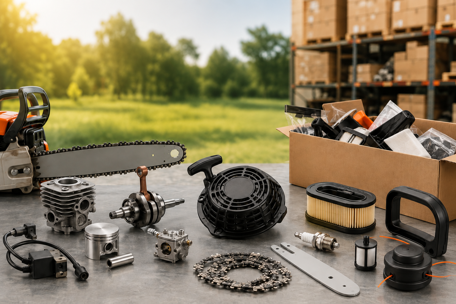
Sourcing outdoor power equipment parts and accessories becomes complicated long before the order becomes large. A distributor may handle only a few machine families, yet the service parts behind them can run into dozens or hundreds of SKUs. Some items arrive with clear part numbers. Others come as workshop photos, old samples, or descriptions such as “starter for this model.”
The challenge is not simply finding a factory that sells carburetors, recoil starters, ignition coils, cylinders, pistons, crankshafts, or gearboxes. The harder part is keeping every component tied to the correct machine, controlling mixed-SKU orders, and making sure the same part can be identified again when stock needs replenishing.
For dealers and distributors, a good parts supplier should make that process easier—not add another layer of uncertainty.
A Spare-Parts Order Is Not Just a Longer Machine Order
Complete machines are relatively straightforward to specify. A buyer confirms the model, quantity, configuration, packaging, and destination.
Parts orders behave differently.
One inquiry may contain 40 or 50 separate lines. Another may combine components from several machine families, with different quantities for every item. Some parts move quickly in the local market, while others are only needed occasionally for workshop repairs.
This creates a different purchasing workload. A distributor has to manage compatibility, SKU identification, packaging references, quantities, and future reorder information at the same time.
A cheap quotation is of limited value if several components turn out to be wrong once the shipment reaches the workshop.
Start with the Machine, Not Just the Part Name
“Carburetor,” “ignition coil,” or “recoil starter” is rarely enough information for reliable matching.
A useful inquiry should start with the machine itself. Whenever possible, provide:
- Machine or engine model
- Existing part number, if available
- Clear photos of the original component
- Required quantity
- Key dimensions when the match is uncertain
- Visible markings, connectors, splines, threads, or mounting points
Photos become particularly useful when the original packaging or documentation is no longer available. For older machines, a clear image of the part and its mounting area can often provide more useful information than a general description.
A real sourcing example
A Tanzanian agricultural equipment retailer once approached NEWTOP with a requirement for dozens of different PJH sprayer parts. The quantity of each item was relatively small—fewer than 1,000 pieces per SKU—and several components were not items commonly produced in large volumes.
The request was handled by matching the customer’s machine references and product images rather than treating each line as an unrelated part. Within two days, the required items had been identified and organized for quotation.
The difficult part was not one unusual component. It was keeping a long list of small requirements correctly matched to the machines they belonged to.
This kind of inquiry is much closer to a real distributor parts order than a purchase of 5,000 identical pieces.
Compatibility Comes Before Price
Two components can look almost identical and still differ where it matters.
A recoil starter may use a different mounting-hole pattern. An ignition coil may have a different connector or fixing position. Crankshafts can vary in shaft dimensions or thread details. Cylinders, pistons and gearboxes may have version differences that are difficult to identify from a catalog image alone.
Depending on the part, confirmation may involve checking mounting positions, dimensions, shaft diameters, threads, splines, connectors, sealing surfaces or other model-specific details.
This also applies to parts described as direct replacements. Fitment should be confirmed against the relevant machine model and available reference information before a bulk order is finalized.
At NEWTOP, parts can be matched according to the customer’s machine model, photos, and confirmed requirements. Buyers can then choose between a complete matching parts set and individual components, subject to the applicable MOQ.
Complete Parts Set or Individual Parts?
The better option depends on how the dealer sells and services equipment.
| Buying Format | Better Suited To | Main Benefit |
|---|---|---|
| Complete Parts Set | Dealers building service coverage around one machine platform | Broader parts coverage in one purchase |
| Individual Parts | Dealers with existing repair or sales data | Replenish only the SKUs currently needed |
A complete set can be useful when a distributor is entering a new machine category or wants a broader repair range available from the start.
Individual components make more sense once the local market has shown which parts turn over fastest. A dealer may then replenish carburetors, recoil starters, ignition coils, cylinders, pistons, crankshafts, gearboxes, or other frequently requested items separately.
In practice, many distributors use both. Core machine families receive broader parts coverage, while proven fast-moving SKUs are reordered individually.
Managing Outdoor Power Equipment Parts and Accessories Across Multiple SKUs
A typical aftermarket order does not always look impressive on paper.
It may include 30 pieces of one component, 60 of another, several dozen of a third item, and another 20 or 30 SKUs in smaller quantities. Once multiple machine categories are involved, the number of lines grows quickly.
This is where one-stop sourcing becomes more useful than simply having a long product catalog.
NEWTOP can support mixed-SKU purchasing across dozens or even hundreds of spare-part items, provided the MOQ for the relevant products is met. Small-batch, multi-SKU requirements can be handled within the same sourcing project.
Depending on the inquiry, the order can include:
- Parts identified from machine models
- Components matched from customer photos
- Complete matching parts sets
- Individual replacement parts
- Complete machines with corresponding spare parts
- OEM packaging
- Customer-specific part numbers
- Barcode labels
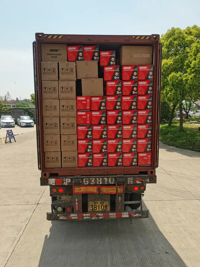
For a distributor already buying machines, adding related service parts to the same purchasing plan can also reduce coordination work. Machines and spare parts do not need to move through completely separate supply chains.
The same applies to packaging and inventory references. If the buyer already uses internal part numbers or barcodes, those identifiers can be incorporated into OEM packaging after the details are confirmed.
This becomes increasingly important as the catalog expands.
Saving a few cents on one component may not mean much if the purchasing team has to coordinate ten different suppliers, reconcile several numbering systems, or re-identify parts every time the workshop needs stock.
For businesses buying outdoor power equipment parts and accessories regularly, efficiency has to be measured across the full order, not only at SKU level.
How Parts Quality Is Checked Before Shipment
Parts inspection should not stop at appearance.
Different components have different failure risks. Dimensional accuracy may be critical for one item, while hardness, rotational balance, sealing performance, or material composition may matter more for another.
NEWTOP uses professional inspection equipment for incoming components, with the inspection method selected according to the part and the relevant quality requirement.
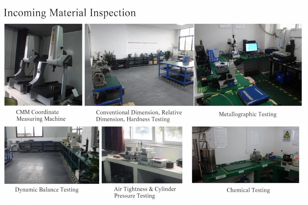
The available inspection methods include:
| Inspection Area | Typical Check |
|---|---|
| Dimensions | Conventional dimensions, relative dimensions, and CMM measurement |
| Material | Hardness, metallographic, and chemical testing |
| Rotating Components | Dynamic balance testing |
| Cylinder-Related Parts | Air-tightness and cylinder-pressure testing |
A coordinate measuring machine, or CMM, can be used where more precise dimensional or positional relationships need to be checked.
Dynamic balance testing is relevant to rotating components where imbalance may contribute to vibration or unstable operation.
For cylinder-related components, air-tightness and cylinder-pressure testing can be applied where sealing performance needs to be verified. Metallographic and chemical testing are available when material structure or composition requires further examination.
Not every component goes through every test. The inspection should match the part and its quality risk.
That distinction is useful when comparing suppliers. Asking how a specific part is checked usually tells a buyer more than asking whether “quality inspection” is available.
Make the First Order Easier to Reorder
The first quotation gets most of the attention, but the real test of a parts supply system often comes months later.
A workshop asks for the same starter again. The warehouse has a product code that the supplier does not recognize. The previous quotation only says “starter assembly.” Someone then has to find an old photo and begin the matching process again.
This is avoidable.
Keep the Reference, Not Just the Part Name
Once a part has been confirmed, it helps to keep a simple record of:
- Supplier part number
- Customer part number
- Machine model
- Confirmed fitment
- Product photo
- Barcode
- Packaging reference
- Previous order quantity
If the distributor already uses an ERP, catalog, or warehouse coding system, its own references can also appear on OEM labels and packaging.
The benefit is simple: purchasing, warehouse, sales, and service teams can refer to the same item in the same way.
It becomes even more useful when machines and spare parts are sourced through the same platform. Equipment already sold in the market can be linked to the service parts needed later, and future machine shipments can include the replacement items that workshops are actually consuming.
A well-organized second order should sound less like:
“Can you identify this part?”
and more like:
“Please replenish these confirmed SKUs.”
That is a much healthier aftermarket supply process.
What to Send When Requesting a Parts Quote
A good spare-parts RFQ does not need to be complicated. It simply needs enough information for the supplier to identify each item correctly.
A Practical RFQ Checklist
Prepare:
- Machine or engine model
- Part name and part number, if available
- Clear photos of the original part
- Quantity required for each SKU
- Dimensions or physical sample if fitment is uncertain
- Complete-set or individual-part requirement
- OEM packaging, barcode, or customer part-number requirements
- Destination country and shipping requirements
For an inquiry containing many SKUs, a spreadsheet with one item per row is usually much easier to manage than dozens of separate messages and photos.
If a component cannot be identified confidently, it is better to leave it pending for confirmation than to force a match simply to complete the quotation.
Good parts sourcing should also become simpler with every reorder. Once the machine model, fitment, part number, packaging, and buyer reference have been recorded, the same component should not need to be identified from the beginning every time inventory runs low.
For dealers and distributors, a reliable outdoor power equipment parts and accessories supplier is therefore not simply a company with a large catalog. The stronger partner is one that can handle mixed SKUs, confirm compatibility, support appropriate quality inspection, and keep future replenishment organized.
NEWTOP combines complete machines and replacement parts within one sourcing platform. Buyers can source complete matching parts sets, individual components, or machines and service parts together according to their market requirements and MOQ.
The first parts order may still require careful matching. The important part is making sure the second, third, and fourth orders become easier.
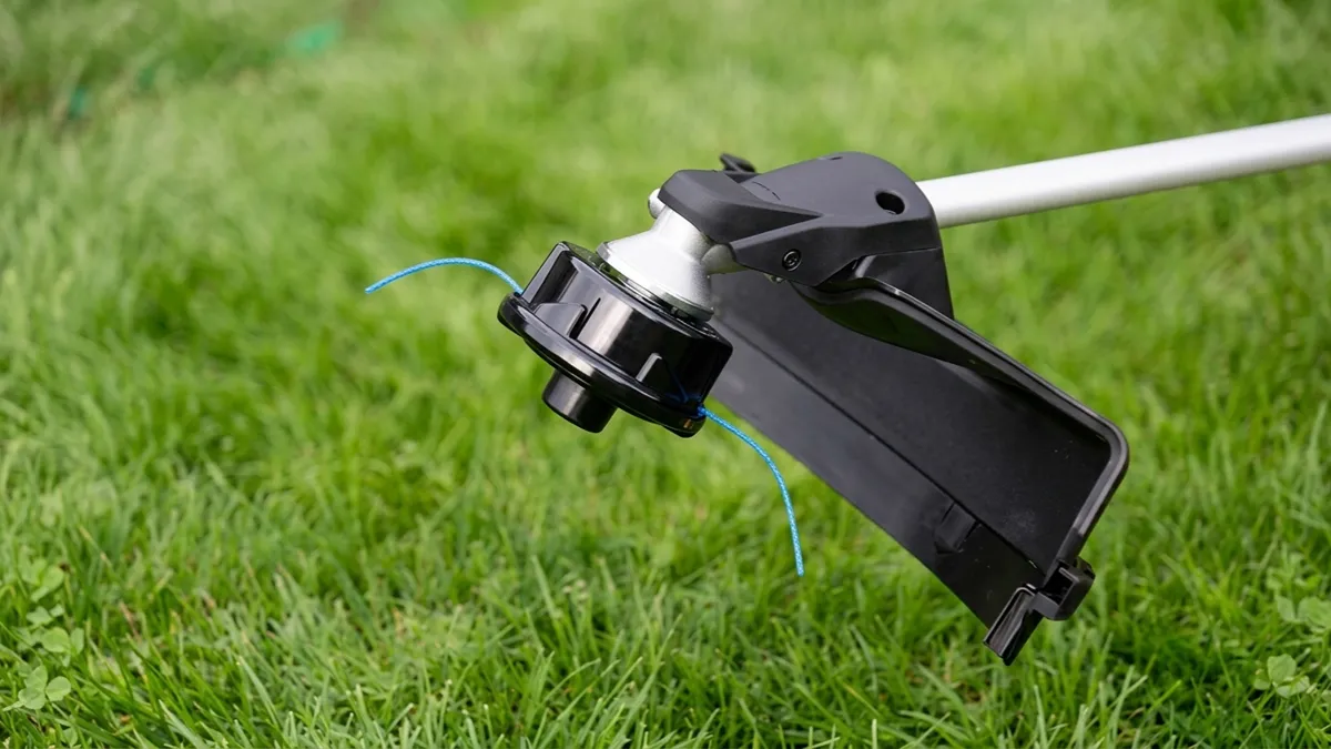
Choosing the right string trimmer head can affect cutting performance, line consumption, machine load, and operator efficiency. A head designed for light lawn trimming may not be suitable for dense weeds or brush, while a heavy-duty blade system can be unnecessary for simple grass edging.
Broadly speaking, string trimmer heads can be classified in several ways, including feeding mechanism, line loading method, cutting medium, line outlet configuration, and blade design. Understanding these differences helps users select a cutting system that matches the machine and the job.
This guide explains the main types of trimmer heads, how they work, what applications they suit, and how to check compatibility before replacing one.
What Is a String Trimmer Head?
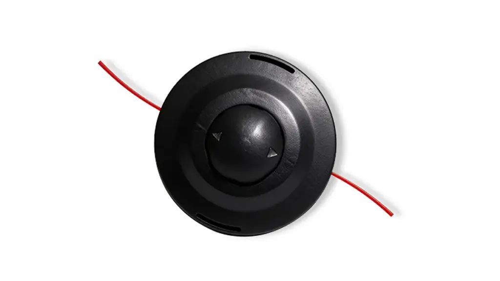
A string trimmer head is the cutting assembly installed at the bottom of a string trimmer or brush cutter shaft. It holds the cutting line and controls how the line is released as the head rotates. When the engine or motor drives the shaft, the trimmer head spins at high speed, causing the nylon line to extend outward and cut grass, weeds, and other light vegetation.
Main Components of a String Trimmer Head
A typical string trimmer head consists of several key components. The exact structure depends on the head type, but the main parts usually include:
- Housing: The outer body protects the internal components and holds the cutting system together.
- Spool: Used in spool-type heads to store the wound nylon line.
- Trimmer Line: The nylon cutting material that contacts and cuts grass and weeds.
- Feed Mechanism: Controls how additional line is released. Bump feed heads use a bump mechanism, while automatic-feed designs use an internal release system.
- Bump Knob: Found on many bump feed heads. It allows the operator to release more line by tapping the head against the ground.
- Cover or Cap: Holds the spool and internal parts in place and allows access for line replacement.
- Mounting Nut or Adapter: Connects the trimmer head to the machine’s drive shaft. The thread and mounting system must match the trimmer.
- Eyelets or Line Openings: Guide the nylon line from the inside of the head to the outside during operation.
How Are String Trimmer Heads Classified?
String trimmer heads can be classified from several different angles because one head can belong to more than one category at the same time.
The most common classification methods are:
- By feeding mechanism: bump feed, automatic feed, and fixed line.
- By line loading method: manual wind, easy-load/speed-feed, and pre-wound spool.
- By cutting medium: nylon line, metal blade, wire, or wire brush.
- By line outlet configuration: single-line, dual-line, and multi-line.
- By blade design: 2-tooth, 3-tooth, 4-tooth, circular saw, and cut-out blade designs.
Different Types of String Trimmer Head Comparison
| Trimmer Head Type | Feed Mechanism | Line Spooling / Loading | Compatible Line Diameter | Key Advantages | Key Disadvantages | Best Use Cases |
|---|---|---|---|---|---|---|
| Bump Feed Head Industry Standard |
Bumps on ground; spring & ratchet release line via centrifugal force | Moderate (Requires housing disassembly & manual winding) |
0.065″ – 0.105″ (1.6mm – 2.7mm) |
• Precise line consumption control • Feeds line on-the-fly without stopping engine • High overall operational efficiency |
• Bottom cap wears down from ground bumps • Excessive force can over-feed line |
Regular lawn maintenance, commercial landscaping, edge trimming |
| Easy Load / Speed Feed Top Recommendation |
Bump feed mechanism (Advanced version) | Very Easy (No disassembly; feed line through and twist spool) |
0.080″ – 0.105″ (2.0mm – 2.7mm) |
• Eliminates line tangling & tedious disassembly • Fast reloading (under 30 seconds) • Combines bump-feed speed with easy line loading |
• Internal ratchets can jam if hard debris gets inside • Slightly higher unit cost |
Pro landscapers, homeowners seeking fast line replacement |
| Automatic Feed (Auto Feed) Beginner Friendly |
Auto-releases fixed length on throttle / switch trigger release | Easy (Often uses pre-wound replacement spools) |
0.065″ – 0.080″ (1.6mm – 2.0mm) |
• 100% hands-free line feeding • No ground bumping required • Extremely easy for beginners |
• Higher line consumption • Cannot manually control line output • Troubleshooting line jams can be tedious |
Small residential lawns, light trimming, DIY homeowners |
| Fixed Line Head Heavy Duty |
None (Uses pre-cut individual line strips) | Very Easy (Push-in / lock pre-cut lines directly) |
0.105″ – 0.155″ (2.7mm – 4.0mm) |
• Zero line welding or internal tangling risks • Supports ultra-thick & serrated heavy-duty lines • Maximum durability in tough debris |
• Must stop machine to manually replace worn line • Cannot feed continuously |
Thick weeds, overgrown areas, brush edge clearing |
| Blade Trimmer Head Hard Cutting |
Lineless (Utilizes plastic or metal blades) | N/A (Replace individual worn blades via screws/clips) |
N/A (Replaces nylon lines entirely) |
• Extremely high cutting force • Cuts heavy weeds & small woody shoots easily • No line wearing or snapping |
• Higher risk of projectile debris / injury • Blades chip/shatter against stone or concrete |
Heavy brush clearing, thick weeds, dense vegetation |
| Steel Wire Brush Head Special Purpose |
Lineless (High-tensile twisted steel wire bristles) | N/A (Replace entire wire wheel assembly) |
N/A (Heavy steel wire bundle) |
• Highly abrasion-resistant on hard surfaces • Scrapes off moss, weeds, and rust effectively |
• Heavy weight puts extra load on motor/gearbox • High thrown-object risk (requires protective gear) |
Pavement cracks, sidewalk moss, driveway joint weeding |
Note: The recommended line diameter ranges shown below are industry reference values only. Actual line compatibility may vary depending on the trimmer head design, machine power, and manufacturer specifications. Always check the user manual or product specifications before selecting a trimmer line.
Types of String Trimmer Heads by Feeding Mechanism
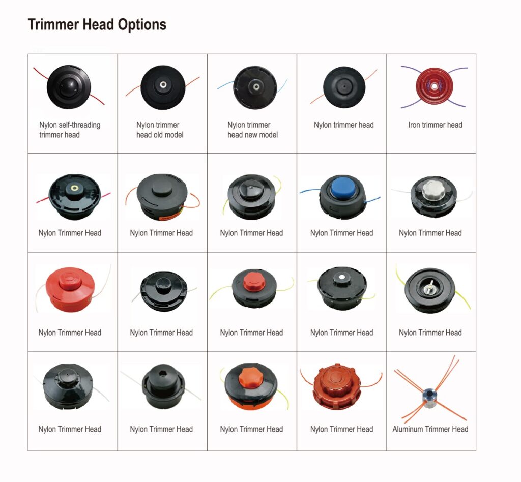
The feeding mechanism determines how the cutting line is released during operation. It directly affects user convenience, line consumption, and maintenance requirements. Different feeding systems are designed for different working conditions, from occasional lawn trimming to frequent professional landscaping tasks. The most common feeding methods include bump feed, automatic feed, and fixed line systems, each offering a different balance between control, efficiency, and simplicity.
Bump Feed Trimmer Heads
A bump feed trimmer head uses a spool system that releases additional nylon line when the operator taps the rotating head against the ground. The impact activates a mechanical feeding mechanism, allowing centrifugal force to pull more line through the outlet holes. This design provides good control because users can decide when to extend the line. Its advantages include simple operation, wide compatibility, and easy maintenance. However, the bump knob and internal components may wear after frequent ground contact, especially in commercial applications. Bump feed heads are widely used for general grass cutting, lawn edging, and weed trimming.
Explore NEWTOP’s trimmer head solutions for brush cutters to find the right replacement option for your application.
Automatic Feed Trimmer Heads
An automatic feed trimmer head uses an internal mechanism to release cutting line automatically during operation without requiring the operator to bump the head. Depending on the design, the system may use centrifugal force, a spring mechanism, or a preset feeding structure to maintain the correct line length. The main advantage is improved convenience, especially when covering large areas where frequent manual adjustment is inefficient. However, automatic feed systems may consume more line if they release excessive length, and their internal mechanisms usually require more precise manufacturing compared with bump feed designs.
Fixed Line Trimmer Heads
A fixed line trimmer head works differently from spool-based systems because it uses individual pre-cut pieces of nylon line inserted directly into the head. During operation, the fixed line rotates with the head and cuts vegetation through high-speed impact. This structure eliminates spool winding problems and allows quick line replacement, making it suitable for users who prefer simple maintenance. Fixed line heads are often used with thicker line for tougher grass and weeds. The main limitation is that the operator must manually replace worn line sections instead of extending line automatically during cutting.
Scale Your Business With Durable Power Equipment

Types of String Trimmer Heads by Line Loading Method
The line loading method describes how new cutting line is installed into the trimmer head. While all line-based heads perform the same basic cutting function, their loading designs can greatly affect replacement speed and user experience. Traditional manual winding systems focus on simple structure and reliability, while modern easy-load and pre-wound spool designs are developed to reduce downtime and make maintenance easier.
Manual Wind Trimmer Heads
A manual wind trimmer head requires the operator to manually wrap nylon line around an internal spool before installation. The line must be wound evenly and in the correct direction to ensure smooth feeding during operation. This design is one of the most traditional and widely used systems because of its simple structure, low manufacturing cost, and reliable performance. However, replacing line takes more time compared with modern easy-load systems, and incorrect winding can cause line jams or uneven feeding. Manual wind heads are commonly used in residential and professional-grade trimmers where durability and cost efficiency are important.
Easy Load / Speed Feed Trimmer Heads
An easy load or speed feed trimmer head is designed to simplify the line replacement process by reducing the need to disassemble the spool or manually wind the entire line. In many designs, the operator inserts the line directly through the head and rotates the spool to load it evenly. This system improves maintenance efficiency and reduces downtime, making it popular among professional landscapers and commercial users. The main advantage is faster line installation, while the disadvantage is that the structure is usually more complex and may require higher manufacturing precision compared with traditional manual wind heads.
Pre-Wound Spool Trimmer Heads
A pre-wound spool trimmer head uses a replacement spool that has nylon line already installed by the manufacturer. When the line is exhausted, users simply remove the old spool and install a new one instead of winding fresh line manually. This provides the fastest and easiest replacement process, especially for occasional users who prioritize convenience. However, pre-wound spools usually have higher replacement costs and require users to purchase compatible spool sizes. This type is commonly found on consumer-grade electric and battery-powered trimmers where ease of use is a major purchasing factor.
Types of String Trimmer Heads by Cutting Medium
The cutting medium is the actual material that contacts and removes vegetation. Different materials provide different levels of cutting strength, flexibility, durability, and safety. Nylon line is commonly used for general grass trimming, while metal blades and wire-based systems are designed for tougher vegetation or specialized applications.
Nylon Line Trimmer Heads
Nylon line trimmer heads are the most common cutting systems used for grass trimmers and brush cutters. They rely on flexible nylon line rotating at high speed to cut grass and weeds through impact force. Different line diameters, shapes, and materials can affect durability, cutting efficiency, and resistance to breakage. Nylon heads offer excellent safety because the flexible line is less likely to cause damage when contacting hard surfaces. However, they are less effective against thick brush, woody stems, or dense vegetation. They are ideal for lawn maintenance, trimming edges, and general landscaping applications.
Blade Trimmer Heads
A blade trimmer head uses rigid metal blades instead of flexible nylon line to provide stronger cutting performance. The rotating blade cuts vegetation through direct contact, making it suitable for thick grass, heavy weeds, and small brush that may quickly wear down nylon line. Blade systems offer higher cutting power and longer service life in demanding applications, but they require stronger machines, proper safety guards, and correct installation. Because metal blades generate higher impact forces, they are mainly used with professional brush cutters rather than lightweight residential string trimmers.
Wire and Wire Brush Trimmer Heads
Wire and wire brush trimmer heads use metal wire elements or brush-style cutting materials to remove tough vegetation, moss, weeds, and surface growth. Instead of cutting with a sharp edge, the rotating wire creates an abrasive cleaning and cutting action. These heads can be useful for specialized tasks such as removing weeds between paving stones or cleaning hard surfaces.
Types of String Trimmer Heads by Line Outlet Configuration

The line outlet configuration refers to the number and arrangement of cutting line ends extending from the trimmer head. This design affects cutting coverage, efficiency, and the load placed on the trimmer motor or engine. Single-line systems are usually designed for lighter applications, while dual-line and multi-line heads provide increased cutting performance for larger areas and heavier grass conditions.
Single-Line Trimmer Heads
A single-line trimmer head uses one piece of nylon line extending from the head during operation. Because it has fewer moving components and lower rotating resistance, it is often used on lightweight trimmers designed for residential lawn care. Single-line systems provide stable operation, lower line consumption, and easier maintenance compared with multi-line designs. However, they generally provide less cutting coverage and lower cutting efficiency when dealing with dense vegetation. They are suitable for light trimming, lawn edges, and areas where precision is more important than maximum cutting speed.
Dual-Line and Multi-Line Trimmer Heads
A dual-line or multi-line trimmer head uses two or more cutting line ends extending from the head, increasing the number of cutting points during rotation. This design improves cutting efficiency and allows the machine to remove more vegetation with each rotation. Multi-line heads are commonly used for heavier grass and professional landscaping applications. However, additional line increases air resistance and places more load on the engine or motor. Therefore, these heads require sufficient machine power and proper line diameter selection to maintain performance and avoid excessive wear.
Types of Metal Blade Trimmer Heads by Blade Design
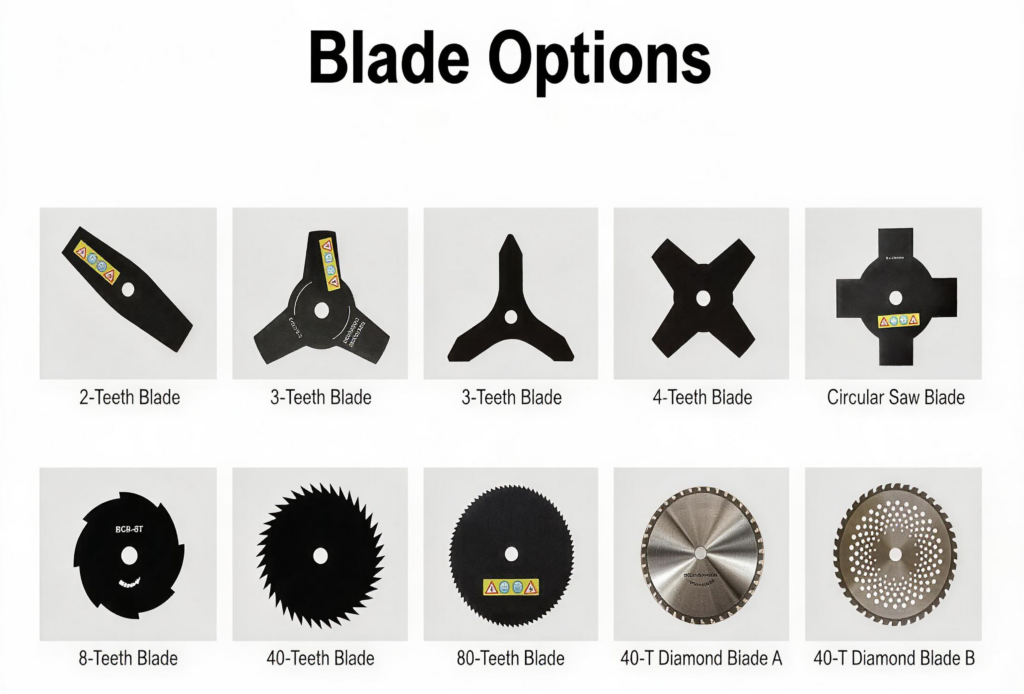
Metal blade heads are mainly used on brush cutters and heavy-duty trimming equipment where nylon line cannot provide enough cutting force. The blade shape, tooth number, and overall structure determine how efficiently the blade cuts different types of vegetation.
2-Tooth Straight Blades
A 2-tooth straight blade features two cutting edges positioned opposite each other on the blade disc. Its simple design provides good balance, low rotating weight, and efficient cutting performance for lighter vegetation. Because it has fewer teeth, it can maintain high rotational speed with less power demand compared with multi-tooth blades. These blades are commonly used for grass cutting and soft weeds. However, they are not designed for dense brush or woody plants because the limited number of cutting edges reduces their ability to handle tougher materials.
3-Tooth Blades
A 3-tooth blade is one of the most commonly used brush cutter blades because it provides a balance between cutting strength, control, and versatility. The three cutting edges distribute impact force more evenly while maintaining efficient rotation. This design is suitable for medium-density grass, weeds, and general vegetation management. Compared with 2-tooth blades, 3-tooth designs offer improved cutting coverage, while remaining lightweight enough for many brush cutters.
4-Tooth Blades
A 4-tooth blade provides additional cutting edges compared with 2-tooth and 3-tooth designs, improving cutting consistency when working through thicker vegetation. The increased number of teeth allows more frequent contact with plants during rotation, which can improve cutting efficiency. However, the additional material also increases blade weight and requires appropriate machine power. Four-tooth blades are often used for heavier grass and tougher weeds where users need stronger performance than standard nylon line systems but do not require a circular saw blade.
Circular Saw Blades
A circular saw blade uses multiple sharp teeth around the outer edge, similar to a traditional saw. Unlike grass-cutting blades, it is designed to handle much tougher vegetation, including thick brush, small woody stems, and young saplings. The large number of teeth provides aggressive cutting performance, but it also requires higher engine power, correct blade mounting, and professional operating practices. Circular saw blades are typically used with heavy-duty brush cutters and should only be installed on machines specifically designed to support this type of cutting attachment.
Cut-Out and Hollowed Blade Designs
Cut-out and hollowed blade designs use openings or reduced material areas in the blade body to decrease weight while maintaining cutting strength. These designs help reduce rotating mass, improve machine balance, and lower operator fatigue during extended use. The cut-out structure can also improve handling by reducing resistance during rotation. Different opening patterns are developed for specific vegetation conditions, from grass management to heavier brush cutting. As with all metal blades, performance depends on matching the blade design with the brush cutter power, guard system, and intended working environment.
How to Choose the Right Trimmer Head for Your Yard
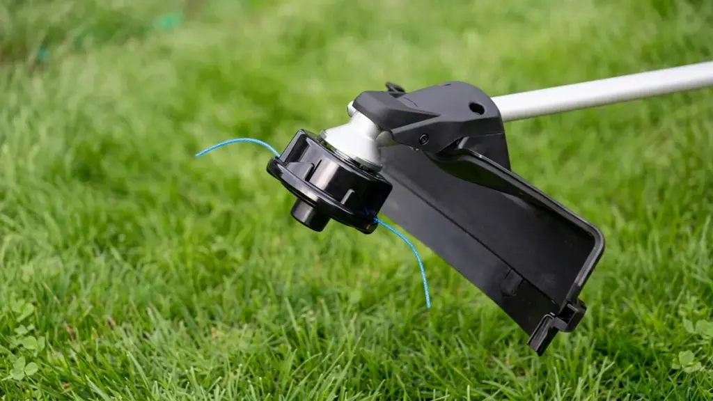
Start with the vegetation, then consider the machine.
For normal lawn grass and edging, a nylon-line head is usually the most practical choice. A bump-feed or automatic-feed design can make frequent line adjustment easier.
For thick weeds and tall grass, choose a stronger head and a suitable line diameter. If the vegetation becomes woody or brush-like, a compatible metal blade may provide better cutting performance.
You should also consider:
- Machine power: Heavy heads and blades require suitable engine power.
- Cutting material: Nylon line is suitable for general trimming; blades are better for tougher vegetation.
- Line diameter: Thicker line provides greater durability but increases machine load.
- Working frequency: Commercial users may benefit from easy-load or speed-feed systems.
- Maintenance: A simple head can be preferable when fast servicing is important.
How to Match a Trimmer Head With Line Diameter
Line diameter should match both the trimmer head and machine power.
Thin line is generally suitable for light grass and requires less power to accelerate. Thicker line provides better resistance to wear and breakage and is more suitable for dense grass and weeds.
However, using the thickest possible line is not always better. Oversized line can increase engine load, reduce rotational speed, and interfere with the feeding mechanism.
Always check the string trimmer head manufacturer’s recommended line diameter before changing from the original specification.
How to Know if a Trimmer Head Fits Your String Trimmer
A replacement head must match the machine’s mechanical and operating specifications. Check:
- Mounting thread and shaft connection
- Adapter requirements
- Rotation direction
- Maximum line diameter
- Maximum cutting diameter
- Engine or motor power
- Head weight
- Machine model compatibility
The term “universal trimmer head” does not mean that one head fits every string trimmer. Universal products usually support several common mounting systems through adapters.
For wholesale buyers and equipment distributors, checking the exact compatibility list is safer than selecting a head based only on appearance or thread size.
NEWTOP String Trimmer Heads for Different Applications
NEWTOP supplies string trimmer heads and brush cutter cutting accessories for different grass, weed, and vegetation applications. The product range includes different head structures and mounting configurations to support various brush cutter models.
For distributors and importers, selecting a cutting head is not only about the individual accessory. The head, nylon line, blade, brush cutter, and application should work as one complete cutting system.
NEWTOP can support customers looking for outdoor power equipment and replacement cutting components for different market requirements, including product selection and wholesale sourcing.
Looking for string trimmer heads or brush cutter cutting systems for your market? Contact NEWTOP to discuss suitable models, specifications, and sourcing options.
Frequently Asked Questions
What are the different types of string trimmer heads?
String trimmer heads can be classified by feeding mechanism, loading method, cutting medium, line outlet configuration, and blade design. Common types include bump-feed, automatic-feed, fixed-line, manual-wind, easy-load, pre-wound spool, nylon-line, and metal-blade heads.
What is a bump feed trimmer head?
A bump feed head stores line on an internal spool. When the line wears down, the operator taps the spinning head against the ground. This compresses a spring mechanism to release a short, controlled amount of line without having to stop the machine.
Are universal trimmer heads really universal?
Not necessarily. Universal heads normally fit several common mounting systems rather than every trimmer on the market. Always check the thread, adapter, rotation direction, line capacity, and machine compatibility before installation.
What is the easiest trimmer head to load?
Speed-feed or easy-load bump heads are widely considered the easiest to reload. They feature an external loading path where you push the line straight through the eyelets and twist a knob or plate to wind it. This eliminates the need to open the housing or manually wrap a spool, often taking under 30 seconds.
Can I put a fixed line head on my string trimmer?
Yes, provided the fixed line head matches your trimmer’s arbor size, thread direction, and power rating. Because fixed line heads often use thicker line intended for heavy brush and weeds, they perform best on larger gas trimmers rather than low-power consumer units.
What is the difference between automatic and bump feed trimmer heads?
The main difference comes down to user control. A bump feed head requires you to manually tap the ground to advance line, which helps minimize wasted line. An automatic head senses when the line is short or the motor load changes and advances the line on its own, providing continuous cutting but typically consuming line faster.
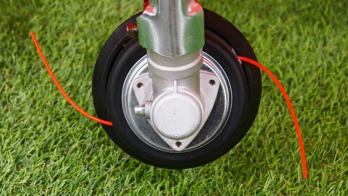
Choosing the right string trimmer line size can make yard work faster, cleaner, and much easier. Use a line that is too thin, and it may snap repeatedly when cutting thick grass or weeds. Choose one that is too thick, and your trimmer may lose cutting speed, use more power, or put extra load on the trimmer head.
So, what diameter should you use? Is 0.080″ enough for normal grass, or is 0.095″ better for weeds? When does it make sense to move up to 0.105″ or 0.130″?
This guide breaks down common string trimmer line diameters, explains which sizes work best for different yard conditions, and compares popular line shapes. Whether you are maintaining a small lawn or tackling dense weeds and heavy vegetation, you will learn how to match the line to both the job and your trimmer.
What Is String Trimmer Line?
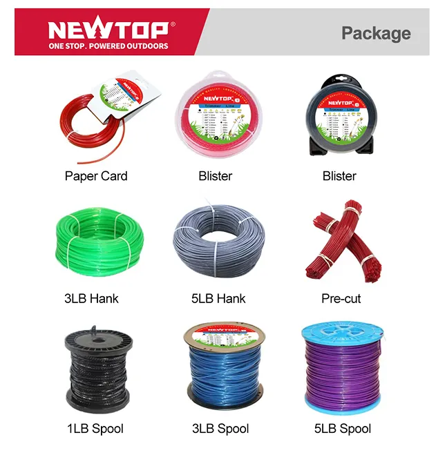
String trimmer line, also called trimmer cord or weed eater line, is the flexible cutting material used by string trimmers and brush cutters. It rotates at high speed around the trimmer head and cuts grass and weeds through impact and friction.
Related Reading: Types of String Trimmer Heads
Most trimmer lines are made from durable nylon or nylon-based materials. Some professional-grade lines use reinforced or co-extruded materials to improve wear resistance and reduce breakage.
The line diameter is one of the most important specifications. Common sizes range from about 0.065 (1.65 mm) inches to 0.155 inches (3.94 mm), although some heavy-duty machines can use larger diameters.
A larger diameter generally provides:
- Better durability
- Higher resistance to breaking
- Better performance in thick vegetation
- More cutting power for demanding jobs
However, thicker does not always mean better. The trimmer head and engine must be designed to handle the selected line.
What String Trimmer Line Sizes Are Available?
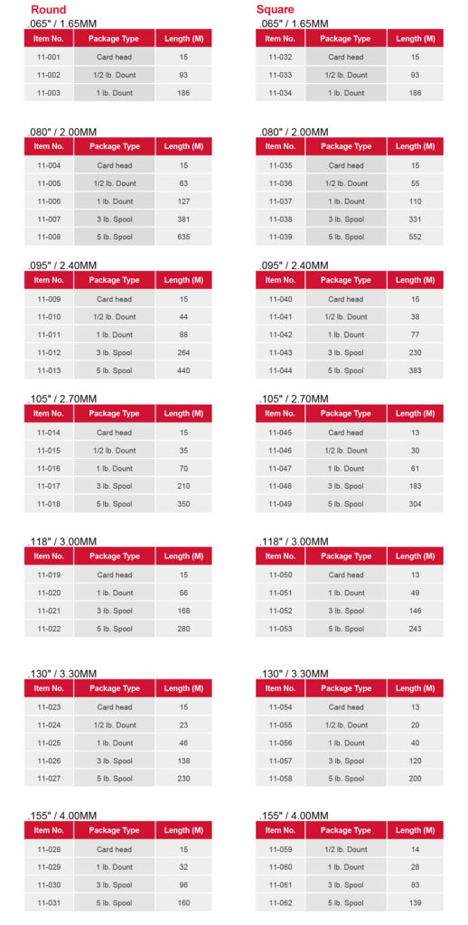
String trimmer line is commonly sold by diameter in inches. The most widely used sizes include 0.065″, 0.080″, 0.095″, 0.105″, and 0.130″.
Smaller diameters are suitable for light grass and residential trimming. Medium diameters provide a balance between cutting performance and durability. Larger diameters are designed for thick weeds, dense vegetation, and heavier-duty work.
The table below gives a quick overview:
| Line Diameter | Typical Application | Cutting Conditions |
|---|---|---|
| 0.065″–0.080″ (1.65–2.03 mm) |
Light trimming | Soft grass and lawn edges |
| 0.080″–0.095″ (2.03–2.41 mm) |
General yard work | Regular grass and moderate weeds |
| 0.095″–0.105″ (2.41–2.67 mm) |
Heavy residential or professional use | Thick grass and tough weeds |
| 0.105″–0.130″ (2.67–3.30 mm) |
Heavy-duty cutting | Dense weeds and rough vegetation |
| 0.130″+ (3.30 mm+) |
Professional heavy-duty work | Heavy brush and demanding conditions |
High-Margin Garden Equipment for Global Distributors
How to Choose String Trimmer Line Size for Different Grass Types
For soft lawn grass, a smaller line can provide fast cutting with less engine load. For thick, dry, or tough grass, a medium or large diameter is usually more suitable because it can withstand repeated impacts.
Consider three factors:
Grass density: Dense grass creates more resistance against the line.
Stem toughness: Tough weeds and dry vegetation require a stronger cutting line.
Machine power: A larger line needs more rotational energy. A small trimmer may struggle with oversized cord.
Short, Soft Turf and Light Edging
Fine turf species like Kentucky bluegrass, fescue, and ryegrass require a gentle touch to avoid scalping. A thinner diameter protects delicate flower beds, sprinkler heads, and patio edges during routine maintenance.
Using a lightweight cord prevents small electric trimmers from bogging down while spinning. For these manicured areas, rely on the following specifications:
- Recommended diameter: 0.065″ to 0.080″ round line
- Target vegetation: Soft turf kept at standard mowing heights
- Key benefit: Minimizes tearing of thin grass blades
Standard Residential Lawns and Mixed Weeds
Most typical suburban yards feature a mix of regular turf and common weeds like dandelions, clover, and young crabgrass. You need a versatile cord that handles weekly perimeter maintenance along fences, driveways, and trees without breaking every five minutes.
This category hits the sweet spot for mid-range gas and 40-56V battery trimmers, offering a perfect balance between cutting strength and flexibility.
- Recommended diameter: 0.080″ to 0.095″
- Primary application: Default all-purpose residential use
- Optimal equipment: Mid-range gas and 40-56V battery units
Thick Turf, Mature Grass, and Tough Weeds
Neglected yard corners and overgrown sections quickly outmatch standard homeowner line. When facing thick-stemmed weeds like mature plantain or coarse sedges, you need a cord with enough physical mass to maintain its momentum.
A heavier cord slices straight through dense clumps instead of folding over on impact. It also resists rapid fraying and snapping when making repeated contact with retaining walls or concrete foundations.
- Recommended diameter: 0.085″ to 0.110″
- Target vegetation: Mature grass and tough, fibrous stems
- Durability advantage: Survives heavy impact with hard landscape obstacles
Tall Grass, Dense Brush, and Heavy Vegetation
Clearing coarse pasture grass, drainage ditches, nettles, and brambles demands serious cutting power. This rough terrain pushes string trimmers to their absolute limits, often requiring heavy-duty lines to tear through small woody saplings.
Operators working in these extreme conditions frequently switch from round lines to square, serrated, or twisted profiles. These aggressive shapes bite directly into fibrous stems for faster clearing.
- Recommended diameter: 0.110″ and above (often 3.0 mm to 3.3 mm+)
- Equipment requirement: Commercial-grade trimmers or walk-behind brush cutters
- Preferred profiles: Square, serrated, or twisted shapes
Aligning Line Size with Trimmer Power
Matching your cord thickness to the vegetation is only half the battle; the machine must actually possess the torque to spin it. Installing a line thicker than the manufacturer’s maximum rating reduces RPMs, resulting in battered, torn grass instead of clean cuts.
Engine displacement and battery voltage strictly dictate what your machine can handle safely.
- Under 40V Electric/Battery: Requires 0.065″ to 0.080″ line to prevent motor strain and overheating.
- Mid-Power Units (20-30 cc gas or 40-56V battery): Optimized to efficiently spin 0.080″ to 0.095″ line.
- Commercial Units (30 cc+ gas): Built to operate 0.095″ to 0.130″+ line without losing critical tip speed.
What Size Trimmer Line Is Best for Light Grass and Small Yards?

For light grass and small yards, stick strictly to 0.065 or 0.080-inch trimmer line. This range maximizes RPMs on low-voltage equipment while preventing damage to delicate hardscapes.
The Core Size Range: 0.065 to 0.080 Inch
The industry-standard size for light grass and small residential trimming falls strictly between 0.065 and 0.080 inches (1.65–2.03 mm). Manufacturers build lightweight consumer trimmer heads specifically around these tolerances to ensure smooth feeding.
A 0.065-inch line is the optimal choice for very light-duty tasks. It excels at touching up short grass and executing clean edges around delicate flower beds without tearing the turf.
A 0.080-inch line provides a slightly more robust, versatile option. It tackles yards requiring regular maintenance and holds up better against minor impacts with garden borders.
Why Thinner Line Suits Small Yard Equipment
Thinner line is highly aerodynamic. This minimal drag allows low-power electric and battery trimmers operating under 40V to maintain high RPMs without overloading the motor.
Using oversized line on small-yard tools causes immediate mechanical stress. It triggers faster battery drain, excessive vibration, and premature wear on drive components.
Round line under 0.080 inches also offers high precision around tight obstacles. You can maneuver close to borders, reducing the risk of scarring tree bark or damaging expensive hardscapes.
Choosing Between 0.065 and 0.080 Inch
Select 0.065-inch line for small, regularly mowed yards featuring soft turf. It pairs perfectly with low-voltage, lightweight trimmers handling basic detail work.
Upgrade to 0.080-inch line if the yard occasionally features taller grass or small weeds. This diameter performs much better for frequent edging against concrete walkways, where thinner cords snap on contact.
Small gas trimmers under 25 cc handle 0.080-inch line comfortably. It offers better resistance to fraying and snap-offs than thinner alternatives, keeping your workflow steady.
What Size Trimmer Line Is Best for Thick Grass and Weeds?

For thick grass and heavy weeds, the 0.095-inch line is the versatile standard. Step up to 0.105-inch for overgrown stalks, provided your equipment has the power.
The Optimal Range: 0.095″ vs. 0.105″ Line
The 0.095-inch (2.4 mm) line acts as the most versatile option for thick turf and heavy residential yard work. It strikes a balance between cutting power and flexibility, allowing you to clear dense patches without immediately bogging down standard landscape equipment.
The 0.105-inch (2.7 mm) line offers superior strength for overgrown grass, thick-stemmed weeds, and intense fence line clearing. Users should start with the 0.095-inch line and only upgrade to the 0.105-inch variant if the line snaps frequently against dense stalks or hard borders.
Matching Line Size to Equipment Power
Mid-range gas trimmers in the 20 to 30 cc category and 40V+ battery units generate enough torque to run 0.095-inch lines efficiently. These machines can maintain the high rotational speeds required to cut cleanly through tough vegetation.
Low-voltage battery models struggle with heavy lines, often resulting in sluggish performance or severe motor strain. Operators must verify the maximum supported diameter in the equipment manual before installing a thicker string to prevent drive system failure.
How Diameter Affects Cutting Efficiency and Durability
String trimmers rely on tip velocity and weight to perform work. Larger diameters carry more physical mass, delivering the momentum needed to slice right through coarse, fibrous vegetation instead of just bending it over.
Upgrading to a 0.095-inch or 0.105-inch size drastically reduces breakage when striking hard surfaces like concrete walls or wood retaining posts. Selecting the smallest effective diameter for your specific terrain prevents unnecessary engine drag and optimizes battery runtimes for long shifts.
What Size Trimmer Line Is Best for Heavy-Duty Brush?

Heavy-duty brush requires line diameters between 0.110 and 0.155 inches. To maintain cutting speed and protect the clutch, always match these thicker lines to commercial-grade engine displacements.
Recommended Line Sizes by Brush Density
Thick, woody brush destroys standard residential trimmer line on impact. To clear dense undergrowth efficiently, you need mass and rigidity. Operators categorize heavy-duty string trimmer line into three primary bands based on vegetation density.
- 0.095 to 0.105 inch: Suited for heavy weeds, thick grass, and light brush using high-powered residential trimmers.
- 0.110 to 0.130 inch: Ideal for thick brush, woody shrubs, and dense vegetation in commercial-grade clearing work.
- 0.155 inch and above: Reserved for extreme-duty clearing and heavy commercial applications.
Matching Line Diameter to Engine Displacement
Pushing a thick line through dense brush creates massive drag. Thicker lines resist breakage but demand significantly more engine torque to maintain cutting speed. If your engine lacks the output to spin a heavy line at peak RPM, the trimmer bogs down and batters the vegetation.
- 25 to 35 cc engines: Perform best with 2.7 to 3.0 mm (approx. 0.110 inch) line.
- 40 cc engines: Provide the necessary torque for 3.0 to 3.5 mm (approx. 0.130 inch) line.
- 40 to 50 cc or larger engines: Required to effectively spin 3.5 to 4.5 mm (0.155 inch and thicker) line.
Choosing the Right Line Shape for Heavy Brush
Profile geometry dictates how the line interacts with woody stems. You must weigh raw cutting power against material wear and motor strain.
- Round line: Offers high durability and resists breaking against hard stems, making it a reliable choice for everyday heavy clearing.
- Square, serrated, or twisted line: Delivers a more aggressive cut through thick brush but tends to wear faster.
Aggressive line profiles place higher drag on the trimmer head. You need adequate engine power to prevent the machine from bogging down when those sharp edges bite into thick stalks.
Equipment Limitations and Capacity Bounds
Manufacturers engineer trimmer heads and clutches for specific load limits. Forcing an oversized line into a head not rated for it guarantees mechanical failure.
- Poor cutting performance: Using a line thicker than the trimmer’s rating causes poor cutting performance and accelerates head wear.
- Mechanical overload: Excessive line weight puts unnecessary strain on the engine and clutch system.
- Strict upper limits: Always treat the manufacturer’s specified maximum line diameter as a strict upper limit to protect the equipment.
Round vs Square vs Star-Shaped Trimmer Line
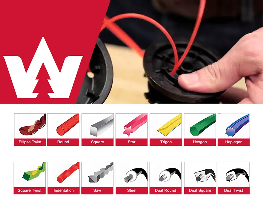
Round line is the most common type. Its smooth surface provides good durability and works well for general grass and weed trimming. It is also less likely to wear unevenly.
Square line has sharper edges that can provide more aggressive cutting on thick grass and weeds. It may be useful for demanding vegetation but can wear differently depending on the working conditions.
Star-shaped or multi-sided line has multiple cutting edges. It is designed to improve cutting efficiency and can perform well on tougher vegetation.
The best shape depends on the job. For everyday lawn maintenance, round line is a reliable choice. For heavier vegetation, square or multi-sided line may provide more aggressive cutting.
Best Applications and Diameter Selection
Match the line shape and diameter directly to the yard conditions and your specific equipment capacity.
- Round Line (0.065-0.095 inch): Use for regular weekly maintenance on typical residential yards using battery or small gas trimmers.
- Square Line (0.080-0.105 inch): Step up to this size for tackling overgrown fence lines, ditch banks, and medium-to-heavy vegetation.
- Star-Shaped Line (0.090+ inch): Reserve these large diameters for heavy-duty cleanup of coarse grasses, thick weeds, and neglected lots.
How to Know Which Trimmer Line Size Your Machine Needs
Match your trimmer line size to your machine’s manual, power output, and the target vegetation. Getting this right maximizes cutting performance and prevents equipment damage.
Check the Owner’s Manual or Trimmer Head
The fastest way to find your required line size is to consult the original documentation. Open your owner’s manual and scan for specifications labeled as cutting line, line diameter, spool capacity, or recommended line size. Manufacturers engineer the trimmer head to operate within these exact tolerances.
If you lost the manual, inspect the equipment directly. You can often find the printed or molded dimensions on the trimmer head, spool cover, or housing. Once you find this number, treat it as a hard limit. Stay strictly within the manufacturer’s specified range rather than choosing by appearance or feel at the hardware store.
Match Line Size to Trimmer Power and Type
Trimmer power directly dictates how thick of a line the motor can spin efficiently. Mismatching the line thickness overloads the drive system and slows down the RPMs.
- Electric and battery-powered trimmers: Generally require smaller diameters, commonly between 0.065 and 0.080 inches (1.6 to 2.0 mm).
- Residential gas trimmers: Support mid-range to thicker lines, often ranging from 0.080 to 0.110 inches.
- Commercial brush cutters: Handle the thickest lines, starting at 0.110 inches and scaling up to 0.155 inches for high-power units.
Matching the line to the motor ensures the tip speed stays high. High tip speed is exactly how the tool slices cleanly through grass instead of just battering it.
Select the Right Diameter for the Vegetation
Once you know what sizes your machine accepts, select the specific diameter based on your yard conditions. Thicker lines deliver more impact force, but they also create more drag.
- 0.065 to 0.080-inch line: Use for light grass, edging, sidewalks, and fences.
- 0.080 to 0.095-inch line: Choose for general lawn maintenance and thicker grass.
- 0.095 to 0.110-inch line (or higher): Opt for heavy weeds, dense growth, and woody stems.
The smartest approach is to apply the smallest line size that reliably completes the task. A thinner line cuts cleaner and minimizes mechanical strain on your machine.
Common Mistakes to Avoid
Many operators try to force a heavier line to do a job the machine wasn’t built to handle. This creates a cascade of mechanical and performance issues.
- Overloading the head: Installing a thicker line than the trimmer is designed for drops cutting performance and damages the head assembly.
- Copying old spools blindly: Buying replacement line based solely on the size of the old spool causes errors, especially if a previous owner modified or replaced the trimmer head.
- Ignoring the limits: Exceeding the maximum allowed diameter just because a thicker line physically fits into the spool housing will overheat the motor.
Stick strictly to the manufacturer specifications. A fast-spinning thin line always outcuts a slow, bogging thick line.
Common String Trimmer Line Problems and Solutions
Even the correct diameter can perform poorly if the line is installed or used incorrectly.
| Problem | Possible Cause | Solution |
|---|---|---|
| Line breaks frequently | Line is too thin or worn | Use the recommended diameter and replace worn line |
| Line does not feed | Incorrect winding | Rewind evenly in the correct direction |
| Poor cutting performance | Line too thin or worn | Use a suitable diameter and fresh line |
| Engine slows down | Line is too thick | Use the manufacturer’s recommended size |
| Line welds together on spool | Excessive heat or poor line material | Use quality line and store it correctly |
| Uneven cutting | Different line lengths | Rewind and adjust both sides evenly |
How to Replace String Trimmer Line
Replacing trimmer line requires matching the exact diameter to your head style, winding it tightly in the designated direction, and testing the feed mechanism before operation.
Safety Checks and Trimmer Preparation
Preparation ensures you do not accidentally trigger the equipment while working near the cutting head. Securing the tool properly speeds up the replacement process.
- Power disconnection: Disconnect the power source by unplugging the cord, removing the battery, or detaching the spark plug.
- Tool positioning: Place the trimmer on a flat surface with the head facing up to provide clear access to the spool.
- Head identification: Identify the specific head style, such as a standard manual-wrap reel, a bump-feed head, or a quick-load system.
Removing the Old Line and Cleaning the Head
Old debris causes friction and stops new line from feeding properly. You need to clear the housing completely before loading fresh cord.
- Head opening: Open the trimmer head by pressing the side release tabs or twisting off the central bump knob.
- Spool removal: Pull the spool out of the housing and completely unravel any leftover string.
- Debris clearance: Wipe away accumulated grass, dirt, and mud from the spool and housing to prevent future jamming.
Selecting and Cutting the New Trimmer Line
Using the wrong line thickness or leaving ragged edges will cause immediate feed issues. Cut the cord cleanly to match your specific equipment ratings.
- Diameter selection: Select the appropriate diameter for the job, typically ranging from 0.065 inches for light grass to 0.095 inches for heavy weeds.
- Length measurement: Measure and cut the manufacturer-recommended length, which usually falls between 10 and 25 feet per spool.
- Clean cuts: Use sharp cutters to create clean ends, preventing fraying that makes threading difficult.
Winding the Line Onto the Spool
Loose or crossed lines trap heat and melt together during operation. Winding requires consistent tension and correct alignment.
- Anchor location: Locate the starting anchor hole and the directional arrow printed on the spool.
- Tension application: Wind the line tightly and evenly side-to-side in the direction of the arrow to avoid overlapping or binding.
- End securing: Stop winding when about six inches remain, securing the loose ends into the holding slots on the spool rim.
Reassembling the Trimmer Head
The spool must seat perfectly into the housing for the bump mechanism to function without jamming or failing under high RPMs.
- Eyelet threading: Thread the free ends of the line through the exit eyelets located on the sides of the trimmer head housing.
- Spool seating: Push the wound spool down onto the central spindle until it seats firmly into place.
- Cover locking: Replace the outer cover or bump knob, snapping or twisting it until securely locked.
Final Testing and Adjustments
Before returning to active yard work, verify the feed system operates correctly under normal operating speed.
- Power restoration: Reconnect the battery, power cord, or spark plug.
- System testing: Turn on the trimmer and activate the feed mechanism, such as tapping the bump head on the ground, to verify smooth operation.
- Length calibration: Allow the line cutter blade on the trimmer guard to automatically trim any excess length as the head spins.
Final Thoughts
Choosing the right string trimmer line size is a balance between cutting performance, durability, and machine compatibility.
For light grass and small yards, 0.065″–0.080″ line is often enough. For general grass and weeds, 0.080″–0.095″ provides a useful balance. Tough weeds and heavy vegetation may require 0.105″–0.130″ line, provided that the trimmer is designed for it.
The most important rule is simple: do not choose line diameter based on thickness alone. Match the line to the vegetation and the specifications of the trimmer head and engine.
Looking for a reliable outdoor power equipment partner? NEWTOP provides complete trimmer and brush cutter solutions for manufacturers, distributors, and professional users. Contact NEWTOP today to discuss your product requirements and develop the right cutting system for your market.
Frequently Asked Questions
What size trimmer line should I use?
The right trimmer line size depends on your equipment and the vegetation. For light-duty work with electric trimmers, use 0.065–0.080 inch line. Typical residential lawns with mixed grass and weeds require 0.080–0.095 inch line. For heavy weeds or larger properties requiring mid-power gas trimmers, step up to 0.095–0.105 inch line. Commercial brush cutting calls for 0.110 inch or thicker line on rated machines.
Can I use thicker trimmer line in my trimmer?
You can use thicker trimmer line only if your trimmer head and powertrain are rated for it. While thicker line increases durability, it also creates more drag. If your trimmer lacks the power to spin it, the tool may bog down, cut poorly, and drain the battery faster. Always stay within the diameter range specified in your owner’s manual or stamped on the trimmer head.
Is 0.095 or 0.080 trimmer line better?
0.080-inch line excels at typical residential lawn maintenance, light edging, and maximizing battery efficiency on smaller trimmers. 0.095-inch line handles heavy residential work, thick weeds, and rough terrain. Choose 0.080 for a clean cut on regular grass, and upgrade to 0.095 only if you use a powerful gas or high-voltage cordless trimmer capable of driving the heavier mass.
What is 0.095 trimmer line used for?
0.095-inch line serves as a medium-to-heavy-duty diameter for thick grass, tough weeds, and light brush. It bridges standard residential trimming and light commercial work. Yard owners frequently use it for edging along hard surfaces like fences and driveways where thinner lines wear out quickly. This size pairs best with mid-power gas trimmers and high-voltage cordless models.
What trimmer line is best for thick weeds?
Heavy-duty line ranging from 0.095 to 0.130 inch handles thick weeds effectively. Square or multi-sided lines in these diameters provide sharp edges that slice aggressively through fibrous stems. You must pair this heavier gauge with a sufficiently powerful tool, such as a 25cc+ gas trimmer or a commercial-grade battery unit, to maintain high RPMs and clean cutting performance.
Does thicker trimmer line cut better?
Thicker line cuts overgrown vegetation and woody weeds effectively by delivering more impact force and resisting breakage. It does not provide a better cut on standard lawn grass. Using overly thick line on thin grass can reduce the trimmer’s speed and push the turf over, leaving a rough finish. Match the thickness directly to the vegetation type and tool power.
How do I know what size line my trimmer head takes?
Check your owner’s manual or look for the approved diameter range stamped directly on the trimmer head. If the labels are missing, match the line to the power class. Small electric units typically use 0.065–0.080 inch line, mid-range gas and battery tools handle 0.080–0.095 inch, and heavy-duty brush cutters require 0.105 inch and above. Never exceed the maximum rated diameter for your specific head.
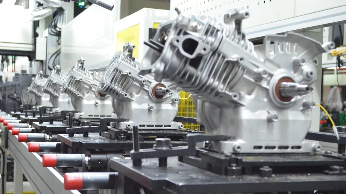
Water pump manufacturing involves a series of precise engineering, machining, assembly, and testing processes. Every component—from the pump housing and impeller to the shaft, mechanical seal, and engine—must meet defined requirements before the complete unit can deliver stable flow and pressure in the field.
For gasoline and diesel water pumps used in irrigation, drainage, construction, and water transfer, manufacturing quality directly affects flow rate, lift, fuel efficiency, vibration, durability, and operating reliability.
So, how are water pumps manufactured in a factory? The process typically covers engineering design, raw material selection, component machining, impeller manufacturing, pump and engine assembly, surface treatment, performance testing, final inspection, and packaging.
In this guide, we’ll walk through each stage of the water pump manufacturing process and explain the key quality controls used to produce reliable equipment for distributors, importers, and professional users.
What Are Water Pumps Made Of?
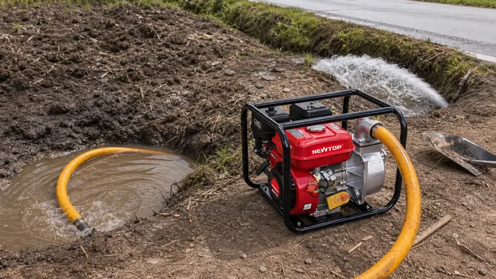
Water pump materials range from cost-effective cast iron to specialized alloys and engineered plastics, selected strictly based on fluid chemistry, system pressure, and abrasive wear conditions.
Primary Metals Used in Pump Housings and Impellers
Metal components form the main structural and hydraulic parts of most gasoline and diesel water pumps. Manufacturers select materials according to the required strength, weight, wear resistance, and operating environment.
- Cast iron: Commonly used for pump housings and impellers where strength, durability, and wear resistance are important. It is especially suitable for heavy-duty water transfer applications.
- Aluminum alloy: Widely used for portable water pump housings because it provides a good balance between strength and low weight. Reducing housing weight makes the complete pump easier to transport and handle.
- Stainless steel: Used for shafts, fasteners, and selected hydraulic components where higher corrosion resistance is required.
- Carbon steel and alloy steel: Common choices for shafts and other load-bearing components because they provide the strength needed for continuous rotation and mechanical loads.
For portable gasoline water pumps, material selection often involves balancing durability with portability. A cast-iron component may provide excellent wear resistance, while an aluminum housing can help reduce the total weight of the machine. For example, NEWTOP’s NTWP30 uses a cast-iron impeller and aluminum pump body, combining a durable rotating component with a relatively lightweight housing.
Non-Metallic Components and Sealing Materials
Metal components provide structural support, but non-metallic parts are equally important for reliable pump operation. Seals, gaskets, O-rings, and other polymer components help prevent water leakage and protect internal parts.
Common materials include:
- Ceramic and carbon: Frequently used as mechanical seal faces because they provide good wear resistance and sealing performance.
- Nitrile rubber (NBR): Commonly used for seals and O-rings in general water pump applications.
- EPDM: Offers good resistance to water, heat, and weathering and can be used in suitable sealing applications.
- PTFE: Provides strong chemical resistance and low friction, making it useful for specific sealing requirements.
The correct sealing material depends on the water temperature, fluid characteristics, shaft speed, and operating conditions. A high-quality mechanical seal is particularly important because leakage around the rotating shaft can quickly affect pump performance.
9 Steps of the Water Pump Manufacturing Process
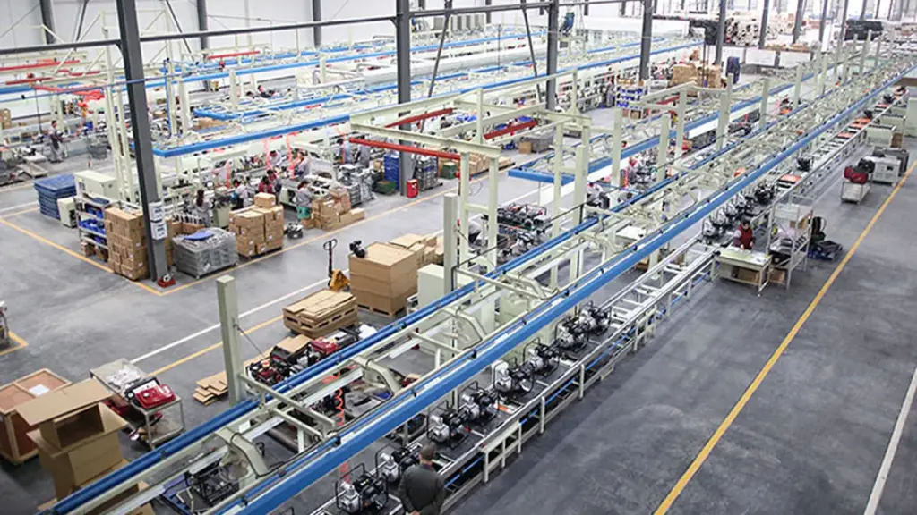
| Manufacturing Phase | Key Components Involved | Critical Quality Control Check |
|---|---|---|
| Engineering & Forming | Casing, Volute, Core Shafts | Material composition and draft geometry |
| Machining & Preparation | Housings, Shaft seats, Impellers | CNC dimensional accuracy and static balance |
| Assembly & Sealing | Bearings, Mechanical seals, Motor | Fastener torque and shaft alignment |
| Testing & Dispatch | Fully assembled pump unit | Hydraulic load testing and leak detection |
Step 1: Water Pump Design and Engineering
Engineers initiate the manufacturing cycle using advanced CAD software to establish the pump’s core geometry and performance targets. This digital blueprint dictates the physical architecture and maps out major part interfaces, which directly guides the downstream casting and machining operations.
Design teams calculate and account for critical operational variables from the start:
- Flow rate and head: Setting the baseline for hydraulic capacity.
- Fluid type: Adjusting for viscosity, corrosiveness, or abrasive solid content.
- Operating environment: Factoring in extreme ambient temperatures or submerged conditions.
Step 2: Raw Material Selection and Component Manufacturing
Factories select industrial-grade metals like cast iron, aluminum, or stainless steel based on the specific tensile strength and corrosion resistance the application demands. Foundries then form the major structural elements, including the pump body and volute, through heavy casting, forging, or smelting.
Simultaneously, specialized production lines manufacture the supporting internal mechanics. This includes:
- Drive shafts and rotors
- Stators and bearing assemblies
- Mechanical seals and gaskets
Step 3: Pump Body and Engine Component Machining
Rough castings rarely exit the mold ready for assembly. They undergo CNC precision machining to cut, drill, and face critical surfaces so they hit exact dimensional tolerances. This removes any casting flaws and guarantees a tight mechanical fit between mating parts.
Operators focus heavily on finishing essential structural points. Flawless machining is non-negotiable for housings, shaft seats, cover faces, and primary mounting surfaces to prevent future vibration or seal failure.
Step 4: Impeller and Internal Component Manufacturing
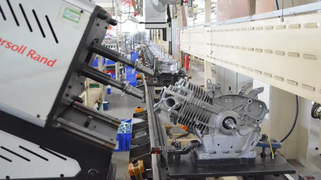
The impeller serves as the hydraulic heart of the pump. Technicians cast, machine, and precisely balance each impeller to eliminate erratic vibration and stabilize high-speed rotation. Engineers carefully optimize the impeller and diffuser geometry to maximize fluid pressure and flow output while minimizing mechanical strain.
Workers also prepare separate internal components prior to final assembly. They stage shaft pipes, balanced rotors, and wound stators so the production line maintains a steady workflow.
Step 5: Engine and Pump Assembly
Assembly lines merge the machined casing, balanced impeller, drive shaft, and prepared internals into a complete operational unit. For engine-driven configurations, technicians install and align the motor, securely fastening all heavy-duty drive components to prevent torque distortion.
This stage requires exact handling to avoid misalignment or pressure drops. Workers carefully press-fit bearings and install mechanical seals, lock nuts, and mating flanges to establish a reliable, leak-proof barrier.
Step 6: Surface Treatment and Finishing
Bare metal requires defense against harsh industrial or outdoor environments. Technicians apply specialized surface treatments like anti-rust paint, heavy powder coating, or protective enamel to shield the exterior from corrosion and physical wear.
Preparation goes beyond the exterior housing. Workers clean, dry, and apply specific pre-coats to internal cavities and bearing boxes to prevent internal degradation before the pump ever sees liquid.
Step 7: Water Pump Performance Testing
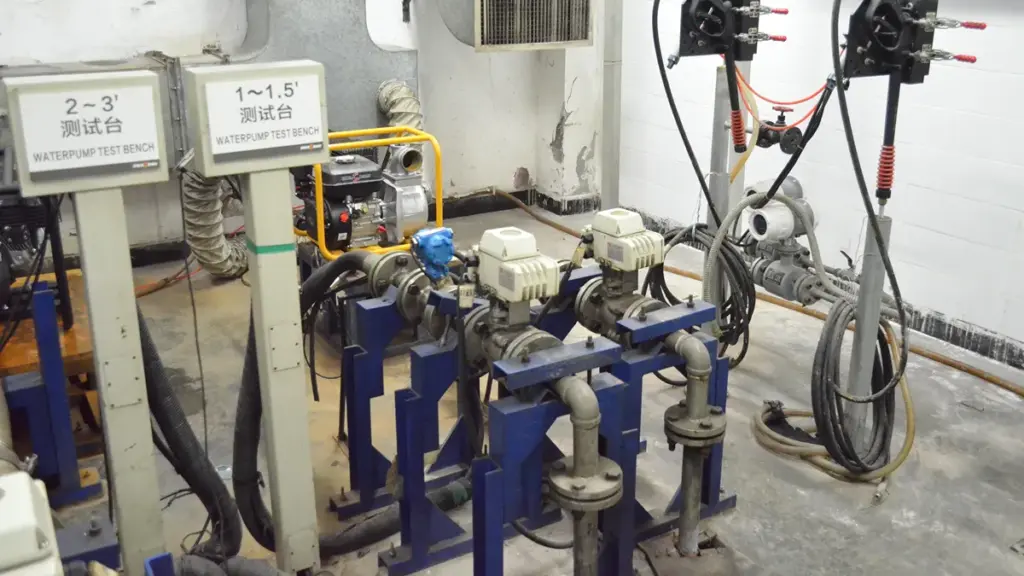
Performance testing acts as the primary proof of build quality. Technicians mount the fully assembled pump on a closed-loop hydraulic test bench and run it under load to verify it hits guaranteed operational standards.
Inspectors monitor and record these critical parameters:
- Hydraulic output: Checking exact flow rate and discharge pressure.
- Integrity: Scanning for housing leaks and seal weeping.
- Mechanics: Measuring operational noise and detecting abnormal vibration.
Step 8: Quality Control and Final Inspection
Final inspection serves as the last barrier before dispatch. Quality control teams conduct strict visual and dimensional checks, confirming the physical product aligns perfectly with the original engineering drawings. They also verify cleanliness to keep debris out of the internal fluid path.
Inspectors aggressively hunt for defects. They will catch and reject any units showing surface damage, pinhole leaks, poor shaft alignment, or uneven coating. They also validate batch tracking codes to maintain full manufacturing traceability.
Step 9: Packaging and Shipment
The factory floor cleans, labels, and securely packs the approved water pumps using impact-resistant protective materials. Proper packaging prevents transit damage during rough freight handling and long-distance hauling.
Logistics teams insert necessary accessory kits, user manuals, and final batch tracking documents into the crates. The packaged units are then dispatched to industrial users, regional distributors, or direct retail channels.
Maximize Margins With Premium Agricultural Machinery
How Does a Factory Ensure Water Pump Quality?
Factory quality assurance for water pumps is an integrated system. It combines strict incoming material checks, precision CNC machining, controlled assembly, and rigorous hydraulic testing before final shipment.
Engineering Design and Material Inspection
Quality control starts long before parts hit the production floor. Engineers use CAD and 3D modeling software to define exact pump geometry, tight tolerances, and strict performance targets. This upfront design dictates the required strength and corrosion resistance, leading to the selection of core materials like cast iron, aluminum, and stainless steel. Once the raw materials arrive, the factory conducts thorough incoming inspections. Technicians verify the chemical and physical properties of all metals, copper windings, rubber components, plastics, and seals to guarantee only approved materials enter the manufacturing line.
Casting, Molding, and Machining Controls
Structural integrity relies on highly controlled casting and molding processes. Foundries manage melting, pouring, and cooling times to prevent hidden defects like porosity or cracking in the rough casings. After casting, the components move to the machining phase. Operators use CNC machines, drills, and lathes to cut proper fits for bearings and shafts. The goal here is maintaining exact dimensional tolerances. This precision ensures correct impeller clearances, which directly prevents internal friction and maximizes hydraulic efficiency.
Motor Assembly and Verification
For electric water pumps, mechanical and electrical reliability are inseparable. Technicians focus heavily on copper winding density, precise rotor balancing, and thorough insulation resistance checks before motor integration. On the assembly line, workers install pump housings, seals, bearings, and fasteners following strict fit-up and torque control protocols. Factories set up dedicated inspection points throughout this sequence. These checks verify component alignment at every stage, preventing hidden assembly defects from moving down the line and reaching the customer.
Comprehensive Performance Testing
Performance testing acts as the primary proof of build quality. Finished units undergo rigorous evaluations on closed-loop test benches to validate their operational metrics against the original engineering targets.
- Hydraulic Performance: Technicians confirm the pump delivers the exact head, flow rate, and power consumption required by the specification.
- Pressure and Leakage: Hydrostatic tests check the casing integrity and mechanical seal effectiveness under heavy load.
- Noise and Vibration: Monitoring equipment detects abnormal running behavior caused by rotor imbalance or internal misalignment.
Final Inspection and Traceability
The last quality gate happens right before the pump leaves the factory. Quality control teams conduct final visual inspections to check surface cleanliness, correct labeling, and accurate documentation. They also verify packaging standards to reduce the risk of transit damage. Factories log every unit with batch tracking and inspection data. If a field defect occurs, the manufacturer can quickly isolate the specific production lot. This traceability extends into after-sales support, where factories analyze field performance data to refine future testing standards and engineering designs.
Looking for a Reliable Water Pump Manufacturer? Talk to NEWTOP
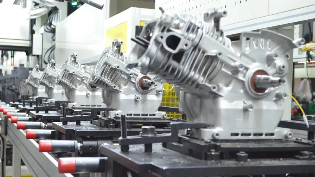
Choosing a water pump supplier means looking beyond flow rate and engine power. Consistent quality, reliable performance, and stable production are equally important for long-term business.
NEWTOP manufactures gasoline and diesel water pumps for irrigation, drainage, construction, and general water transfer. With different flow, head, and port configurations, NEWTOP can provide suitable solutions for different applications and market requirements.
If you are sourcing water pumps for wholesale, distribution, or OEM/ODM projects, talk to NEWTOP about your required specifications and order volume. Our team can help you select the right pump for your market and application.
Need a reliable water pump supplier? Contact NEWTOP today.
Frequently Asked Questions
What materials are best for water pump housings?
The choice depends on the application. Cast iron and ductile iron are standard for general-purpose pumps due to strength and cost-efficiency. Stainless steel and bronze are preferred for corrosive or marine environments, while engineering plastics like PVDF handle highly chemical-laden water.
How is ISO 9906 used in water pump manufacturing?
ISO 9906 is an international testing standard for rotodynamic pumps. Factories use it during final acceptance testing to verify that a pump meets the buyer’s guaranteed flow, total head, and power specifications within standardized tolerance grades before it leaves the facility.
What methods do factories use to test for pump leakage?
Manufacturers primarily rely on hydrostatic pressure tests, where the assembled pump is filled with water and pressurized to 1.5 times its rated working pressure. Technicians hold this pressure for several minutes to verify that the casing, joints, and mechanical seals remain completely water-tight.
How do manufacturers test the flow and pressure of a new pump?
Pumps are installed on a calibrated closed-loop test bench and run at various operating speeds. Flowmeters and pressure transducers measure the discharge flow and head at multiple duty points. This data creates a performance curve that is compared against the factory guarantee.
What final quality checks occur before a water pump is shipped?
Before dispatch, pumps undergo a rigorous end-of-line inspection. This includes visual and dimensional checks, functional performance runs, electrical safety tests for motorized units, acoustic checks for abnormal vibration, and a final verification of packaging and labeling integrity.

China is one of the world’s major manufacturing bases for portable diesel water pumps, with suppliers ranging from specialized pump factories to outdoor power equipment manufacturers offering engines, generators, sprayers, and pumps.
For importers, distributors, agricultural equipment dealers, and OEM buyers, the challenge is not simply finding a factory with a diesel water pump. The more important questions are whether the manufacturer can provide stable quality, suitable flow and head performance, reliable spare parts, export certifications, consistent production, and long-term technical support.
Based on product range, manufacturing experience, production capabilities, export focus, and publicly available product information, the following are 10 China portable water pump manufacturers worth considering in 2026.
Top 10 Diesel Portable Water Pump Manufacturers in China
Quick Comparison Overview
| Manufacturer | Location | Main Strength | Diesel Water Pump Focus | Suitable For |
|---|---|---|---|---|
| NEWTOP | China | Outdoor power equipment & OEM | Portable diesel pumps, high-flow models | Importers, distributors, OEM |
| BISON | Taizhou, Zhejiang | Power equipment | Diesel, high-pressure and cast-iron pumps | Wholesale & distributors |
| Taizhou Genour Power Machinery | Taizhou, Zhejiang | Engines, generators & pumps | Diesel and gasoline water pumps | Global dealers |
| Taizhou Newland Machinery | Taizhou, Zhejiang | High-volume pump production | Diesel water pumps | Wholesale buyers |
| Taizhou Yuhao Machinery | Taizhou, Zhejiang | Power equipment | Diesel pumps and engines | Importers & distributors |
| Taizhou Longfa Machinery | Taizhou, Zhejiang | Generators, engines & pumps | 2", 3", 4" and high-pressure pumps | Agriculture & outdoor use |
| Zhejiang Leo Garden Machinery | Wenling, Zhejiang | Garden machinery | Diesel and gasoline pumps | Garden & agricultural channels |
| Zhejiang Wenxin | Zhejiang | Agricultural equipment | Diesel and gasoline pumps | Agriculture & sprayer dealers |
| Fuan Ocean Motor | Fu’an, Fujian | Motors & pumps | Diesel engine and high-pressure pumps | Pump distributors |
| Fuan Sea Pump | Fu’an, Fujian | Pumps and power equipment | Diesel and fuel-engine pumps | Export wholesalers |
#1 NEWTOP
NEWTOP stands out as a high-volume global supplier by delivering premium component-backed diesel pumps and extensive OEM customization for emerging markets.
Founded in 2003, NEWTOP is an outdoor power equipment manufacturer with a 10,000 m² factory and annual production capacity of 500,000+ units. Its product range includes chainsaws, brush cutters, sprayers, generators, tillers, outboard motors, and water pumps.
The NTDWP30 is a 3-inch diesel water pump powered by a 4 kW NTDE178F engine, delivering up to 60 m³/h flow, 26 m head, and 8 m suction height.
Key advantages include:
- OEM/ODM support for branding, colors, packaging, and specifications
- 500,000+ units annual capacity for stable bulk supply
- 26 certifications supporting international market requirements
- Certifications include CE, ECE, EPA, Euro V, ISO 9001, and ISO 14001
- Multiple pump options, including diesel, gasoline, high-pressure, and cast-iron models
For importers and distributors seeking a reliable portable diesel water pump manufacturer with broader outdoor power equipment capabilities, NEWTOP is worth considering.
📊 At a Glance:
- 📍 Location: Shanghai, China
- 🏭 Core Strength: Diesel Water Pumps, Chainsaws, Brush Cutters, Generators
- 🌍 Key Markets: Africa, Latin America, Asia, Eastern Europe
Why We Picked Them:
| ✅ The Wins | ⚠️ Trade-offs |
|---|---|
|
|
#2 BISON
BISON excels by offering export-ready, mid-market portable pumps alongside a diverse equipment portfolio for simple one-stop sourcing.
BISON operates out of Taizhou, manufacturing a wide array of diesel water pumps and power equipment. They supply a broad range of portable, mid-market pumps spanning 2-inch to 4-inch sizes, complete with convenient electric-start options.
The company focuses heavily on factory-direct wholesale, targeting farm irrigation, emergency transfer, and utility applications. Buyers benefit from their strong focus on providing export-ready documentation to simplify global logistics.
📊 At a Glance:
- 📍 Location: Taizhou, Zhejiang, China
- 🏭 Core Strength: Diesel Water Pumps, Generators, Engines, Pressure Washers
- 🌍 Key Markets: Global
#3 Taizhou Genour Power Machinery

Genour excels at delivering compact, export-ready diesel pumps tailored for wholesale distribution and commercial irrigation.
Specializing in engine and water pump manufacturing for over 10 years, Genour offers portable diesel water pumps in 1-inch to 4-inch variants under the PowerValue brand.
They are highly active in wholesale and distribution channels, focusing on compact diesel units for commercial irrigation and construction site dewatering.
📊 At a Glance:
- 📍 Location: Taizhou, Zhejiang, China
- 🏭 Core Strength: Gasoline/Diesel Engines, Generators, Portable Water Pumps
- 🌍 Key Markets: Global
#4 Taizhou Newland Machinery

Newland excels at providing EU-compliant diesel pumps alongside a diverse equipment catalog to simplify mixed-container sourcing.
Newland manufactures multi-category equipment, supplying portable centrifugal diesel pumps like their 4-inch 10hp models.
Operating from the Taizhou manufacturing hub, the company supplies European and international markets by maintaining strict EU Stage V and CE compliance.
📊 At a Glance:
- 📍 Location: Taizhou, Zhejiang, China
- 🏭 Core Strength: Diesel Water Pumps, Generators, Air Compressors
- 🌍 Key Markets: Global
#5 Taizhou Yuhao Machinery
Yuhao Machinery excels in providing competitive pricing and flexible OEM options for bulk agricultural pump procurement.
Yuhao Machinery operates as a mid-market supplier within the Taizhou manufacturing ecosystem, focusing on portable diesel water pumps and related power equipment.
They supply irrigation and emergency dewatering pumps at competitive price points, specifically targeting B2B bulk procurement and OEM supply for the agricultural sector.
📊 At a Glance:
- 📍 Location: Taizhou, Zhejiang, China
- 🏭 Core Strength: Diesel Water Pumps, Agricultural Pumping Equipment
- 🌍 Key Markets: Global
#6 Taizhou Longfa Machinery
Longfa Machinery stands out for its high-volume production capacity of 15,000 units per month, making them an excellent fit for bulk wholesalers.
Established in 2003, Longfa Machinery manufactures portable and high-pressure diesel water pumps alongside industrial generators. They supply the agricultural and construction sectors with reliable, movable 4-inch, 10HP pumping configurations.
The factory operates with a robust output capability designed to support fast-moving supply chains. This capacity allows them to service large distributors who need consistent, high-volume equipment shipments without production bottlenecks.
📊 At a Glance:
- 📍 Location: Taizhou, Zhejiang, China
- 🏭 Core Strength: Portable Diesel Water Pumps, Generators, Power Engine Sprayers
- 🌍 Key Markets: Global
#7 Zhejiang Leo Garden Machinery
Operating under a major corporate umbrella, they excel in providing highly reliable, fully certified pumps validated by a state-authorized testing laboratory.
As part of the extensive Leo Group, this Wenling-based manufacturer builds robust diesel and gasoline engine pumps. A CNAS-recognized laboratory and rigorous quality control systems back their entire production line.
They supply fully CE-compliant portable pumps engineered for demanding agricultural and industrial water-transfer tasks. This infrastructure guarantees consistent performance for buyers scaling up their equipment sourcing.
📊 At a Glance:
- 📍 Location: Wenling, Zhejiang, China
- 🏭 Core Strength: Diesel Engine Pumps, Gasoline Water Pumps, Submersible Pumps
- 🌍 Key Markets: Global
#8 Zhejiang Wenxin Electrical and Mechanical Manufacturing
Wenxin stands out as a reliable regional partner, offering highly competitive pricing through their deep integration into the local supply chain.
Operating in the dense Zhejiang pump ecosystem, Wenxin manufactures standard portable diesel water pumps.
The company supplies mobile diesel pump sets for agricultural, municipal, and industrial water-transfer applications. This focus makes them an excellent fit for project-based sales and B2B wholesale buyers.
📊 At a Glance:
- 📍 Location: Zhejiang, China
- 🏭 Core Strength: Diesel Portable Water Pumps, Mechanical Equipment
- 🌍 Key Markets: Global
#9 Fuan Ocean Motor
Fuan Ocean Motor excels by delivering specialized high-pressure diesel pumps built for demanding irrigation and fire-support operations.
Based in the Fuan region of Fujian, Ocean Motor exports globally under the CEAN brand. They specialize in engineering high-flow and high-pressure portable diesel water pumps.
These compact, durable models routinely serve heavy-duty farm irrigation and portable fire-support scenarios. Buyers benefit from verified quality standards backed by ISO9001 and CE certifications.
📊 At a Glance:
- 📍 Location: Fuan, Fujian, China
- 🏭 Core Strength: Diesel Water Pumps, Electric Motors, Solar Pumps
- 🌍 Key Markets: Global
#10 Fuan Sea Pump

Fuan Sea Pump excels by offering premium Cummins OEM engine integration alongside top-tier international export certifications.
Fuan Sea Pump operates as a Fujian-based manufacturer and an official Cummins OEM partner. They engineer robust engine-driven water pump systems optimized specifically for construction dewatering and emergency fluid transfer tasks.
The company holds stringent CE, GS, and TUV certificates. This strict compliance profile makes their heavy-duty equipment highly viable for buyers navigating tightly regulated international markets.
📊 At a Glance:
- 📍 Location: Fuan, Fujian, China
- 🏭 Core Strength: Water Pumps, Engine-Pump Systems
- 🌍 Key Markets: Global
How to Choose the Right Diesel Water Pump Manufacturer in China
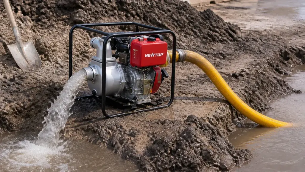
A portable diesel water pump is a complete system in which the engine, pump body, impeller, shaft, seals, frame, fuel system, and starting system all affect long-term performance.
Start with the application. Agricultural irrigation, flood drainage, construction dewatering, firefighting support, and general water transfer may require very different flow and head characteristics.
Then compare these technical points:
- Flow rate: Determine how many cubic meters per hour you actually need.
- Total head: Consider vertical lift plus pipe friction and system resistance.
- Suction height: Check the maximum practical suction distance from the water source.
- Engine power: Do not select horsepower alone; match engine output to the pump curve.
- Pump material: Cast iron is common for demanding applications, while other materials may be preferred for weight or corrosion considerations.
- Starting system: Recoil starting may suit basic portable models, while electric start can improve convenience on larger units.
- Spare parts: Confirm availability of seals, impellers, carburetion/fuel components, filters, and engine parts.
- Certification: Request certificates for the exact model and target market.
- OEM capability: Confirm whether the supplier can support your logo, colors, packaging, manuals, and product specifications.
A reliable portable water pump supplier should also provide a clear datasheet and explain the difference between maximum flow and working flow. Maximum flow is normally measured under very low resistance, while real-world performance decreases as head and pipe resistance increase.
Final Thoughts
For distributors and importers looking for a complete outdoor power equipment supply partner, NEWTOP combines diesel water pumps with a wider range of outdoor power equipment and OEM support, making it possible to build a broader product portfolio through one long-term manufacturing relationship.
Need a reliable diesel water pump for your market? Contact NEWTOP to discuss specifications, OEM requirements, MOQ, and wholesale pricing.
Frequently Asked Questions
How do I verify a water pump factory in China?
Ask for the business license, factory address, production photos or video, product catalog, quality certificates, testing records, and recent export references. A live factory video call or third-party factory audit provides stronger evidence than a supplier profile alone.
What certifications should a diesel water pump supplier have?
Common requirements may include CE, ISO 9001, EPA, EMC, GS, or market-specific environmental and safety compliance. Requirements vary by destination. Always confirm the certificate number, issuing organization, validity, and exact product model before ordering.
Can Chinese manufacturers make OEM water pumps?
Yes. Many Chinese manufacturers support OEM and private-label water pumps, including custom logos, colors, packaging, manuals, and selected specifications. NEWTOP also welcomes qualified overseas distributors and agents, offering OEM water pumps and a wider range of outdoor power equipment for long-term market cooperation.
What is the typical MOQ for portable diesel water pumps?
There is no single standard MOQ. It depends on the manufacturer, model, packaging, OEM requirements, and whether the order uses an existing product configuration. Buyers should request the MOQ for both standard orders and private-label orders separately.
How do I inspect a water pump factory before ordering?
Check raw-material control, engine and pump assembly, machining, testing equipment, finished-product inspection, warehouse management, packaging, spare-parts storage, and production records. For larger orders, an independent factory audit can provide additional assurance.
What pump tests should I request from a supplier?
Request performance testing for flow rate, total head, suction height, starting performance, continuous running, fuel consumption, vibration, noise, leakage, and engine stability. For an OEM order, it is also useful to approve a pre-production sample and define the acceptance criteria before mass production.
