


- All
- NEWTOP Customer Stories
- NEWTOP Explorer Hub
- NEWTOP Industry Insights
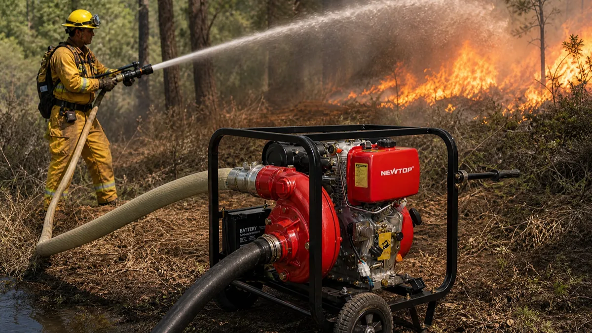
If you are sourcing a portable diesel water pump for irrigation, drainage, construction, firefighting support, or resale, price is only one part of the buying decision. Engine power, pump size, flow rate, total head, pump materials, starting system, order quantity, and customization can all affect the final cost.
In 2026, basic portable diesel water pumps from Chinese manufacturers can start at around US$130–US$180 per unit. Standard 2-inch to 4-inch models commonly range from about US$160–US$400, depending on engine power, flow rate, head, pump construction, and order quantity. High-pressure, heavy-duty, large-flow, and customized models can cost significantly more.
For distributors and OEM buyers, the key question is not simply “How much does a diesel water pump cost?” but rather “What level of flow, head, durability, and service life can I get within my target purchase price?”
How Much Does a Portable Diesel Water Pump Cost?
A practical 2026 price range for portable diesel water pumps is:
| Pump Category | Typical China Supplier Price* | Target Application |
|---|---|---|
| 2-inch standard diesel pump | US$130–US$220 | Small-scale irrigation, drainage, and general water transfer |
| 3-inch standard diesel pump | US$160–US$250 | Farm irrigation, construction drainage, and commercial water transfer |
| 3-inch high-pressure pump | US$190–US$350+ | Long-distance water transfer, uphill pumping, and high-head applications |
| 4-inch standard diesel pump | US$190–US$350 | High-volume irrigation, construction, and drainage |
| 4-inch high-flow or high-pressure pump | US$300–US$600+ | Large-volume irrigation, demanding drainage, and high-pressure applications |
| 6-inch portable diesel pump | US$190–US$600+ | Large-area irrigation, flood drainage, and high-volume water transfer |
*Prices are indicative China supplier or factory-level prices for standard configurations in 2026. Actual quotations may vary depending on engine power, flow rate, head, pump materials, starting system, MOQ, certifications, Incoterms, and OEM customization. Larger engineered, trailer-mounted, firefighting, or specialized pump systems may cost substantially more.
What Affects the Price of a Portable Diesel Water Pump?
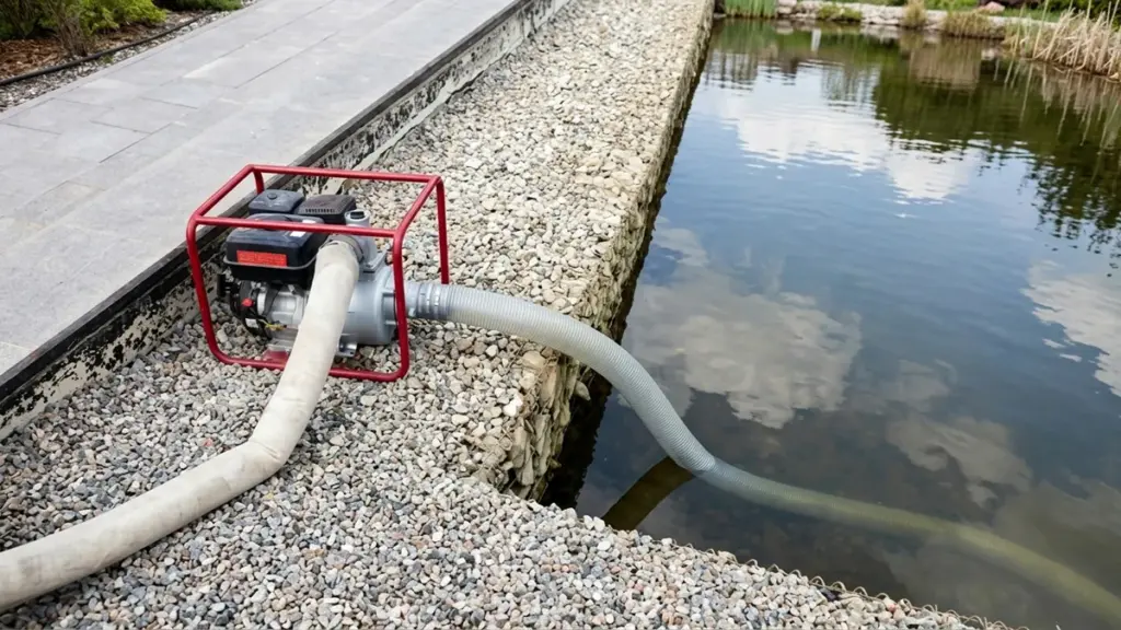
The final price of a portable diesel pump depends on discharge capacity, engine horsepower, construction materials, and whether you buy factory-direct or through a retail dealer.
Pump Capacity and Engine Performance
Flow rates and inlet diameters establish the baseline cost for any portable pump. A basic 4-inch transfer pump moves a modest volume and sits near the lower end of the pricing ladder. Step up to a 6-inch model, and manufacturers must use a larger pump housing, bigger impellers, and a heavier frame to handle the increased water volume.
Engine horsepower scales exactly with capacity. You pay progressively more to jump from a small engine to a 10 hp or 13 hp model capable of maintaining high flow rates under load. Maximum head lift also shifts the engineering requirements. Pushing water 30 meters vertical demands much higher pressure tolerances than a standard 13-meter lift, driving up the production cost.
- Discharge size: Larger 6-inch inlet/outlet diameters cost more to manufacture than standard 4-inch models.
- Horsepower: Units rated at 10 hp to 13 hp carry a higher premium than entry-level low-flow engines.
- Maximum head: High-pressure agricultural models built for steep lifts add significant engineering costs.
Build Quality, Materials, and Brand Value
Materials dictate how well a pump survives harsh environments. Standard clean-water pumps use basic alloys and keep production costs low. Trash pumps built to handle mud, slurry, and solid debris require heavy-duty cast iron, specialized seals, and corrosion-resistant materials. Upgrading these internal components immediately raises the retail price.
Brand recognition acts as a major multiplier on the invoice. Unbranded entry-level import units use standard components and keep costs close to the $225 to $300 range. Recognized retail brands charge a premium because they bundle proven durability, emissions compliance, local dealer support, and warranty coverage into the sticker price.
Starting Systems and Included Accessories
Buyers often overlook the hardware outside the pump head and engine. Manual recoil starts are cheap and standard on smaller units. Upgrading to an electric-start system requires a battery, a wiring harness, and a starter motor. This upgrade alone usually adds around $90 to the base price of a portable pump.
Add-ons dictate the final package cost. Bare pump sets offer the lowest entry point, while fully equipped packages command a premium.
- Electric start: Adds cost through required batteries, wiring, and specific starter hardware.
- Mobility kits: Robust roll frames and wheel kits for easy job site transport increase the total package price.
- Fuel tanks: Expanded fuel tanks built for long continuous runtimes add material cost.
- Bundled accessories: Specialized suction hoses, strainers, and quick-connect fittings factor heavily into the final equipment cost.
Market Channels: B2B vs. Retail Pricing
The supply chain determines the final number on the quote. B2B factory direct channels offer the lowest entry pricing. Buying straight from the manufacturer removes the middleman, making it the most cost-effective route for bulk orders or OEM purchases.
Retail storefronts price identical units higher. They must cover import duties, distribution overhead, local warehousing, and immediate after-sales support. A high-spec industrial B2B pump might land between $2,700 and $3,500 per unit direct from the factory, while a heavily branded retail model built to similar specs can reach over $22,000 MXN in local markets.
Looking for a Reliable China Diesel Water Pump Supplier?

Portable Diesel Water Pump Price by Pump Size
Pump size sets the base price tier, but engine horsepower and industrial-grade construction drastically shift the final cost within each category.
2-Inch and 3-Inch Pumps: Entry-Level and Mid-Range Pricing
Small 2-inch basic portable units form the lowest-cost segment of the market. Buyers typically find these entry-level systems priced between US$51 and US$185.
Stepping up to a 3-inch pump offers a common balance of portability and flow rate. Standard models in this size sit between US$167 and US$800. If you require higher output, upgraded engine configurations ranging from 10 HP to 15 HP will push costs toward the upper end of the US$600 to US$800 bracket.
4-Inch Pumps: The Transition to High-Output Systems
The 4-inch category represents a major step up in water-moving capacity. This performance jump requires heavier frames and stronger engines. Basic 4-inch portable agricultural pumps usually range from US$182 to over US$1,300, depending on the engine output.
Pricing escalates sharply when buyers configure these systems for heavy-duty applications. Fully equipped trailerized 4-inch trash pumps frequently cost between US$7,000 and US$15,000.
6-Inch to 12-Inch Pumps: Commercial and Industrial Systems
Standard 6-inch portable transfer pumps often list between US$300 and US$1,300 on wholesale marketplace platforms. Once you specify industrial-grade, mobile, and self-priming 6-inch units, prices start around US$2,500 to account for the robust construction.
Large 8-inch to 12-inch mobile systems serve intensive flood control or wastewater management projects. These massive units command the highest prices, ranging from US$4,800 to well over US$20,000.
Portable Diesel Water Pump Price by Flow Rate and Head
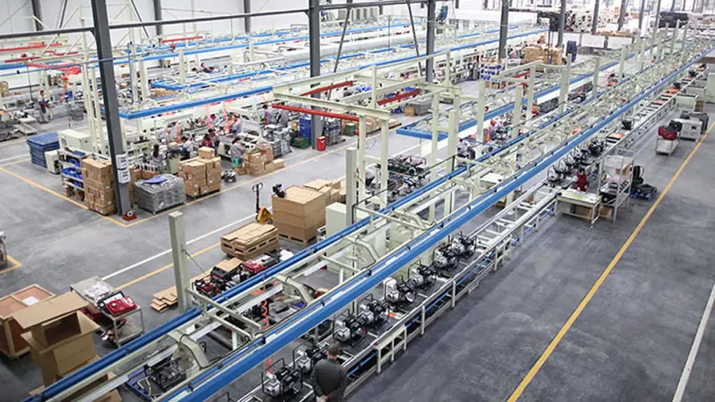
Pump capacity dictates cost, but flow rate and head height aren’t the only variables. Expect to pay more for higher horsepower engines, self-priming features, and heavy-duty towable frames.
Pricing Based on Flow Rate Capacity
How much water you need to move directly anchors your starting budget. Small-scale tasks rely on low-flow transfer pumps operating around 30 L/min, which represent the budget tier. You will typically spend between $30 and $100 for these compact units.
As you scale up to standard agricultural or construction dewatering, prices shift. Standard mid-range units, such as 3-inch pumps delivering 25 to 48 cubic meters per hour, generally range from $225 to $400. Industrial jobs require high-volume models pushing 540 GPM or 960 LPM. These heavy-duty configurations scale significantly higher, spanning from $2,000 to over $8,000.
Cost Variations Driven by Pump Head
Flow rate tells only half the story. The vertical distance you need to move that water—the pump head—forces major engineering changes. Pumps requiring higher lift capacity demand more robust engine output and stronger internal pump stages, directly increasing the final cost.
Entry-level models built for basic flat-ground transfer duty handle low head applications. These remain the most affordable options on the market. If your site requires moving water out of deep trenches or up steep inclines, you need units engineered for moderate to high lift. Pumps achieving 25 to 30 meters of head command a strict premium over standard transfer equipment.
Combined Impact of Engine Size and Pump Type
Pumping specs do not exist in a vacuum. A 3-inch pump with a basic engine costs vastly different than a 3-inch pump built for raw site work. Several specific hardware and purchasing variables dictate the final invoice.
- Engine Horsepower: Flow rate alone does not dictate price. Engine size plays a major role, with 13 HP models costing substantially more than 5 HP alternatives built for the same pipe diameter.
- Specialized Configurations: Adding self-priming mechanisms, trash-handling capabilities, and towable highway frames adds significant cost to the base unit.
- Order Volume: Purchasing volume immediately alters the pricing structure. Wholesale B2B orders lower the per-piece rate heavily compared to single-unit retail listings.
Buyers must lock down their exact engine and frame requirements before comparing quotes, or they risk matching a cheap transfer pump against a commercial trash unit.
Diesel vs Gasoline Water Pump: Which Costs More?
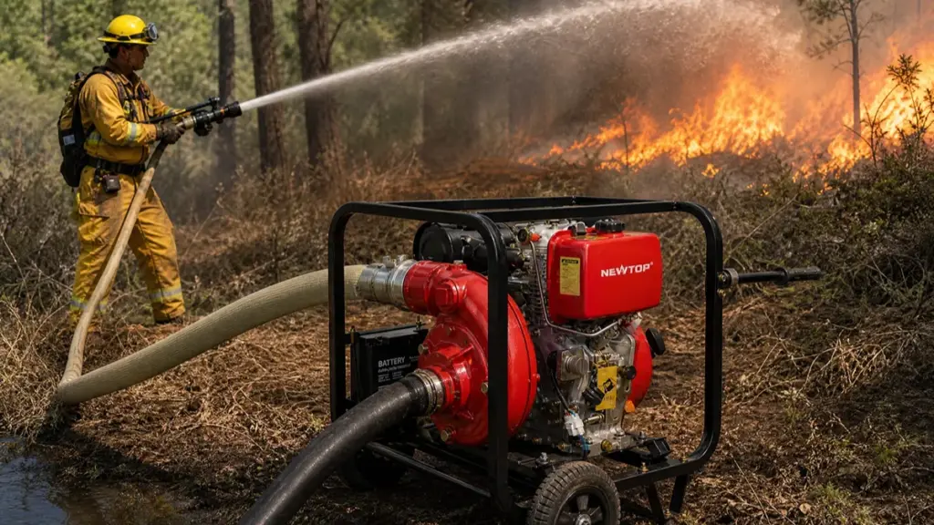
Diesel water pumps cost more upfront than gasoline models due to heavy-duty engineering, but their durability offsets replacement costs in continuous, rugged applications.
Initial Purchase Price Differences
Gasoline-powered portable pumps generally offer the lowest upfront purchase cost in the market. When you compare units in the exact same size and performance tier, diesel water pumps demand a higher initial investment.
Retail data and supplier listings consistently place gasoline units in lower-cost entry tiers. Manufacturers build gas models for lighter duty cycles, keeping raw material and production costs low compared to equivalent diesel packages.
Current Price Bands for Diesel Models
Diesel unit pricing scales heavily based on flow capacity, engine horsepower, and structural features.
- Entry-level small diesel pumps: US$137 to US$369
- Mid-range portable models (2-inch to 6-inch self-priming units): US$253 to US$500
- Heavy-duty industrial diesel systems (high-horsepower engines): US$1,280 up to US$20,900 or more
Manufacturing Factors Driving Diesel Costs
The price gap between diesel and gasoline comes directly from engineering requirements and the intended operating environment.
- Engine construction: Compression-ignition diesel engines demand stronger, heavier materials to safely handle higher internal pressures.
- Hardware upgrades: Manufacturers often equip diesel pumps with heavy-duty frames, wheel kits, and trash-handling components built for demanding environments.
- Complete systems: Package configurations, including trailers and specialized hoses, add significantly to the total unit price.
Matching Budget to Application Needs
Gasoline pumps suit buyers prioritizing immediate cost savings and intermittent operation. They work well for fast, temporary water transfer jobs where the equipment sits idle for long periods between uses.
Diesel units serve applications requiring continuous runtime, high-volume flow, and proven reliability in remote locations. The higher purchase price of diesel systems directly offsets long-term replacement costs in rugged agricultural or commercial construction settings.
What Is Included in the Price of a Diesel Water Pump?
Before accepting a quotation, confirm exactly what the supplier’s price includes.
A standard factory quotation may include the diesel engine, pump body, frame, fuel tank, basic controls, inlet/outlet fittings, and standard packaging. However, accessories such as hoses, strainers, couplings, wheels, electric-start batteries, or special connectors may be optional.
You should also confirm whether the quoted price includes:
- Standard spare parts
- Warranty
- User manual
- Product testing
- Export packaging
- Logo or label
- Certification documents
- Replacement parts
- Shipping costs
For international buyers, the difference between EXW, FOB, CIF, and other trade terms can also significantly change the final landed cost.
OEM and Custom Portable Diesel Water Pump Costs
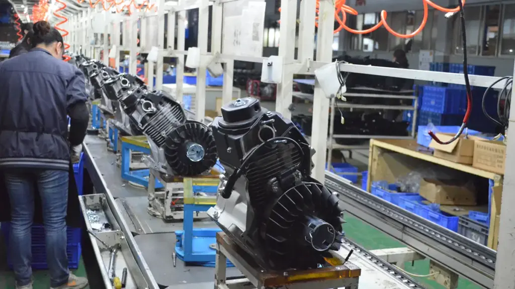
OEM pricing depends heavily on what is being customized.
Simple customization, such as a brand logo, color, label, carton design, or nameplate, normally adds less cost than changing the pump’s engineering.
More complex OEM requirements may include:
- Different diesel engine
- Electric-start configuration
- Special pump body
- Different inlet/outlet size
- Higher head or flow requirement
- Customized frame
- Special fuel tank
- Market-specific certification
- Customized packaging
For distributors, it is usually better to provide the manufacturer with a complete specification before asking for an OEM quotation. This avoids receiving a low initial price that later increases because of additional components.
MOQ also matters. A water pumps factory may offer a lower unit price for 100 or 500 units than for a trial order of 10 units. Current China supplier listings show MOQs ranging from one piece to 50 pieces or more depending on the supplier and model.
How to Get the Best Price From a China Water Pump Manufacturer
To get the best price from a China water pump manufacturer, lock in exact specifications, stick to standard configurations, and leverage larger order volumes to reduce per-unit costs.
Request Quotes Using Identical Specifications
Ambiguous requests lead to distorted pricing. If you ask five suppliers for a quote on a 3-inch pump, you will receive five vastly different numbers unless you define the exact mechanical parameters.
- Base mechanics: Compare pricing using the exact same pump size, engine horsepower, and start type to ensure accuracy.
- Physical build: Ensure frame style, wheel configuration, and self-priming capabilities match across all supplier quotes.
- Equipment class: Avoid comparing standard 2-inch or 4-inch agricultural models with high-capacity industrial dewatering pumps.
Leverage Order Volume and Standard Configurations
Factories optimize for production efficiency. Every time you change a color or request a non-standard engine brand, the manufacturer passes that setup cost directly back to you.
- Scale the MOQ: Increase the Minimum Order Quantity (MOQ) to batch, pallet, or carton sizes to secure a lower per-unit cost.
- Reject custom upgrades: Stick to standard factory configurations, as custom colors, specific engine brands, or upgraded branding usually raise the price.
- Negotiate total value: Negotiate based on the total order value and packaging simplifications rather than focusing strictly on the single-unit price.
Clarify Shipping Terms and Included Accessories
A low headline price often hides missing components or excludes freight entirely. You must strip away the ambiguity to uncover the true landed cost of the equipment.
- Isolate logistics: Ask suppliers to separate EXW, FOB (e.g., FOB Tianjin), and CIF pricing to calculate accurate landed costs.
- Confirm the bundle: Verify exactly what is included in the unit price, such as inlet/outlet fittings, wheels, or an electric start system.
- Account for adders: Account for common cost adders upfront; for example, an electric start on a 2-inch model typically adds about US$90.
Cross-Check Factory Sourcing Channels
Real manufacturers display stable pricing strategies. You can filter out trading companies and middlemen by observing how a supplier prices their equipment across the open market.
- Platform check: Compare the same pump class across multiple platforms like Alibaba, Made-in-China, and direct factory websites.
- Pricing consistency: Look for suppliers that maintain consistent, stable pricing across different marketplaces, indicating a reliable direct manufacturer.
- Quote transparency: Target transparent factory or FOB quotes rather than vague listings that obscure the base price.
NEWTOP Portable Diesel Water Pumps
NEWTOP portable diesel water pumps operate in the low-cost import segment, providing budget-friendly utility and agricultural transfer options positioned below premium industrial brands.
NEWTOP offers a range of diesel water pumps designed for agricultural irrigation, drainage, construction, emergency pumping, and other outdoor applications.
The NTDWP30 is a 3-inch diesel water pump powered by a 4 kW NTDE178F diesel engine. It combines a precision-machined pump body, 42CrMo forged crankshaft, BOSCH-technology fuel injection, nitrided gears, and a full-frame vibration-control structure.
For higher-volume applications, the NTDWP40 delivers up to 96 m³/h with a 6.3 kW diesel engine, while the NTDWP60 reaches up to 150 m³/h with an 8.5 kW engine.
This range allows distributors and equipment buyers to select a pump according to the actual combination of flow, head, engine power, and application, rather than choosing by pump size alone.
If you are planning an OEM order, NEWTOP can also discuss model selection, specifications, packaging, branding, and quantity requirements before quotation.
Looking for a reliable portable diesel water pump supplier for your market? Contact NEWTOP with your required pump size, flow, head, application, and order quantity to receive a model recommendation and quotation.
Frequently Asked Questions
How much does a portable diesel water pump cost?
A portable diesel water pump from a China manufacturer can typically cost around US$120–US$400+, depending on size, engine power, flow, head, materials, and order quantity. Larger high-flow and high-pressure models can cost more.
Are diesel water pumps more expensive than gasoline pumps?
Usually, yes. Diesel pumps generally have a higher purchase price because of their engine construction and heavy-duty design. However, they may offer better fuel efficiency and durability for frequent or demanding operation.
What size diesel water pump do I need?
Select a 2-inch pump for light water transfer, a 3-inch model for balanced portability and throughput, or a 4-inch pump for construction dewatering. You must match the pump size directly to your required flow rate and total vertical lift.
How long will a diesel water pump run on one tank?
Runtime varies based on fuel tank capacity, engine load, and pump size. Small portable models run for several hours on a standard tank, whereas heavy-duty mobile pump stations with large fuel tanks can operate continuously for up to 48 hours.
What affects the price of a diesel water pump?
Pricing primarily depends on engine horsepower, flow capacity, and maximum head pressure. Additional features like electric start systems, self-priming capabilities, and trailer mounts also significantly increase the final cost.
Is a diesel water pump worth the extra cost?
A diesel water pump provides excellent value if you need high flow rates, extended continuous operation, or reliable power in remote areas. A cheaper gasoline or electric pump makes more sense for occasional light-duty home drainage.
What is the MOQ for OEM diesel water pumps?
Most suppliers offer a minimum order quantity (MOQ) of 1 to 10 pieces for standard OEM diesel water pumps. Custom manufacturing runs or deeply discounted bulk orders typically require MOQs of 50 to 100 units.
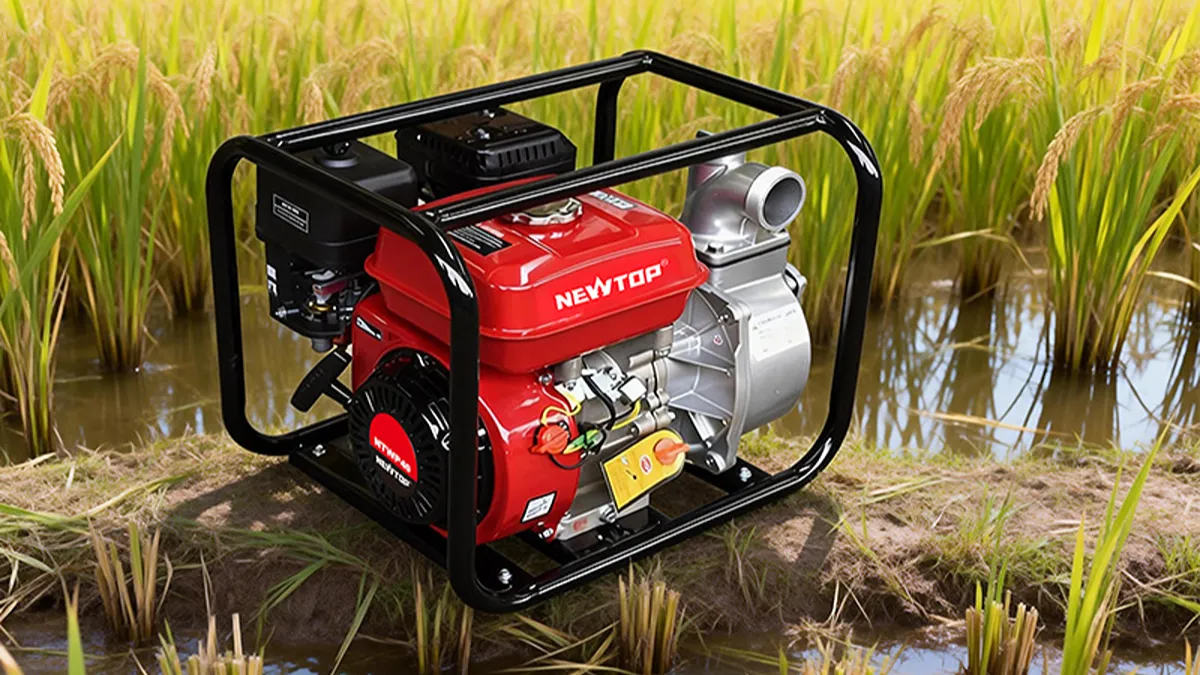
Water pumps are designed for different working conditions, and the right choice depends on how the water needs to be delivered. A high pressure water pump is designed to provide higher head for applications such as uphill irrigation, long-distance water delivery, and sprinkler systems. A general purpose water pump is typically selected for moving larger volumes of water in applications such as drainage, construction, and general irrigation.
The difference becomes clearer when you look at two key pump specifications: flow rate and head. Understanding how these two values affect pump performance can help you select the right water pump for your application, avoid insufficient pressure or flow, and get more reliable performance in the field.
What Is a High Pressure Water Pump?
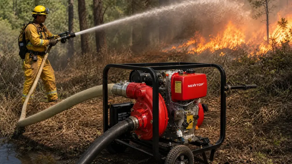
A high pressure water pump generates forceful head rather than sheer volume. It pushes water against gravity, long distances, or high-resistance nozzles to perform physical work.
Core Definition and Purpose
A high pressure water pump is designed to generate a higher head, allowing water to overcome greater resistance in the discharge system. This makes it useful when water must travel a long distance, move uphill, or pass through smaller pipes, sprinklers, or other restrictive equipment.
Common Pump Types for High Pressure
Manufacturers build several distinct pump configurations to handle elevated pressure demands across different industrial and agricultural sectors.
- Centrifugal high-pressure pumps: Frequently configured for demanding water-transfer tasks and large-scale agricultural irrigation systems.
- Positive displacement pumps: Capable of producing significantly higher pressures and operating with extreme efficiency during continuous, demanding duties.
- Multi-stage pumps: Utilize multiple internal impellers to generate and sustain higher head, commonly found in heavy industrial applications.
Typical Applications and Use Cases
Any application requiring water to act as a physical tool or travel against heavy mechanical resistance demands a high pressure setup.
- Agriculture: Powering large irrigation sprinklers and managing consistent long-distance water delivery across uneven terrain.
- Cleaning: Supplying steady, forceful streams for commercial pressure washing, surface preparation, and heavy industrial washdowns.
- Fire suppression: Delivering emergency water streams safely and effectively over distances to reach active hazards.
- Industrial processing: Handling internal tasks like deep well water injection, machinery descaling, and high-pressure boiler feed operations.
What Is a General Purpose Water Pump?
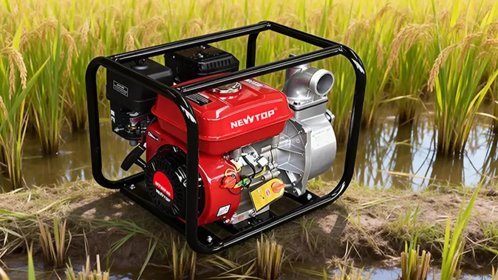
A general-purpose water pump handles routine liquid transfer, prioritizing a practical balance of flow, head, and cost rather than specialized extreme-duty performance.
Core Definition and Function
A general purpose water pump is typically designed to move water efficiently rather than generate maximum pressure. These pumps are commonly used for irrigation, drainage, water transfer, construction sites, ponds, tanks, and other everyday pumping tasks.
Water pumps can also be classified by how they handle air during startup. If you are comparing pump designs for different installation conditions, it is useful to understand the difference between centrifugal and self-priming pumps. Centrifugal vs Self-Priming Water Pump explains how these two pump types differ in priming requirements, startup performance, and typical applications.
Primary Applications
You will find general-purpose units operating across multiple sectors where steady volume matters more than extreme discharge force.
- Commercial and municipal: Handles building water supply, baseline pressure boosting, and HVAC chilled-water circulation.
- Agricultural and construction: Supports field irrigation, bulk water transfer, and site dewatering operations.
- Industrial and wastewater: Manages light-duty process water movement and solid-handling sewage tasks when configured properly.
Industry Standards and Compliance
Broad applicability requires strict adherence to standardized manufacturing and testing protocols. This ensures buyers can swap out units across different brands without redesigning entire piping systems.
- Hydraulic Institute (HI): Sets the baseline guidelines for nomenclature, design specifications, and performance testing.
- ISO and ANSI: Dictate dimensional standards to guarantee broad equipment interchangeability across global markets.
- AWWA and UL 778: Provide evaluation frameworks for electrical safety, operational reliability, and public water system compliance.
Boost Margins With Reliable OEM Power Equipment
High Pressure Water Pump vs General Purpose Water Pump: Key Differences
The main difference is the balance between head and flow. In simple terms, a high pressure water pump is designed to push water farther and higher, while a general purpose water pump is designed to move larger volumes of water efficiently.
| Feature | High Pressure Water Pump | General Purpose Water Pump |
|---|---|---|
| Main purpose | Overcome high resistance and lift water higher | Move large volumes of water efficiently |
| Head | Higher | Moderate |
| Flow rate | Often moderate | Often higher |
| Typical applications | Sprinklers, long hoses, uphill pumping, irrigation systems | Drainage, flood control, water transfer, general irrigation |
| Discharge system | Suitable for longer or more restrictive systems | Best for shorter, less restrictive systems |
| Priority | Pressure/head | Water volume/flow |
| Typical fuel options | Gasoline or diesel | Gasoline or diesel |
| Best selection factor | Required head and system resistance | Required flow and total head |
Flow Rate vs Head: Understanding the Main Difference
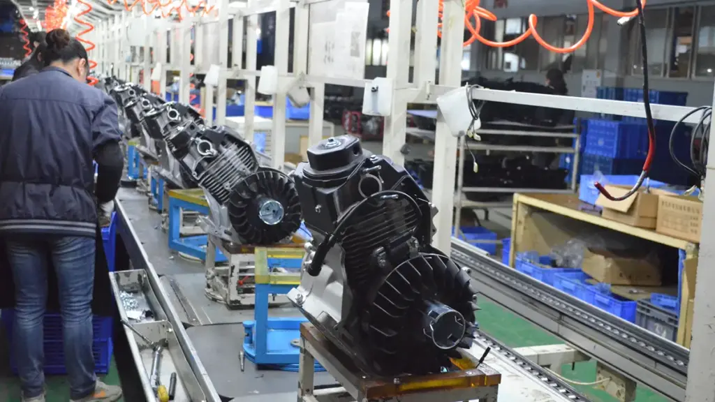
Flow rate is the volume of water moved, while head is the resistance it overcomes. Higher head limits flow, dictating actual pump performance in real-world systems.
Flow rate describes how much water the pump can move over a period of time. It is commonly measured in m³/h (cubic meters per hour) or L/min (liters per minute).
The Tradeoff Between Pressure and Volume
A pump’s flow rate is not a constant value. It decreases as the resistance it works against increases. Higher head requirements generally result in a lower flow rate at a given operating point.
This tradeoff dictates equipment selection across different applications. High-pressure water pumps prioritize head to achieve longer discharge distances and overcome extreme resistance. General-purpose models take the opposite approach, focusing on maximizing flow for basic transfer tasks where lift and friction stay low.
How System Head Affects Actual Output
System head calculates the total resistance your equipment faces in the field. This calculation combines static elevation lift, dynamic energy, and friction losses. As flow increases, friction losses from pipes, valves, and bends also increase, which restricts the delivered volume.
The true operating point occurs exactly where the pump performance curve intersects the specific system head curve. This intersection represents the actual volume the pump will deliver in a live installation, completely overriding theoretical maximums.
Practical Selection Guidelines
Selecting the right equipment requires matching your primary specification to the actual site demands.
- Prioritize head: Choose this path for applications requiring long vertical lifts, extended horizontal pipe runs, or high discharge pressure.
- Prioritize flow rate: Focus here when moving large volumes of water quickly with minimal elevation changes.
- Avoid the free-flow trap: Never buy a pump based solely on its maximum free-flow rating at zero head. Real-world resistance will lower the actual output on site.
When Should You Use a High Pressure Water Pump?
Use a high-pressure pump when you need force, not just volume. If your system requires pushing water upward, spraying, or overcoming resistance, standard transfer pumps will fall short.
Common Scenarios Requiring a Pressure Boost
High-pressure pumps step in when gravity and friction work against your water supply. A standard utility pump handles basic flow, but you need a dedicated pressure boost when fixtures fail to operate correctly due to low force.
- Low municipal pressure: Fixes weak incoming flow at taps, showers, and household appliances.
- Vertical lift: Pushes water upward to elevated fixtures, higher floors, or rooftop tanks in multi-story buildings.
- Simultaneous demand: Prevents noticeable pressure drops when multiple outlets, such as a shower and a washing machine, run at the same time.
Specific Applications and Setups
Beyond basic household plumbing, specific mechanical setups demand high pressure to function. You need a pump built to handle resistance and maintain a usable discharge pressure all the way to the end of the line.
- Underground sources: Drawing supply from shallow wells, underground cisterns, or buried storage tanks where self-priming is necessary.
- Sprinkler networks: Operating pressure-dependent irrigation systems that require a steady, forceful supply to achieve the correct spray reach.
- Line supplementation: Acting as a compact domestic booster to supplement an existing utility line without replacing the entire supply system.
When to Avoid High-Pressure Pumps
Higher pressure is not a universal fix. Forcing a high-pressure unit into the wrong application wastes energy, damages pipe fittings, and creates unnecessary maintenance costs. Know when to stick to a general-purpose model.
- Bulk transfer: Moving large volumes of water quickly. A standard centrifugal or high-flow transfer pump handles this much more efficiently.
- Deep source extraction: Pulling water from deep underground requires specialized deep-well or submersible pumps, not surface-mounted pressure models.
- Contaminated fluids: Pumping dirty water or liquid with heavy sediment will destroy high-pressure seals. Standard pressure pumps are built specifically for clean water applications.
Key Selection Criteria
Buying the right pump means matching its performance curve to your exact system requirements. Never size a pump based on a single metric like horsepower or maximum flow.
- Flow and force balance: Evaluating pressure and flow rate together to ensure the pump supports both the force needed and the volume for simultaneous users.
- Total vertical lift: Calculating the exact height from the pump installation level to the highest water fixture in the system.
- Intake limits: Checking the suction depth requirements if you draw water from a below-ground source.
- System controls: Selecting the right control mode, such as automatic start/stop or constant-pressure drives, to ensure consistent household comfort.
When Is a General Purpose Water Pump a Better Choice?
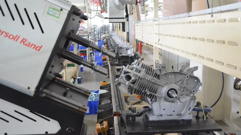
Choose a general-purpose pump when moving large volumes of water efficiently matters more than extreme discharge pressure. It cuts unnecessary costs and simplifies system maintenance.
Moderate Pressure and High Flow Requirements
General purpose centrifugal pumps thrive in environments operating well below 300 psi. Equipment following standards like ANSI/ASME B73.1 focuses entirely on efficient liquid movement. Instead of generating extreme outlet force, these units prioritize raw volume and steady transfer rates.
You should deploy them for clean or lightly treated water. They are not built for hazardous, high-temperature, or highly specialized industrial fluids. When your primary goal is shifting liquid from point A to point B without battling extreme pipe resistance, standard utility pumps handle the workload perfectly.
Ideal Applications and Use Cases
These pumps fit naturally into everyday fluid movement scenarios. Engineers specify them across commercial and industrial sites where volume throughput dictates system success.
- Water transfer: Moving liquid between tanks, reservoirs, or different process stages.
- HVAC and circulation: Running cooling or heating loops that need stable, dependable flow rather than extreme discharge pressure.
- Standard irrigation: Handling open-field or landscape watering where specialized high-pressure nozzles are absent.
- Utility services: Managing routine wastewater and general industrial facility water needs.
Cost and Maintenance Advantages
Specifying a general purpose pump keeps capital expenditure grounded. You avoid the premium price tags attached to high-pressure components and specialized industrial ratings that your system simply does not need.
This approach streamlines the specification process and removes the risk of overdesigning a basic utility setup. Because these units integrate perfectly with standard piping and normal system pressures, your team faces significantly less maintenance complexity over the equipment’s lifespan.
Situations That Require High-Pressure Alternatives
While versatile, standard transfer pumps fail under heavy resistance. You must step up to specialized equipment when the job demands sheer force rather than simple volume.
- Industrial cleaning: Standard models cannot support water jetting or hydrotesting that demands sustained pressure from 500 to over 1,500 psi.
- Fire protection: Emergency systems require certified, instant-on performance and massive lift that general utility models cannot guarantee.
- Critical process loads: Avoid standard models for demanding processes that require API-level construction to survive extreme operational stress.
High Pressure vs General Purpose Water Pump for Irrigation
Choose a high-pressure pump to push water across long distances and uneven terrain. Rely on a general-purpose pump to move large volumes efficiently for standard, flat-field irrigation.
Core Differences in Pressure and Flow
A high-pressure pump generates strong discharge pressure to overcome significant friction or elevation losses. This design inherently delivers lower flow rates. General-purpose centrifugal pumps prioritize moving large volumes of water efficiently at moderate pressures. In agricultural settings, these units commonly operate in the 15 to 60 psi range.
Upgrading to a high-pressure system introduces greater physical stress to your infrastructure. The added force places higher demands on your entire irrigation network. You must specify stronger pipes, heavy-duty fittings, and premium seals to prevent leaks or blowouts under load.
Ideal Use Cases and Applications
Matching the pump to the field layout dictates your system’s reliability. High-pressure pumps handle demanding environments where resistance restricts water delivery, especially when running pressure-compensating drip networks that require sustained inlet pressure for multiple active emitters.
Deploy a high-pressure pump for these challenging layouts:
- Long-distance conveyance: Pushing water through extensive pipe networks.
- Uneven hillside fields: Overcoming steep elevation changes.
- Filtration-heavy setups: Forcing water through restrictive filter media.
General-purpose pumps excel in straightforward, low-resistance layouts. Rely on them for:
- Surface irrigation: Flooding fields or feeding low-head systems.
- Standard field watering: Moving water across flat, accessible crop rows.
- Short-distance transfer: Pumping directly from holding tanks or nearby canals.
Operational Trade-offs and System Impact
High-pressure models successfully maintain uniform emitter performance across difficult terrain. The direct trade-off is heavy energy consumption. Forcing water at high pressures requires significantly more power, driving up your daily operating expenses.
General-purpose pumps offer a more economical solution for standard water movement. They feature lower installation costs and run much cheaper over a long growing season.
You should never oversize pressure unnecessarily. Installing a high-pressure unit on a low-resistance field leads to increased energy bills, premature component wear, and a much higher risk of pipe failure.
Key Sizing and Selection Criteria
Your selection must map directly to the required pressure at the point of use, specifically the sprinkler or emitter inlet. You cannot buy an irrigation pump based on horsepower alone.
To size the system correctly, calculate the total dynamic head (TDH). This requires combining several specific system losses:
- Static lift: The vertical distance from the water source to the pump.
- Pipe friction: The resistance created by water moving through the pipe diameter.
- Elevation changes: The vertical rise from the pump to the highest irrigation point.
- Filter losses: The pressure drop caused by screens or media filters.
- Required nozzle pressure: The exact operating pressure your sprinklers or emitters need.
Once you calculate the total dynamic head, compare these system demands against the manufacturer’s pump curve. This ensures the pump operates within its most efficient range at your target duty point.
High Pressure vs General Purpose Water Pump for Drainage and Construction
Choose general-purpose pumps to quickly move large volumes of accumulating water. Reserve high-pressure pumps for tasks demanding concentrated force, like site cleaning or overcoming extreme pipe resistance.
Core Differences: Pressure vs. Volume
The primary distinction between these two equipment categories comes down to how they handle water. High-pressure water pumps focus on generating maximum force and high discharge head. In industrial construction, they frequently operate above 500 psi using multi-stage or plunger designs.
General-purpose water pumps prioritize moving high volumes of water efficiently at modest pressures. Manufacturers typically rely on centrifugal or submersible designs for these tasks. The flow profile differs significantly based on the pump’s internal mechanics.
- High-pressure systems: Deliver lower flow rates at significantly higher pressure.
- General-purpose systems: Move high flow rates at much lower pressure.
The type of water being pumped is also important. Clean water and water containing sand, mud, leaves, or other solid particles can require different pump designs. If you need to choose between pumps for clean or contaminated water, see Trash Pump vs Clean Water Pump for a detailed comparison of their construction, handling capacity, and suitable applications.
Drainage Applications: When Flow Rates Matter Most
Site drainage success depends heavily on clearing water faster than it accumulates. General-purpose pumps are the standard choice for floodwater removal, trench dewatering, and emptying excavation pits. In these scenarios, the priority is moving massive volumes quickly.
Actual drainage performance depends primarily on the flow rate and the total dynamic head rather than raw pressure output. A pump rated for extreme pressure will underperform if it lacks the capacity to process hundreds of gallons per minute.
You only need high-pressure pumps for drainage when the site forces you to overcome specific system resistance. Common examples include pushing water through exceptionally long discharge lines or pumping it up steep vertical elevations where a standard centrifugal pump would stall.
Construction Use Cases: Dewatering vs. Site Cleaning
Construction sites demand different equipment for different phases of the project. Standard dewatering, temporary bypass pumping, and stormwater management rely on general-purpose pumps designed for high throughput and muddy water handling.
Other site activities require concentrated water force rather than simple volume transfer. You need a high-pressure pump for specific, force-driven workloads.
- Equipment washdown: Blasting dried mud and grease from heavy machinery.
- Concrete cleanup: Preparing surfaces and removing slurry.
- Hydroblasting: Stripping materials or cutting surfaces.
- Dust suppression: Forcing water through misting nozzles.
Contractors often deploy both pump types simultaneously on complex sites. Pressure-oriented and flow-oriented designs are optimized for entirely different tasks, making a single pump highly inefficient for both jobs.
Practical Selection Rules and Trade-Offs
General-purpose pumps offer simpler site deployment and better economy for routine water transfer. They run cheaper and require less maintenance, but they struggle immediately if the application demands strong outlet pressure.
High-pressure pumps easily overcome pipeline resistance and deliver aggressive cleaning power. The trade-off is their cost. They require larger capital investment, demand careful setup, and operate far less efficiently for simple volume dewatering.
The baseline rule for site use is matching the pump exactly to the primary problem. Use flow-focused equipment to remove accumulating water. Use pressure-focused equipment to perform physical work at the discharge point.
How to Choose Between a High Pressure and General Purpose Water Pump
Choose a high-pressure pump to force water through restrictions or up steep elevations, and a general-purpose pump to move large volumes quickly at a lower cost.
Core Technical Differences: Pressure vs. Flow
High-pressure models generate intense force, typically ranging from 100 psi to over 40,000 psi, to push water through system restrictions. General-purpose pumps operate at lower pressures, usually between 10 and 100 psi, prioritizing the rapid movement of large water volumes. Pressure and flow share an inverse relationship. Optimizing a pump for high pressure generally reduces its overall flow rate.
Matching the Pump to Your Application
Buyers must assess whether the water needs to do work at the outlet or simply relocate. Select a high-pressure pump for tasks demanding force, such as operating sprinklers, executing industrial wash-downs, firefighting, or pushing water up steep elevations. Choose a general-purpose pump for moving water efficiently from point A to point B. This includes draining flooded areas, filling pools, or handling basic household water transfer.
Critical Performance Factors to Evaluate
Identifying the correct pump requires matching equipment capabilities against specific site conditions.
- Discharge pressure and total dynamic head: Verify the pump can overcome specific elevation changes and pipe friction.
- Target flow rate: Match the output directly to the volume requirements of the specific task.
- Fluid quality: Identify debris levels, as contaminated water requires specialized handling designs rather than standard clean-water pumps.
- Power source: Favor engine-driven pumps for off-grid portability and electric models for stationary setups.
Cost, Energy, and Maintenance Trade-offs
General-purpose pumps require smaller motors, making them highly energy-efficient and less expensive to purchase upfront. High-pressure pumps utilize robust, precision-engineered materials to withstand operational stress. This specialized construction leads to higher initial costs and greater energy consumption. The complexity of high-pressure systems also results in a more demanding maintenance schedule compared to standard transfer pumps.
Common Selection Mistakes to Avoid
Failing to align pump specifications with the main operational goal leads to system failures and wasted capital.
- Using a high-pressure pump for simple transfer jobs: This wastes electrical or fuel energy and reduces flow efficiency.
- Underestimating pressure requirements: System performance drops rapidly when buyers ignore friction from spray nozzles, long hose runs, or restrictive fittings.
- Over-specifying specifications: Ensure the chosen pump aligns strictly with the primary objective rather than chasing unnecessary maximum ratings.
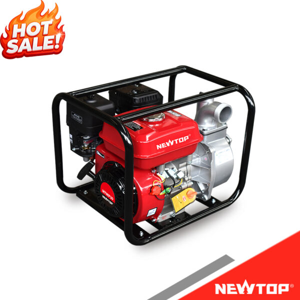
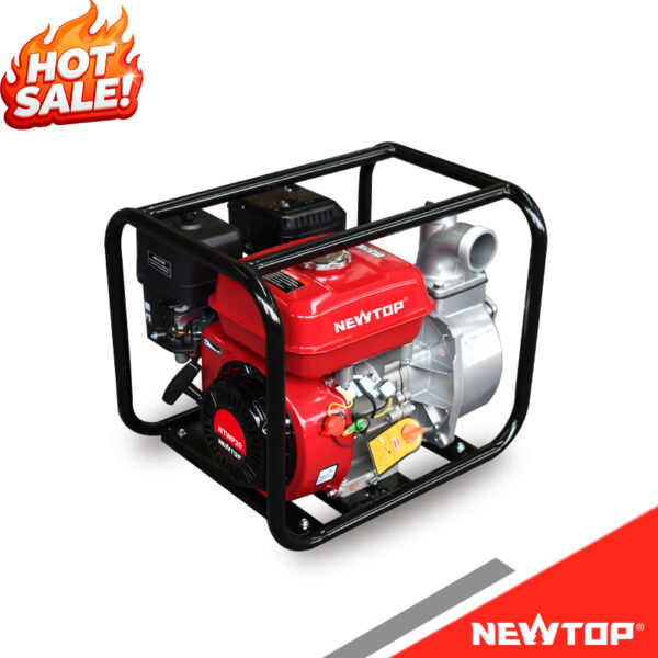
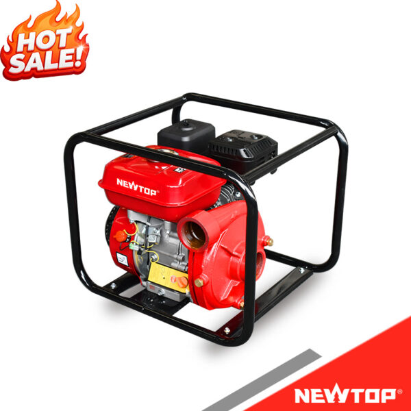
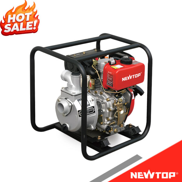
NEWTOP Water Pump Options for Different Applications
Frequently Asked Questions
What is the difference between a high-pressure and a general-purpose water pump?
A high-pressure water pump generates strong discharge force (head) designed for pressure washing, water jetting, and industrial cleaning. A general-purpose pump focuses on moving large volumes of water (flow) at lower pressures, making it the practical choice for basic fluid transfer, irrigation, and drainage.
Is a high-pressure pump better than a standard water pump?
It depends entirely on your application. A high-pressure pump is essential when a specific job demands forceful output at the discharge point, like hydroblasting or firefighting. If your goal is simply to transfer or circulate water efficiently, a standard pump is more practical and cost-effective.
Can I use a high-pressure pump for irrigation?
Yes, but reserve high-pressure pumps for large-scale or technical setups that must push water over long distances, up steep elevations, or through complex filtration systems. For a typical garden or low-resistance irrigation layout, a standard centrifugal pump provides a better balance of flow and moderate pressure.
What water pump is best for sprinklers?
Sprinkler systems require a specific balance of pressure and flow to maintain consistent spray coverage. A high-pressure centrifugal pump works best for demanding, multi-head layouts. For simpler setups, a surface booster pump handles shallow water sources well, while a submersible irrigation pump is the standard choice for accessing deeper wells.
Does higher pressure mean higher water flow?
No. Pressure is the force pushing the water, and flow is the total volume moved. In pump design, these factors generally have an inverse relationship. High-pressure units deliver lower flow rates optimized for forceful output. Standard general-purpose pumps prioritize high volume movement at reduced pressure.
How much head does a high-pressure water pump produce?
Entry-level high-head centrifugal models start around 150 feet of head, which equals roughly 65 psi. Multistage and industrial high-pressure pumps produce significantly more, generating anywhere from 1,300 feet of head to well over 4,000 meters, depending on the system design and the required operating pressure.
Can a general-purpose pump handle long discharge hoses?
A general-purpose pump can handle shorter hoses with wide diameters and minimal resistance. Long discharge hoses increase friction loss drastically. If you need to push water over a long distance or up an incline, you need a high-pressure pump to overcome that resistance and maintain usable flow at the end of the line.
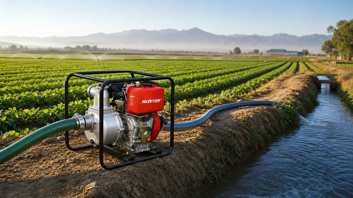
Many buyers focus only on horsepower or pump size when selecting a water pump. However, pump performance depends on several factors, including flow rate, head lift, water type, operating time, and power source. A pump that works well for irrigation may not be suitable for drainage or construction applications.
This guide explains how to choose the right water pump based on different applications and helps you understand the key specifications before making a purchase.
What Is a Water Pump and How Does It Work?
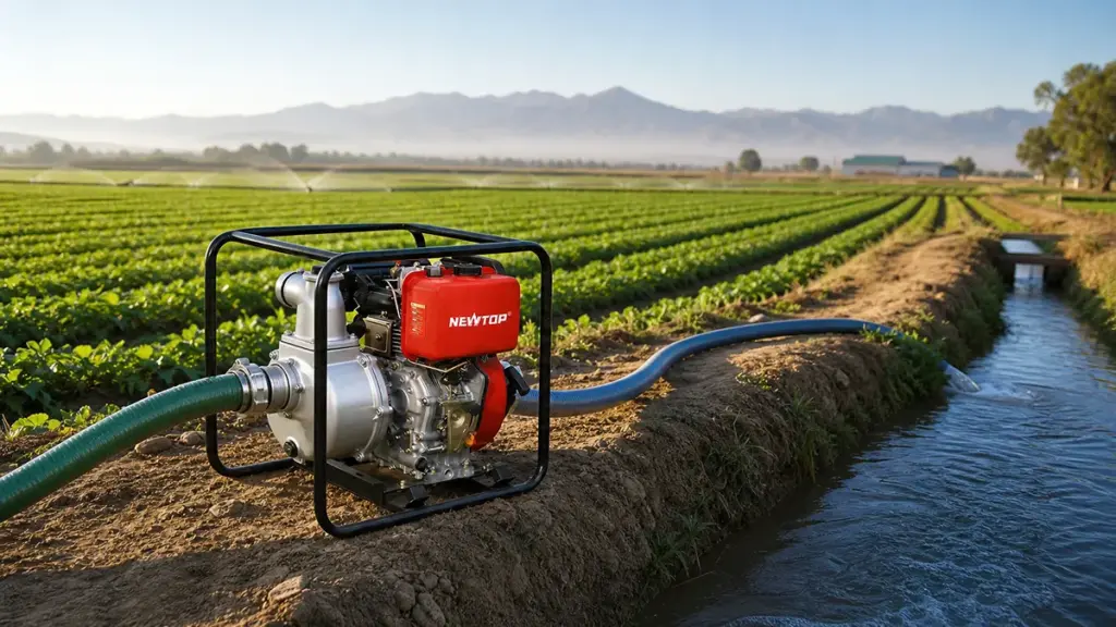
A water pump converts mechanical energy into hydraulic force to move fluid, overcome friction, and deliver the necessary flow and pressure for irrigation, drainage, and construction sites.
A water pump is a mechanical device designed to move water from one location to another by converting engine or motor power into water pressure and flow. Portable water pumps usually use gasoline or diesel engines to drive an impeller, which creates centrifugal force and pushes water through the discharge outlet.
Most portable pumps work based on centrifugal pump technology. When the engine starts, the impeller rotates at high speed and creates a low-pressure area at the pump inlet. Water is drawn into the pump chamber, accelerated by the impeller, and pushed out through the discharge pipe.
The basic working process includes:
- The engine provides power to rotate the impeller.
- The impeller creates suction and moves water into the pump body.
- The pump casing converts kinetic energy into pressure.
- Water is discharged through the outlet pipe.
Related reading: Portable Water Pumps: A Practical Guide for Different Applications
Key Water Pump Specifications to Compare
| Specification | What It Means | Why It Matters |
|---|---|---|
| Flow Rate | The amount of water a pump can move within a specific time, usually measured in L/min, m³/h, or GPM. | Determines how quickly water can be supplied, transferred, or removed. |
| Total Head | The total height a pump needs to overcome, including vertical lift, pipe friction loss, and required outlet pressure. | Shows whether the pump can deliver water to the required distance and elevation. |
| Engine Power | The output power of the engine, usually measured in horsepower (HP) or kilowatts (kW). | Affects pumping capacity, pressure performance, and ability to handle demanding applications. |
| Suction Height | The vertical distance between the water source and the pump inlet. | Determines how effectively the pump can draw water from wells, tanks, ponds, or other sources. |
| Water Type | The condition of the water, such as clean water, muddy water, or water containing solid particles. | Helps determine whether you need a clean water pump, trash pump, or another specialized pump type. |
For a more detailed breakdown, you can also read our beginner’s guide to water pump specifications, which explains these parameters in depth.
Maximize Profit with Durable OEM Machinery
What Are the Main Types of Water Pumps?
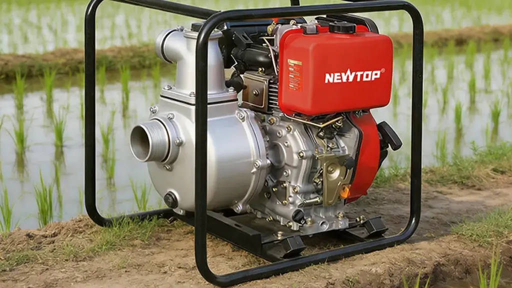
Water pumps can be classified according to their structure, power source, and application. For portable outdoor equipment, the most common types are clean water pumps, trash pumps, and high-pressure pumps.
If you want to better understand how different pump designs affect performance and priming ability, it’s also helpful to compare centrifugal and self-priming water pumps, or trash water pump vs clean water pumps, which we explain in detail in our guide on pump working principles and selection differences.
Centrifugal Pumps
Centrifugal pumps rely on a rotating impeller to add velocity to water and convert that velocity into usable pressure. They consistently deliver high efficiency for systems demanding moderate-to-high flow rates.
- Primary Applications: The standard choice for surface-water irrigation and general water transfer.
- Maintenance Factor: Requires manual priming in most standard surface installations.
- Liquid Constraint: Struggles to process heavily solids-laden or muddy water.
Submersible Pumps
Installed entirely below the water line, these units push water upward rather than pulling it. This submerged design entirely eliminates suction lift limitations and bypasses the need for manual priming.
- Core Environments: Commonly deployed in deep wells, drainage pits, and flooded basements.
- Operational Advantage: Works directly in the fluid to solve complex or deep suction-lift problems.
- Selection Requirement: Demands specific matching to depth and water quality to prevent submerged maintenance difficulties.
Jet Pumps
A jet pump utilizes an ejector mechanism to create strong suction and pull water directly from the source. Operators primarily install these units above ground to keep the hardware accessible for routine maintenance.
- Best Fits: Highly effective for shallow wells and specific above-ground irrigation supply setups.
- Suction Limits: Faces strict suction-lift restrictions compared to submerged pump alternatives.
- Efficiency Profile: Operates at lower overall efficiencies than standard centrifugal models.
Diaphragm and Positive-Displacement Pumps
This pump category displaces a fixed volume of liquid per cycle using a flexible mechanical mechanism. The physical design delivers strong self-priming capabilities tailored for demanding suction environments where standard pumps lose prime.
- Liquid Tolerance: Handles highly viscous, dirty, or chemically contaminated liquids effectively.
- Flow Characteristics: Produces lower maximum flow rates compared to centrifugal alternatives.
- Discharge Style: Often creates a pulsating discharge rather than a steady, continuous stream.
Trash and Booster Pumps
Neither of these units serves as a general-purpose lifting solution. They exist specifically to address strict environmental conditions or solve system performance constraints that standard equipment cannot handle.
- Trash Pumps: Feature large internal passages engineered to pass solids, sediment, and mud safely during heavy construction dewatering.
- Booster Pumps: Focus entirely on increasing pressure within an existing pressurized line or an underperforming irrigation zone.
How to Choose a Water Pump for Irrigation

Choosing an irrigation pump comes down to matching your required flow rate and total dynamic head to your water source depth while operating near peak efficiency.
Assessing Your Water Source and Quality
The origin of your water dictates the physical hardware you need to install. If you draw from a deep well, physical suction limits render surface pumps useless, forcing you to rely on a submersible model. Conversely, shallow ponds, storage tanks, or canals pair perfectly with standard centrifugal or self-priming surface setups.
Water quality also dictates pump survival. If your source frequently pulls in sand, silt, or agricultural debris, a standard clear-water pump will suffer severe abrasion and rapidly lose pressure. Dealing with debris-laden water requires targeted inline filtration or a drainage-style pump built with larger clearances to prevent clogging.
Calculating Flow Rate and Total Dynamic Head (TDH)
Pump selection relies heavily on calculating two precise performance metrics for your specific site.
- Flow Rate (GPM or LPM): Size your capacity based on the peak simultaneous demand or the single largest irrigation zone in your layout.
- Total Dynamic Head (TDH): Calculate this by adding the vertical suction lift, static elevation change, pipe friction loss, and your required outlet pressure.
- System Distribution Type: Factor in the delivery method, as high-impact sprinkler systems demand much higher continuous pressure than low-flow drip irrigation setups.
Selecting the Appropriate Pump Type
Once you map your head and flow numbers, match the pump style directly to your environmental conditions.
- Centrifugal Surface Pumps: The standard choice for highly efficient operation when transferring clean water from shallow sources at moderate head.
- Submersible Pumps: These sit directly below the water line, entirely bypassing suction lift limitations and eliminating surface priming issues.
- Self-Priming External Pumps: Ideal for above-ground surface transfer where operators need the practical convenience of quick suction recovery.
Matching Power Source and Efficiency Requirements
Buying a pump purely based on horsepower is a common sizing error. A massive motor operating far outside its intended duty point wastes electrical or fuel energy and increases mechanical wear. You must check the manufacturer’s performance curve to ensure your calculated flow and TDH intersect near the Best Efficiency Point (BEP).
Always verify that your site’s power capabilities match the exact motor requirements. Whether you rely on single-phase electric, three-phase power, or a portable diesel engine, the energy supply must handle the startup draw and continuous duty cycle to keep your irrigation system running reliably.
How to Choose a Water Pump for Drainage and Dewatering
Selecting the right drainage or dewatering pump requires matching flow rate, total dynamic head, and solid-handling capabilities to your exact site conditions and power constraints.
Assess the Water Source and Quality
Pump selection begins with a precise evaluation of the job site. You must define the task as either drainage for nuisance water removal or dewatering for continuous site drying. The location of the water source dictates the fundamental pump configuration, while the water composition determines the internal mechanics required to prevent premature failure.
- Task definition: Distinguish between temporary drainage and continuous active dewatering.
- Source location: Identify the water depth to determine whether an above-water or submersible setup minimizes suction losses.
- Water quality: Evaluate the water for sand, silt, or debris to ensure the chosen model handles expected solids without excessive wear or clogging.
Calculate Flow Rate and Total Dynamic Head (TDH)
Sizing a pump relies on hard calculations, not horsepower estimates. Determine the required flow rate in cubic meters per hour, and add a safety margin to account for sudden rainfall or unexpected groundwater seepage. Next, you must calculate the Total Dynamic Head (TDH) to understand the true pressure demand on the system.
- Static lift: The exact vertical distance the water must travel from source to discharge.
- Friction losses: The resistance caused by water moving through pipes, fittings, and valves.
- Discharge pressure: The specific pressure required at the outlet point.
Factor in long discharge distances carefully. Extended hoses and elevation changes significantly impact total system demand and can render an improperly sized pump useless on site.
Select the Appropriate Pump Type
The pump architecture must match both the physical environment and the water composition. Using a clean-water pump for a muddy excavation guarantees rapid mechanical failure.
- Submersible drainage pumps: Use these for flooded sumps and ponds to completely eliminate suction lift limitations.
- Trash or solids-handling pumps: Select these for construction pits containing muddy or abrasive silt-laden water.
- Dedicated dewatering pumps: Choose these heavy-duty units for continuous trench and foundation work that requires handling high flow volumes.
Verify the Pump Curve and Power Supply
Never buy a pump based solely on its maximum theoretical output. You must match your operating duty point to the middle of the manufacturer’s pump curve, known as the Best Efficiency Point (BEP). Operating near the BEP maximizes electrical efficiency and prevents severe mechanical wear.
- Power compatibility: Confirm the site offers compatible power, whether single-phase electric, three-phase electric, petrol, or diesel.
- Duty cycle matching: Select a motor rated for the anticipated daily duty cycle.
- Continuous operation: Verify the unit supports continuous running during heavy storms or prolonged excavation work.
Evaluate Installation Constraints and Maintenance Needs
Physical site limitations often dictate the final model selection. Verify the physical pump dimensions to guarantee the unit fits narrow boreholes, small sumps, or confined excavations. A tight fit can restrict intake flow and cause overheating.
- Piping constraints: Secure all piping connections to prevent casing strain under heavy load.
- Intake protection: Consistently use recommended strainers to block large debris from destroying the impeller.
- Serviceability: Prioritize models with accessible maintenance features and strong service support for critical continuous applications.
How to Choose a Water Pump for Construction Sites
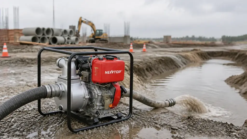
Select a construction water pump based on flow, total head, and solids tolerance before looking at horsepower to avoid downtime and excessive wear.
Calculate Required Flow Rate and Total Head
Determine the volume of water you need to move per minute or hour to keep excavation areas clear and usable. This establishes your target flow rate. Next, calculate the total dynamic head (TDH). This calculation requires three specific inputs:
- Vertical lift: The physical distance from the water surface to the discharge point.
- Friction losses: The resistance created by hoses, pipes, and fittings along the run.
- Discharge pressure: The specific force required at the final outlet.
Compare these precise requirements against the actual operating pump curve. Relying solely on nominal horsepower ratings often leads to undersized or inefficient equipment.
Assess Water Quality and Solids Content
Construction sites rarely deal with clean water. Identify whether the site requires pumping clean water, muddy water, sand-laden fluid, or water heavy with debris. Match the actual water conditions with appropriate impeller types and clog-resistant designs found in trash or solids-handling pumps. You must account for suspended solids early in the selection process to prevent premature wear, sudden clogging, and unexpected downtime on the job site.
Determine Suction Depth and Pump Configuration
Measure the exact distance from the water surface to your intended pump intake. You can utilize surface or self-priming pumps for shallower applications where the suction lift remains within practical limits. Switch to submersible pumps if the source depth exceeds 7 to 8 meters. At that depth, surface suction becomes ineffective and will cause performance failures.
Evaluate Power Availability and Portability Needs
Check the site for a reliable single-phase or three-phase electrical supply to support electric pumps. Select diesel-driven or combustion pumps for remote sites, emergency flood control, or areas lacking stable infrastructure. Consider the physical footprint and mobility required to move the unit between different dewatering zones as the project scales.
Factor in Duty Cycle and Operating Margins
Include a 10 to 20 percent safety margin in your capacity calculations to handle real-world variations, seasonal level changes, and minor obstructions. Prioritize automatic controls like float switches or level sensors for repeated or continuous drainage tasks to reduce manual oversight. Verify you have adequate Net Positive Suction Head (NPSH) margins to avoid cavitation, especially when using long suction lines or operating in shallow water.
How to Choose Between a Gasoline and Diesel Water Pump
Select gasoline pumps for quick deployment and intermittent use, but switch to diesel when operations demand heavy-duty autonomy, long daily hours, and lower lifetime fuel costs.
| Comparison | Gasoline Water Pump | Diesel Water Pump |
|---|---|---|
| Power Output | Suitable for light and medium-duty applications that require flexible and portable pumping solutions. | Provides stronger performance for heavy-duty applications and long-duration pumping operations. |
| Fuel Efficiency | Generally has higher fuel consumption during continuous operation. | Usually offers better fuel efficiency when running for extended working hours. |
| Weight | Lighter design makes it easier to transport and move between different job locations. | Typically heavier because of the stronger diesel engine structure and components. |
| Maintenance | Simple maintenance requirements and easier starting performance. | Built for durability and demanding working environments with longer service needs. |
| Best Applications | Small farms, gardens, water transfer, and emergency drainage tasks. | Construction sites, industrial drainage, mining, and large-scale irrigation projects. |
When to Choose a Gasoline Water Pump
Gasoline engines excel in scenarios that prioritize speed and ease of movement over continuous operation. These units weigh significantly less, making them easy to carry across temporary setups, tight enclosures, or rough terrain by a single operator.
They feature simple startup procedures tailored for occasional, non-intensive use. This makes them highly effective for sporadic tasks, emergency water transfer, or rapid flood response. A gasoline pump fits perfectly into moderate flow requirements where the immediate convenience of deployment outweighs the need for long-term fuel efficiency.
When to Choose a Diesel Water Pump
Diesel engines are built for endurance. You select a diesel pump when the job involves prolonged daily workloads or continuous heavy-duty operation. Manufacturers design these units with robust structural frames capable of withstanding harsh, demanding environments for extended periods without degradation.
While they carry a higher upfront cost and a heavier footprint, diesel pumps deliver superior fuel efficiency over time. This translates to a notably lower total cost of operation for high-hour usage. They become the default choice when equipment autonomy, durability, and raw pumping power outrank lightweight portability.
How to Match Pump Size, Flow Rate, and Head to Your Application
Matching the right pump means balancing flow rate and total dynamic head against your specific water source. Oversize it, and you waste energy; undersize it, and your system starves.
| Application | Primary Focus | Key Sizing Factor |
|---|---|---|
| Irrigation | Precise flow and pressure | Simultaneous zone flow + TDH |
| Drainage | Fast evacuation | Total volume + solids handling |
| Construction | Mobility & dirty water | Peak inflow + high TDH |
Understanding Core Sizing Variables
You cannot select a pump based on horsepower alone. A successful installation requires matching the physical properties of the water source to the mechanical output of the equipment. Buyers must define four specific variables before reviewing product catalogs.
- Flow rate (Q): The volume of water moved per unit of time, typically measured in L/min, m³/h, or GPM.
- Total Dynamic Head (TDH): The total resistance the pump must overcome, combining vertical lift and friction.
- Source depth: A depth exceeding 7-8 meters generally requires switching from a surface pump to a submersible model.
- Water type: The presence of solids, sludge, or debris dictates pump material and design compatibility.
Calculating the Required Flow Rate
Flow rate defines how much water moves through your system at any given moment. Sizing this metric correctly prevents both equipment strain and wasted operating expenses.
- Irrigation applications: Require summing the flow of all emitters or zones operating simultaneously.
- Dewatering and construction: Require calculating the total volume of accumulated water against the target evacuation time.
- Cost factors: Oversizing the flow rate unnecessarily increases initial equipment costs and energy consumption.
Determining Total Dynamic Head (TDH)
TDH represents the actual physical resistance the pump pushes against. If you miscalculate this variable, your pump will fail to deliver water at the final destination.
- Static head: The physical vertical distance between the water level and the final discharge point.
- Friction losses: Pressure drops caused by water traveling through pipes, elbows, valves, and filters.
- Required operating pressure: The minimum pressure needed at the final delivery point to operate sprinklers or other equipment.
Reading the Pump Curve and Adding Safety Margins
Every pump has a performance curve showing exactly how flow drops as head increases. Operators run into trouble when they force a pump to work outside its intended functional range.
- Target the middle: Select a pump where the calculated flow and head intersect near the middle of its efficiency curve.
- Build in a buffer: Incorporate a 10-20% safety margin to account for system wear, seasonal water level drops, and real-world variations.
- Prevent wear: Avoid selecting pumps that operate at the extreme limits of their performance curves to prevent premature failure.
Application-Specific Selection Criteria
A pump built for one job often fails in another. Different industries prioritize completely different mechanical parameters.
- Irrigation systems: Prioritize precise flow per zone, TDH, and hydraulic efficiency.
- Drainage setups: Focus on rapid evacuation capacity, solids handling, and continuous operation reliability.
- Construction dewatering: Demands robust resistance to dirty water, high mobility, and flexible installation.
Match the pump specifications strictly to the physical environment, and the equipment will deliver the required performance without unnecessary downtime.
Common Water Pump Selection Mistakes to Avoid
Most pump failures stem from sizing by horsepower rather than matching flow and total dynamic head to site-specific conditions, causing inefficient operation and premature wear.
Sizing and Performance Miscalculations
The fastest way to ruin a pumping system is choosing equipment based on horsepower alone. Motor size is a result of system requirements, not the starting point. Buyers consistently run into trouble when they fail to match the system demand for flow rate and Total Dynamic Head (TDH).
Calculating TDH accurately requires accounting for static lift, friction losses through pipes and fittings, and the required outlet pressure. Omitting any of these variables results in underperforming systems. Another frequent error is sizing based on a daily average rather than the peak simultaneous operating demand, leaving critical zones starved for water during heavy use.
When flow and pressure capabilities mismatch the specific operating point of the delivery system, the pump operates too far from its Best Efficiency Point (BEP). Forcing a pump to run on the extreme left or right of its performance curve drastically increases mechanical wear and destroys efficiency.
Overlooking Water Quality and Site Conditions
Matching the physical pump to the actual site environment is just as critical as hitting the right performance curve. Operators frequently try to use standard clean-water pumps for drainage or construction dewatering. When the water contains sediment, debris, or abrasives, these standard impellers quickly clog or wear out.
- Suction Limits: Ignoring suction lift conditions and failing to ensure available NPSH exceeds required NPSH leads directly to cavitation.
- Power Mismatches: Skipping basic power supply checks results in voltage, phase, or frequency conflicts that prevent the system from running.
- Fluid Chemistry: Disregarding abrasive particles or corrosive water chemistry causes premature casing and seal failures without specific corrosion-resistant materials.
Application-Specific Pitfalls
Every job site presents unique hydraulic challenges. Failing to adjust for the specific application guarantees poor performance.
- Irrigation: Buyers often fail to convert individual emitter needs into accurate total pump requirements or ignore the heavy friction losses that occur by the time water reaches the field edge.
- Drainage: Sizing flow capacity too low for unexpected stormwater peaks leaves areas flooded, while using the wrong impeller style guarantees persistent clogging.
- Construction: Site managers routinely underestimate the total head generated by long temporary discharge runs and sudden elevation changes across an active site.
Neglecting Duty Cycle, Installation, and Maintenance
Even perfectly sized equipment fails if the installation and operating habits are flawed. Underestimating total operating hours is a common trap. Selecting a pump rated only for intermittent use and forcing it into continuous duty cycles causes rapid motor burnout.
Physical installation errors compound these problems. Operating without proper priming mechanisms, missing strainer protection, or using unsecure mounting setups creates destructive vibration. Site operators also overlook the severe risks of dry-running or closed-valve operation, which can melt internal seals in minutes.
Ignoring physical site constraints ensures long-term maintenance headaches. Narrow boreholes, tight footprints, or difficult access points make routine servicing nearly impossible, turning minor preventative maintenance into a massive teardown project.
NEWTOP Water Pumps for Irrigation, Drainage, and Construction
As an outdoor power equipment manufacturer, NEWTOP develops portable water pumps designed for agriculture, construction, drainage, and general water transfer applications.
NEWTOP water pumps combine reliable engine performance with practical designs for different working environments. Whether customers need irrigation support, emergency water removal, or construction dewatering solutions, selecting the right pump model ensures better efficiency and longer service life.
Key advantages of NEWTOP water pumps include:
- Reliable engine performance: Designed for stable operation in outdoor working conditions.
- Multiple application options: Solutions available for clean water transfer, irrigation, and drainage applications.
- Durable construction: Strong pump bodies and frames improve product lifespan.
- Easy maintenance: Practical designs help reduce downtime during daily operation.
- OEM and bulk supply capability: Supporting distributors and international partners with customized solutions.
With years of experience in outdoor power equipment manufacturing, NEWTOP understands that different markets and applications require different pumping solutions. Whether you are sourcing for retail, industrial projects, or OEM branding, NEWTOP is ready to support you with reliable product quality, strong manufacturing capability, and flexible customization services. Contact us today to build a competitive and dependable water pump product line for your market.
Frequently Asked Questions
What size water pump do I need for irrigation?
Sizing an irrigation pump correctly requires determining the specific flow rate and total dynamic head (TDH). Calculate flow by adding the demand of the actual emitters or sectors running simultaneously, rather than the total theoretical field consumption. Next, calculate TDH by combining static lift, pipe friction losses, and the required emitter pressure. Select a pump whose performance curve places your target flow and TDH near its best efficiency point. Add a 10–20% safety margin to account for wear and seasonal variations. If your water source sits deeper than 7–8 meters, you need a submersible pump rather than a surface model.
How do I calculate total dynamic head for a water pump?
Total dynamic head (TDH) measures the total resistance your pump must overcome to move water. Calculate it by adding four specific components. First, measure the static head, which is the vertical distance from the water surface to the highest discharge point. Second, calculate friction losses caused by water moving through pipes, valves, and filters. Third, add the pressure head, which is the required operating pressure at the outlet like a sprinkler nozzle. Finally, include a 5–10% safety margin to accommodate seasonal water level drops and gradual component wear.
What is the difference between a clean water pump and a trash pump?
A clean water pump handles clear water with minimal suspended particles. Operators use these primarily for standard irrigation and general water transfer. A trash pump features larger impellers and volutes designed to pass mud, sand, leaves, and small solids without clogging. Construction crews rely on trash pumps for site dewatering, trench drainage, and flood control tasks where debris would instantly block or destroy a standard clean water pump.
How far can a portable water pump push water?
A pump’s effective reach depends entirely on its available pressure and total dynamic head, not horizontal distance alone. Pushing water over long horizontal runs creates friction, which directly subtracts from the pressure available at your discharge point. To find out if a portable pump can reach your target, calculate the total vertical lift and add the friction losses for your specific hose length and diameter. Check the pump’s performance curve to verify it can maintain the required flow at that total head.
How much horsepower do I need for a water pump?
Horsepower is a byproduct of your system requirements, not the starting metric for pump selection. The correct horsepower depends on your required flow rate, total dynamic head, and pump efficiency. Moving massive volumes of water or pushing it up steep inclines dictates a higher horsepower requirement. You should always select a pump by matching its performance curve to your target flow and head. Once you find that match, the manufacturer’s specifications dictate the necessary motor horsepower to maintain that duty point efficiently.
Can one water pump be used for irrigation and drainage?
Yes, a single pump handles both tasks if the flow rate, total head, and water quality align for both applications. A correctly sized centrifugal pump easily manages irrigation and clear-water drainage. But if your drainage task involves thick mud or construction debris, you must use a specialized trash pump. Trash pumps clear solids effectively but struggle to maintain the high, stable pressure required for agricultural sprinkler systems.
What happens if a water pump is too large for the job?
An oversized pump operates far from its best efficiency point, forcing you to pay for wasted energy and higher operating costs. In an irrigation setup, excess pressure damages fittings, blows out emitters, and creates uneven water distribution across the field. In drainage or construction applications, an oversized pump overwhelms temporary discharge lines or causes automatic float systems to short-cycle rapidly. This constant on-and-off cycling destroys bearings, degrades seals, and burns out the motor prematurely.

The NEWTOP Autumn Deals 2026 are here, bringing limited-time discounts and exclusive order rewards to qualified new customers.
From August 21 to September 30, 2026, earlier orders receive higher discounts. Qualified FOB orders can also unlock promotional gifts based on order value, giving distributors an additional reason to bring forward planned restocking, new product introductions, and mixed-category purchases.
Whether you are preparing for year-end sales, expanding your current range, or placing your first NEWTOP order, the promotion offers a practical opportunity to reduce procurement costs while building inventory around real market demand.

Autumn Discounts: The Earlier You Order, the More You Save
The highest discount is available during the opening stage. Buyers with confirmed requirements are encouraged to finalize their product specifications and quantities before August 31.
| Order Period | Discount |
|---|---|
| August 21–31, 2026 | 3% OFF |
| September 1–15, 2026 | 2% OFF |
| September 16–30, 2026 | 1% OFF |
The applicable discount will be based on the date the qualified order is confirmed within the promotion period.
Exclusive Gifts for Qualified Orders
In addition to the time-based discount, qualified orders can receive promotional gifts according to their FOB order value.
In addition to discounts, NEWTOP offers premium gift during the promotion period:
- Orders over $20,000
🎁 Huawei mobile phone, 100 branded T-shirts or hats - Orders over $10,000
🎁 High-quality Bluetooth speaker - Orders over $5,000
🎁 High-end backpack - Orders over $2,000
🎁 Bluetooth earphones
The above order amounts are for FOB value only.The promotional gifts are available only to the first 20 new customers.
Gift images are for reference only, and actual models, colors, and specifications are subject to the physical products supplied.
Make More of Your First NEWTOP Order
The Autumn Deals can support different purchasing plans, whether you are testing NEWTOP products for the first time, preparing stock for the next sales season, or adding related products to your existing range.
The promotion applies across NEWTOP’s main product categories, including outdoor power equipment, agricultural machinery, generators, water pumps, outboard motors, lithium battery tools, and replacement parts.
New customers can use the promotion to:
- Place an initial trial order for selected models
- Replenish products with clear local demand
- Combine complementary categories in one purchase
- Add common spare parts and accessories
- Begin an OEM or private-label project
A focused first order is often more practical than selecting too many unrelated products. Choosing several relevant models and the necessary service parts can make product evaluation, market testing, and future restocking easier.
Why Earlier Confirmation Matters
The opening stage provides the highest discount, but earlier confirmation can also make the order process more flexible.
Additional preparation time may be needed when an order includes:
- Multiple product models
- Market-specific technical configurations
- Custom colors, labels, or cartons
- Mixed machines and spare parts
- Special packaging or loading arrangements
Confirming these requirements early gives both sides more time to review the quotation, check product availability, prepare OEM materials, and arrange production and shipment.
To receive an accurate promotional offer, buyers should provide the main product models, quantities, destination market, technical requirements, and any customization needs. The NEWTOP sales team can then confirm the applicable discount, gift eligibility, and order details.
Secure Your Autumn Benefits Before September 30
The NEWTOP Autumn Deals 2026 run from August 21 to September 30 and are available exclusively to new customers.
Customers who place their orders earlier receive a higher discount, while qualified orders can also unlock promotional gifts according to their FOB value.
Please note:
- Promotional gifts are limited to the first 20 qualified customers
- Gift thresholds are calculated according to FOB order value
- The applicable discount depends on the order confirmation date
- Gift models and specifications are subject to actual availability
Contact the NEWTOP sales team with your product requirements to confirm availability, promotion eligibility, and the offer applicable to your order.
Order early, save more, and unlock extra rewards with your first NEWTOP purchase.
*NEWTOP reserves the right of final interpretation of this promotion.
Outboard motor propellers with the strongest repeat-sales potential in South America are generally three-blade aluminum replacement models for widely used small and mid-range outboards. For many distributors, the most practical starting points are the 9.9–15 HP and 25–40 HP engine families, followed by selected 40–60 HP applications.
This is not a continent-wide sales ranking. No public database tracks individual propeller SKU sales across every South American country. Brazil, Colombia, Chile, Peru, and other markets have different fleets, waterways, customer budgets, and recreational boating sectors.
A more reliable way to plan stock is to identify the engines already operating locally, then decide which propeller materials, pitches, and fitment specifications are most likely to generate repeat replacement demand.
A Practical South American Stocking Map
The following table is a distributor stocking model rather than published regional sales data.
| Inventory Position | Recommended Focus | Why It Deserves This Position |
|---|---|---|
| Deep Stock | Three-blade aluminum propellers for confirmed 9.9–15 HP engine families | Small fishing, inflatable, river, and utility boats create broad replacement demand |
| Core Stock | Three-blade aluminum propellers for established 25–40 HP engine families | Common commercial step-up for loaded fishing and transport boats |
| Selective Stock | Aluminum propellers for selected 40–60 HP engines, plus proven stainless-steel sizes | Useful where larger workboats or recreational fleets are already established |
| Order-Backed Range | Four-blade, premium stainless-steel, uncommon pitch, rotation, or hub configurations | Demand is more application-specific and easier to supply against confirmed orders |
The important phrase is confirmed engine families. Stocking a wide horsepower range is not useful when the propeller hubs, spline counts, diameters, or pitches do not match the engines customers actually operate.
Signal One: Which Outboards Are Already Working Locally?
Propeller turnover follows the installed engine population.
Recent public-sector purchasing in Brazil includes 15 HP two-stroke outboards paired with six-metre aluminum boats designed for up to 25 HP. In Colombia, the national fisheries authority reported the delivery of fiberglass fishing boats fitted with 40 HP outboards in 2025. An FAO description of Chilean small-scale benthic fisheries also records open boats using outboards from approximately 10 to 45 HP. These sources are not retail propeller sales reports, but they illustrate why the small and mid-range engine bands remain commercially important.
For a distributor, this means the first inventory decision should not be:
Which propeller sizes are popular worldwide?
It should be:
Which outboard models appear most often in our engine sales, workshop repairs, customer inquiries, and local fishing fleets?
A dealer already selling 15 HP, 30 HP, and 40 HP outboards has a natural starting point. Propeller stock should first support those engines before expanding into unrelated models.
Useful local evidence may come from:
- Outboard sales records
- Workshop service history
- Damaged-propeller replacements
- Customer photographs and part inquiries
- Government boat projects
- Fishing and transport associations
- Competitor engine availability
This produces a better SKU list than selecting propellers only from a general catalog.
Signal Two: What Work Does the Boat Perform?
Two boats using the same horsepower may create different propeller demand.
A lightly loaded inflatable may prioritize easy planing and general-purpose performance. A fishing boat carrying nets, fuel, ice, crew, and catch places greater emphasis on acceleration and load handling. River transport boats may operate with changing passenger or cargo weights, while recreational users may pay more attention to cruising speed.
The boat’s normal work influences which pitch variations should be available.
Small Fishing and Utility Boats
For portable and light commercial engines, replacement buyers often prioritize:
- Affordable price
- Direct fitment
- Ready availability
- Reliable general performance
- Easy replacement after impact damage
This supports deeper inventory of standard three-blade aluminum models.
Loaded Commercial Boats
A working boat that regularly carries cargo or fishing equipment may need a different pitch from a lightly loaded boat using the same engine.
A dealer serving this market should consider carrying:
- The standard replacement specification
- One confirmed load-oriented alternative
- Matching washers, nuts, pins, and hub components
This gives the workshop a practical second option without creating too many slow-moving SKUs.
Recreational and Performance Boats
Some customers are willing to pay more for stainless steel, sharper acceleration, improved grip, or higher-speed performance.
These products can sell well in the right coastal, lake, or leisure-boating channel. However, they usually require more precise engine and boat matching, so they should not automatically receive the same inventory depth as standard aluminum replacements.
Signal Three: Material and Blade Count
Three-Blade Aluminum Is the Safest Core Range
Aluminum three-blade propellers offer a useful balance of cost, weight, availability, and broad application coverage.
Yamaha describes its general aluminum three-blade propellers as lightweight, low-cost products providing good overall performance across a wide outboard range. Mercury similarly positions aluminum propellers around value and versatility.
These characteristics suit many South American replacement channels because:
- Working boats need affordable downtime solutions.
- Propellers may encounter shallow water, rocks, timber, sand, or fishing gear.
- Customers often want to restore normal operation rather than purchase a performance upgrade.
- Distributors can cover more engine families with the same inventory budget.
This does not mean every aluminum propeller will sell. Compatibility and pitch still determine whether a particular SKU moves.
Stainless Steel Should Follow Proven Demand
Stainless steel can provide thinner, more rigid blades and greater resistance to flex. It is commonly positioned as a more durable and performance-oriented material than aluminum.
A selective stainless-steel range can make sense for:
- Higher-horsepower outboards
- Recreational fishing boats
- Offshore applications
- Customers replacing an existing stainless propeller
- Engine families with repeat premium-part demand
For a new distributor range, confirmed demand is safer than carrying many stainless sizes in advance.
Four-Blade Propellers Solve Specific Problems
Four-blade propellers may improve acceleration, grip, handling, or load performance in particular installations. Mercury and Yamaha both offer four-blade products for applications where stronger acceleration or load-carrying performance is required.
They are better treated as a solution to a known operating issue, such as:
- Slow planing under load
- Poor acceleration
- Ventilation during turns
- Heavy or changing payloads
- Greater low-speed control requirements
Without confirmed local applications, four-blade inventory can become fragmented across too many pitches and engine families.
Signal Four: Pitch Creates More SKUs Than Horsepower
One of the biggest stocking mistakes is assuming that every 15 HP or 30 HP outboard uses one standard propeller.
Official propeller catalogs demonstrate otherwise. Suzuki’s parts catalog, for example, lists several three-blade aluminum pitch options for the same 9.9–20 HP engine groups and another broad range for 25–30 HP applications.
Pitch affects engine speed and boat behaviour. Adding pitch generally reduces wide-open-throttle engine RPM, while reducing pitch raises RPM and may improve acceleration. Too much pitch can overload the engine; too little can allow excessive RPM.
The correct stocking decision therefore depends on:
- Boat weight
- Normal passenger or cargo load
- Hull design
- Engine gear ratio
- Operating altitude
- Desired acceleration
- Recommended engine RPM range
For a common engine family, carrying one standard pitch and one locally proven alternative is often more useful than stocking one pitch across several unrelated horsepower classes.
Horsepower Is Not a Fitment Specification
A product labeled “for 40 HP outboards” does not contain enough information for an accurate order.
Engines with the same horsepower may use different:
- Propeller-shaft splines
- Gearcase dimensions
- Hub systems
- Gear ratios
- Propeller diameters
- Rotation directions
- Thrust washers
- Propeller nuts
- Spacer arrangements
Diameter and pitch markings are only part of the identification.
A distributor should organize each SKU around:
- Compatible outboard model or engine family
- Diameter and pitch
- Number of blades
- Material
- Spline count
- Hub or rubber-bush design
- Right- or left-hand rotation
- Required mounting hardware
- Cross-reference number, where available
This information should appear in the catalog, warehouse label, quotation, and sales record.
A clear fitment system reduces returns more effectively than simply carrying a larger number of propellers.
Where the Inventory Mix Changes
South America should not be treated as one uniform marine market.
A river-focused distributor may see stronger demand for affordable aluminum props, load-oriented pitches, and 15–40 HP applications. A dealer serving recreational coastal boats may need a narrower but more premium stainless-steel range. Workshops near fishing communities may prioritize immediate replacement availability, while importers serving multiple countries may benefit from mixed orders organized around several established engine families.
The following market patterns can guide the final range:
Fishing and River Transport Markets
Prioritize:
- Aluminum three-blade replacements
- Common 9.9–15 HP and 25–40 HP families
- Standard and load-oriented pitch options
- Mounting hardware and hub components
- Easily reordered repair parts
Mixed Commercial and Recreational Markets
Add:
- Selected 40–60 HP applications
- Several proven stainless-steel models
- More than one performance target per engine family
- Better product identification and application guidance
Emerging or Uncertain Markets
Start with:
- Engines already sold by the distributor
- Workshop-requested replacement parts
- Small mixed quantities
- Customer-specific special pitches supplied against orders
The opening range should become deeper only after actual sell-through data identifies the strongest SKUs.
Building the Range Around NEWTOP Outboards
The current NEWTOP outboard motor collection includes 9.9 HP, 15 HP, 18 HP, 30 HP, and several 40 HP models. The T15-63V is listed with a 9-1/4 × 9 propeller, while the T40G and T40J offer 12- and 13-inch propeller options. This product ladder gives distributors a practical foundation for small fishing, transport, utility, and leisure applications.
NEWTOP’s replacement propeller page describes propellers produced with controlled blade geometry, thickness consistency, curvature shaping, and surface finishing. The stated design goals include stable rotation, efficient power transfer, smoother acceleration, and load-handling performance.
For an accurate NEWTOP propeller quotation, buyers should provide:
- Outboard model
- Existing propeller markings
- Diameter and pitch
- Spline count
- Boat type
- Normal operating load
- Required quantity
- A clear photograph of the existing propeller, where possible
The recommended internal links in this section are:
These should link to the two official NEWTOP pages provided for this article.
A Smarter First Order
A first propeller order does not need to cover every boat and every engine in the region.
A more controlled assortment is:
Keep deeper stock
- Confirmed 9.9–15 HP engine families
- Confirmed 25–40 HP engine families
- Three-blade aluminum construction
- Standard replacement pitches
- Frequently required mounting components
Keep limited stock
- Selected 40–60 HP aluminum propellers
- One proven alternative pitch for heavy-load applications
- Stainless steel for engine families with known demand
Supply against confirmed orders
- Four-blade models
- Uncommon spline or hub systems
- Left-hand rotation
- Premium performance props
- Special diameter and pitch combinations
After the first sales cycle, reorder decisions should be based on sell-through speed, workshop requests, return reasons, engine models serviced, and local load conditions.
Which Outboard Propellers Are Most Likely to Keep Selling?
The strongest general-purpose outboard motor propellers for many South American distributors are three-blade aluminum replacements for established small and mid-range engine families.
The most defensible opening strategy is to:
- Build deep coverage around locally common 9.9–15 HP engines.
- Add the 25–40 HP models used in fishing, transport, and utility work.
- Carry selected 40–60 HP aluminum propellers.
- Add stainless steel and four-blade designs only where local demand supports them.
- Identify every SKU by complete engine and propeller fitment—not horsepower alone.
The best-selling range will ultimately be determined by the engines already in the market. A compact assortment built around real service demand will usually turn faster than a much larger catalog assembled from horsepower labels alone.
Gasoline generator price is not a single fixed number for every distributor. The same output class can receive different quotations depending on the engine and alternator, starting system, electrical configuration, order quantity, branding, packaging, destination, and trade term.
Prices shown on NEWTOP’s Alibaba.com storefront can help buyers make an initial budget estimate. However, they should be treated as reference information rather than a standing offer for every order. A confirmed quotation must be based on the required quantity, specification, customization, destination, and delivery scope.
The practical question is therefore not only, “How much does the generator cost?” It is also, “What exactly is included in that price?”
A Generator Quotation Is a Defined Scope
Two offers can carry the same output description while covering different products and commercial responsibilities.
One quotation may cover a recoil-start generator in neutral packaging, collected from the factory. Another may include electric start, a battery, wheels, market-specific sockets, branded cartons, spare parts, and delivery to an export port.
Their unit prices should not be compared until the technical specifications and commercial terms are aligned.
| Cost Layer | What Can Change | What the Buyer Should Confirm |
|---|---|---|
| Base Generator | Output, engine, alternator, frame, and protection | Are the machines technically equivalent? |
| Market Configuration | Voltage, frequency, phase, sockets, and documents | Is the generator suitable for the destination? |
| Order Setup | Quantity, model mix, branding, and packaging | Which costs are included in the unit price? |
| Logistics | Trade term, carton size, freight, and local charges | What remains payable after the factory quotation? |
| After-Sales Preparation | Spare parts, warranty, and service support | Has the cost of supporting the product been considered? |
Each layer can change the final unit cost even when the product photographs look similar.
The Base Generator Sets the Starting Price
The main product cost comes from the machine itself. Output class, engine displacement, alternator design, control system, fuel tank, frame, and included accessories all influence the factory quotation.
NEWTOP’s current generator collection lists gasoline models across several output classes, including 2.8 kW, 5.5 kW, 7.8 kW, and 10 kW units. Moving between these classes can involve changes in the engine, alternator, frame, overall weight, fuel demand, and transport requirements.
Rated Output Must Be Compared with Rated Output
A product title may highlight maximum output because it is the larger number. Distributors should use rated output when comparing normal operating capacity.
Two products promoted as “5 kW generators” may not provide the same continuous output. The quotation should therefore show rated and maximum power separately, together with the required voltage, frequency, and phase.
Comparing only the leading number in a product title can result in quotations for different machine classes.
Engine and Alternator Specifications Matter Together
A larger engine can support greater mechanical demand, but engine displacement alone does not define the electrical performance of the finished generator.
Alternator capacity, winding material, voltage regulation, cooling, and component matching also affect the configuration and price.
Buyers should request enough technical detail to identify what is being supplied rather than relying on broad descriptions such as “copper generator” or “high-power engine.”
Starting, Control, and Mobility Options Add Cost
Electric start normally requires more components than recoil start. Depending on the model, the system may include a starter motor, switch, charging circuit, battery holder, wiring, and battery.
The quotation should state clearly whether the battery is included. A battery shown in a product photograph does not necessarily confirm that it is included in the export package.
Control-panel choices can also change the price. These may include:
- Socket type and quantity
- Breakers and meters
- Voltage selectors
- DC output
- ATS connections
- Single-phase or three-phase layouts
Wheels, folding handles, reinforced frames, plugs, tools, and protective covers may appear to be small additions. Several options combined, however, can create a noticeable difference in both product and packaging cost.
Destination Requirements Can Change the Same Base Model
A generator suitable for one market may need a different electrical and documentation package for another.
The destination can determine:
- 50 Hz or 60 Hz frequency
- 110–127 V or 220–240 V output
- Single-phase or three-phase configuration
- Local socket and plug types
- Warning labels and manual language
- Required certifications or test documents
Some changes use standard components. Others may require a different alternator winding, control panel, labeling process, inspection scope, or minimum production quantity.
A reference price based on one configuration should not be applied automatically to another country. The destination market must be confirmed before the supplier can calculate an accurate quotation.
The Order Structure Changes the Unit Price
Once the technical specification is fixed, quantity and order design begin to influence cost.
Quantity Discounts Are Not Always Linear
Larger orders can spread production setup, printing, inspection, documentation, and internal handling across more units. However, doubling the quantity does not always produce a proportional price reduction.
A more meaningful saving may appear only when an order reaches a more efficient threshold for:
- Component purchasing
- Production scheduling
- Packaging
- Container loading
Buyers should request prices for realistic order quantities rather than asking for an extremely large-volume price that does not match the actual purchasing plan.
Mixed Models Trade Unit Cost for Inventory Flexibility
A distributor may prefer to combine several output classes in one container. This reduces dependence on a single model and makes it easier to test demand across different customer groups.
The trade-off is that each model may be produced in a smaller quantity. Custom cartons, labels, and production setup may also have separate minimums.
A mixed shipment can therefore carry a slightly higher average unit price while reducing inventory concentration and improving product-range flexibility.
OEM Scope Must Be Defined Clearly
Private labeling can mean a simple logo sticker or a complete brand program.
Possible requirements include:
- Custom machine colors
- Product and engine labels
- Control-panel graphics
- Printed cartons
- Branded manuals
- Barcodes and serial labels
- Warranty cards
- Market-specific warning stickers
These items do not all follow the same pricing method. Some are recurring unit expenses, while others involve one-time design, printing, or setup charges.
The quotation should separate those costs instead of presenting one unexplained “OEM fee.”
Sample Price Is Not the Bulk Price
A sample is produced and handled outside the efficiency of a normal bulk production run.
Its price may reflect:
- Small-quantity component purchasing
- Individual packaging
- Additional handling
- Higher freight per unit
- Sample inspection or preparation
The sample should be used to evaluate the product rather than predict the final bulk unit price.
After the configuration is approved, the supplier should issue a new quotation based on the intended production quantity and commercial requirements.
Packaging and Trade Terms Affect the Real Cost
Generator packaging has a direct relationship with logistics.
Carton dimensions, wheel placement, pallet use, internal protection, and stackability influence how many generators fit into a container and how well they survive transportation.
A small factory-price saving may become meaningless when oversized packaging reduces the container quantity. At the same time, removing too much protection can increase transit damage and warranty claims.
Trade terms must also be compared on the same basis. EXW, FOB, and CIF allocate different costs, risks, and obligations between the buyer and seller. The agreed rule should be stated together with the exact named factory, port, or destination.
A lower EXW quotation may become more expensive after factory collection, export handling, freight, and local charges are added. A quotation that includes international freight may still leave customs clearance, duties, destination handling, and warehouse delivery to the buyer.
The unit price has little commercial meaning until the buyer understands where the supplier’s responsibility ends.
Convert the Quotation into Landed Cost
The distributor’s calculation should continue beyond the supplier’s unit price.
A practical formula is:
Landed cost per unit = quoted unit price + unit customization cost + allocated shipment cost per saleable unit + duties and taxes per unit + after-sales reserve per unit
Shipment-level expenses may include:
- Origin handling
- International freight
- Insurance
- Customs clearance
- Port charges
- Inspection
- Inland delivery
These expenses should be divided by the number of saleable generators in the shipment. Costs already included under the selected trade term must not be added twice.
The after-sales reserve may cover common spare parts, warranty replacements, technical materials, and service preparation.
This matters because the commercial cost of a generator continues after it reaches the distributor’s warehouse. A lower-priced machine can become more expensive when replacement parts are difficult to obtain, packaging damage is frequent, or local technicians cannot service the configuration efficiently.
Compare One Commercial Scope, Not Several Incomplete Prices
Before requesting a final quotation, prepare one order brief and send the same information to every supplier.
The brief should include:
- Rated and maximum output
- Engine and alternator requirements
- Voltage, frequency, phase, and sockets
- Recoil or electric starting
- Battery, wheels, and included accessories
- Quantity required for each model
- Destination country and port
- Branding and packaging scope
- Certification and document requirements
- Spare-parts package
- Preferred trade term
- Payment terms and delivery schedule
Also confirm the quotation currency, issue date, validity period, and whether the freight figure is fixed or indicative.
An unspecified feature should not be assumed to be included simply because it appears in a photograph. It should remain open until the supplier confirms it in the specification sheet or quotation.
Using one consistent order brief makes it possible to identify whether a price difference comes from the machine, the commercial scope, or the supplier’s actual cost level.
What the Final Gasoline Generator Price Should Tell You
Prices displayed online provide a useful starting point for product research and preliminary budgeting. The confirmed figure must still reflect the exact machine, quantity, destination-market configuration, customization, packaging, delivery scope, and after-sales requirements.
Once every quotation follows the same technical and commercial brief, distributors can compare landed cost instead of isolated unit prices. This makes it easier to protect resale margin, prepare service support, and avoid paying later for items missing from an incomplete offer.
The most useful quotation is not simply the lowest number. It is the one that clearly shows what the buyer will receive, what remains to be paid, and whether the complete order fits the target market.
