Blogues
Navegue em nossos blogs
- Todos
- Histórias de clientes NEWTOP
- Hub do Explorador NEWTOP
- NEWTOP Insights da indústria
Ao selecionar uma bomba de água para construção, agricultura, drenagem, ou aplicações industriais, escolher o tipo correto de bomba é fundamental. Duas das opções mais comuns são bombas de lixo e bombas de água limpa. Embora ambos sejam projetados para mover água, eles são construídos para condições de trabalho muito diferentes.
Uma bomba de água limpa é projetada para transferir água relativamente limpa com o mínimo de partículas, enquanto uma bomba de lixo é projetada para lidar com água lamacenta, águas residuais, e líquidos contendo detritos sólidos. Escolher a bomba errada pode levar à redução do desempenho, bloqueios frequentes, custos de manutenção mais elevados, ou até mesmo danos à bomba.
Neste guia, explicaremos a diferença entre bombas de água de lixo e bombas limpas bombas de água, incluindo seus princípios de funcionamento, capacidade de manipulação de líquidos, desempenho, aplicações, e como selecionar a solução certa para o seu mercado.
O que é uma bomba de lixo?

Uma bomba de lixo é um serviço pesado bomba centrífuga construído para mover agressivamente água suja carregada com lodo, areia, e detritos sem obstruir ou falhar.
Definição e propósito central
Engenheiros constroem bombas de lixo especificamente para movimentar água suja repleta de partículas sólidas, como lodo, areia, sujeira, e folhas. Isto contrasta diretamente com as bombas de água limpa padrão, que os operadores pretendem apenas para líquidos claros. If you expose a clean-water pump to heavy contamination, you risk immediate blockage or catastrophic seal failure. The industry categorizes trash pumps as dirty-water pumps because they operate effectively in demanding environments where liquids mix heavily with solid waste.
Key Design Characteristics
The ability to process solid waste requires a specific mechanical architecture. Manufacturers construct these pumps with reinforced components to survive constant internal abrasion.
- Large internal clearances: The design allows suspended solids and debris to pass straight through without plugging internal passages.
- Heavy-duty construction: Production relies on abrasion-resistant materials to withstand the mechanical impact and wear caused by sand and grit.
- Specialized impellers: Rotores abertos ou semiabertos e geometria de voluta especializada evitam matéria orgânica, fibras, ou plásticos se acumulem dentro da caixa.
Aplicações e ambientes típicos
Você implanta uma bomba de lixo quando o líquido que você precisa mover destruiria uma bomba de transferência padrão. Os operadores de campo contam com essas unidades em vários setores de serviços pesados.
- Controle de inundações: Desidratação de porões inundados, garagens, e áreas de trabalho enlameadas após condições climáticas severas ou rupturas de tubos.
- Construção e engenharia civil: Escavações de drenagem, trincheiras de serviços públicos, e bacias sedimentares cheias de águas subterrâneas e solo.
- Águas residuais e drenagem: Limpando esgotos, reservatórios, e canais de drenagem onde o acúmulo de resíduos orgânicos é comum.
- Gestão de resíduos industriais: Movendo efluentes do processo, pastas abrasivas, e fluxos com alto teor de sólidos dentro de estações de tratamento.
O que é uma bomba de água limpa?

Uma limpeza bomba de água move-se claramente, líquidos sem sólidos de forma eficiente. Ele troca tolerância a detritos por alta pressão, tornando-o a escolha padrão para abastecimento doméstico e irrigação.
Definição e Função Central
As bombas de água limpa são projetadas exclusivamente para fluidos transparentes ou potáveis. Ao contrário das bombas de lixo construídas para mastigar lodo pesado e detritos, essas unidades lidam com água contendo pouco ou nenhum sólido suspenso.
Os engenheiros restringem o tamanho da passagem nessas bombas a um máximo estrito de 5 para 6 milímetros. Os fabricantes avaliam muitos modelos padrão para tolerância sólida zero absoluta. Eles servem como uma alternativa dedicada de líquido transparente quando os riscos de contaminação são baixos e as demandas de desempenho são altas.
Projeto Hidráulico e Eficiência
A arquitetura interna de uma bomba de água limpa prioriza o desempenho em relação ao manuseio de detritos. Estas unidades utilizam passagens de fluxo estreitas para maximizar a pressão de descarga e a eficiência hidráulica. Folgas internas mais estreitas permitem que elas empurrem a água mais rápido e mais longe do que as bombas de água suja equipadas com motores de tamanhos idênticos.
Porque operam em ambientes não abrasivos, livres de pedras e areia, placas de desgaste pesadas em ferro fundido são desnecessárias. Em vez de, os fabricantes constroem as carcaças e os impulsores com materiais adequados para ambientes limpos.
- Plásticos: Leve e altamente resistente à corrosão química.
- Aço inoxidável: Evita a ferrugem em aplicações de água potável e de qualidade alimentar.
- Metais Revestidos: Protege os componentes internos durante o uso doméstico ou agrícola contínuo.
Submersível vs.. Configurações de superfície
Os operadores implantam essas bombas em dois formatos principais com base no layout da fonte de água.
- Unidades Submersíveis: Eles operam inteiramente debaixo d'água com motores hermeticamente selados. Eles costumam utilizar interruptores flutuantes integrados que cortam a energia quando o nível da água cai, evitando o funcionamento a seco e subsequente queima do motor.
- Modelos de Superfície: Estes ficam permanentemente fora da fonte de água. Eles se conectam ao fluido através de mangueiras de sucção rígidas e são padrão para extração de poços rasos e sistemas de pressão domésticos.
Aplicações Típicas
Profissionais da indústria e proprietários residenciais implantam bombas de água limpa para aplicações específicas, tarefas com baixo teor de detritos onde a pressão e a vazão são mais importantes.
- Abastecimento Interno: Extrair água potável doméstica e aumentar a pressão nos sistemas de encanamento residencial.
- Agricultura: Irrigando jardins, pomares, e pequenas colheitas diretamente de poços limpos ou tanques de retenção filtrados.
- Drenagem: Evacuar água limpa ou levemente suja de porões inundados, piscinas, e cisternas de águas pluviais.
Maximize as margens com máquinas de jardim confiáveis
Como funciona uma bomba de lixo?
As bombas de lixo usam um impulsor semiaberto e força centrífuga para mover detritos pesados, contando com fluido retido dentro da carcaça para auto-ferragem automaticamente.
Mecanismo de bombeamento centrífugo
Uma bomba de lixo funciona como uma unidade centrífuga de serviço pesado. A água entra na porta de sucção e atinge uma alta velocidade, semi-open impeller positioned inside a spiral-shaped volute casing.
As the impeller spins, it generates centrifugal force that throws the incoming fluid outward against the casing walls. The volute catches this fluid and converts its kinetic energy into a stable pressure head. This pressure physically drives the water out through the discharge port to create a continuous flow.
Self-Priming Operation
Standard centrifugal pumps fail if air enters the suction line. A trash pump solves this problem by retaining a small charge of water inside its casing between active operating cycles.
When the pump engine starts, the impeller spins this retained water to create a partial vacuum. This vacuum draws air up from the suction line. A mecânica interna separa o ar do líquido e o expulsa pelo lado de descarga. A água então enche o invólucro, completando o processo de preparação e permitindo o início da transferência normal de fluido.
Manuseio de Sólidos e Detritos
A característica definidora de uma bomba de lixo é sua capacidade de processar água contaminada sem obstruir. A unidade utiliza um impulsor semiaberto emparelhado com passagens de fluxo excepcionalmente largas para proteger os componentes internos contra partículas grandes.
Esta geometria interna especializada fornece recursos específicos de manuseio de materiais:
- Tolerância a detritos: Passa materiais sólidos como areia, lama, e se apega 3 polegadas de diâmetro.
- Sólidos Suspensos: Bombeia fluidos contendo até 30% sólidos suspensos por peso.
- Limites de equipamento: Requer uma atualização para uma bomba de polpa especializada para serviço pesado se os sólidos excederem o 30% limite.
Como funciona uma bomba de água limpa?

Uma bomba de água limpa usa um impulsor giratório e força centrífuga para converter energia cinética em energia estável., pressão de água utilizável para redes de encanamento e irrigação.
Entrada de água e ação do impulsor
O processo começa quando o líquido transparente entra na câmara da bomba através da porta de entrada. Dentro da habitação, um impulsor motorizado gira rapidamente para acelerar o fluido. À medida que o impulsor gira, gera forte força centrífuga. Esta ação física empurra a água para fora em direção às bordas externas do corpo da bomba, criando o impulso inicial necessário para a transferência.
Conversão de velocidade em pressão
A velocidade por si só não empurrará o fluido através de um layout de encanamento complexo. A carcaça interna da bomba captura a água em movimento rápido assim que ela sai do impulsor. Os engenheiros projetam este invólucro especificamente para traduzir essa energia cinética em pressão de descarga utilizável. A água altamente pressurizada sai então da tubulação de descarga para abastecer a rede de tubulação conectada.
Operação Automática em Sistemas de Poços
As configurações domésticas dependem de componentes adicionais para operar a bomba de forma automática e eficiente. O sistema utiliza três mecanismos principais:
- Tanque de pressão: Armazena água pressurizada para manter um fornecimento consistente e reduzir ciclos curtos no motor.
- Pressostato: Ativa o motor no exato momento em que a pressão da linha cai de um dispositivo aberto.
- Válvula de retenção: Impede que a água flua para trás no poço, mantendo o sistema preparado e mantendo a pressão da linha estável.
Variáveis e limites de desempenho
As condições do mundo real determinam a eficácia com que uma bomba de água limpa funciona. O motor deve gerar força bruta suficiente para superar a gravidade, atrito interno do tubo, e elevação vertical. Os modelos de superfície geralmente requerem preparação manual, o que significa que os operadores devem encher a carcaça com água antes de ligar o motor para garantir a sucção adequada. Os operadores devem monitorar constantemente a fonte de fluido. Operar a bomba sem água causa funcionamento a seco, o que leva diretamente a graves danos por fricção e falha catastrófica da vedação.
Bomba de lixo vs bomba de água limpa: Resumo das principais diferenças

As bombas de lixo priorizam o manuseio robusto de sólidos em ambientes agressivos, enquanto as bombas de água limpa se concentram em maximizar a eficiência hidráulica e a pressão para líquidos claros.
| Comparação | Bomba de lixo | Bomba de água limpa |
|---|---|---|
| Tipo de água | Água suja, água lamacenta, águas residuais | Água limpa |
| Manuseio sólido | Lida com areia, folhas, e pequenos detritos | Manuseio limitado de partículas sólidas |
| Projeto do impulsor | Design de impulsor aberto ou semiaberto | Projeto de impulsor fechado |
| Tamanho da passagem | Maior folga para partículas sólidas | Folga menor para maior eficiência |
| Eficiência | Um pouco mais baixo devido à construção robusta | Maior eficiência ao bombear água limpa |
| Manutenção | Requer inspeção e limpeza após operação com água suja | Menor manutenção sob condições operacionais adequadas |
| Uso típico | Canteiros de obras, controle de enchentes, aplicações de drenagem | Irrigação, transferência de água, abastecimento de água doméstico |
| Durabilidade | Projetado para ambientes agressivos e aplicações exigentes | Projetado para aplicações de água mais limpa |
Manuseio de Sólidos e Ambiente Operacional
As bombas de lixo movem ativamente a lama, areia, folhas, e sólidos de até 2–3 polegadas de diâmetro sem travamento. Os operadores confiam neles como a principal ferramenta para a drenagem de canteiros de obras, gestão de águas residuais municipais, ou limpando poços de lama. Eles mantêm taxas de fluxo constantes mesmo quando a fonte de água está fortemente contaminada com detritos abrasivos.
As bombas de água limpa manuseiam estritamente, líquidos filtrados. Eles atendem sistemas domésticos de abastecimento de água, estações de aumento de pressão, e redes de irrigação agrícola. Se for embora, cascalho, ou lama espessa entra em um sistema de água limpa, a bomba sofre danos imediatos no impulsor e rápida falha na vedação.
Compensações de desempenho e eficiência
As bombas de lixo priorizam alto volume de fluxo e resistência contínua a entupimento em relação à saída de pressão máxima. As folgas internas mais amplas nas bombas de lixo reduzem ligeiramente a eficiência energética geral. Você troca desempenho hidráulico preciso pela garantia de operação confiável em condições imprevisíveis, condições sujas.
Clean water pumps deliver superior pressure and hydraulic efficiency when transporting clear liquids over long distances. Their narrow internal passages convert more motor energy into usable head pressure. They excel at pushing water uphill or feeding long sprinkler lines, provided the water remains pristine.
Internal Design and Material Construction
Manufacturers engineer these two pump categories with distinctly different internal architectures to survive their target environments.
- Impeller and Volute: Trash pump models feature thick, cast-iron semi-open impellers and wide volutes designed to absorb repeated impacts from rocks and gravel. Clean water units utilize standard, closed impellers with tight internal clearances optimized solely for clear liquids.
- Mechanical Seals: As bombas de lixo contam com vedações de carboneto de silício resistentes à abrasão para suportar areia contínua. As bombas de água limpa usam vedações de cerâmica de carbono padrão adaptadas para ambientes não abrasivos.
- Acesso de manutenção: As bombas de lixo geralmente incluem portas de limpeza de liberação rápida para remover grandes objetos alojados. As bombas de água limpa não possuem essas portas porque não foram projetadas para ingerir grandes sólidos.
Economia de custos e ciclo de vida
As bombas de lixo têm um preço de compra inicial mais alto devido ao seu reforço, materiais de fabricação pesados. As robustas carcaças de ferro fundido e os sistemas de vedação atualizados aumentam as despesas iniciais, mas reduzem drasticamente o tempo de inatividade em condições adversas do local.
As bombas para água limpa oferecem o melhor valor a longo prazo e os menores custos operacionais somente quando aplicadas estritamente em aplicações de água limpa. A implantação de uma bomba de água limpa em ambientes lamacentos causa rápida falha mecânica. Substituindo motores queimados, impulsores quebrados, e vedações comprometidas tornam a bomba padrão a escolha mais cara para tarefas pesadas.
Quais líquidos cada bomba pode controlar?
Combine a bomba com o líquido. Água limpa requer bombas de água limpa eficientes, enquanto fluidos turvos exigem passagens maiores de bombas de semi-lixo ou lixo para evitar falhas.
Bombas de água limpa para líquidos transparentes
As bombas de água limpa são construídas exclusivamente para fluidos com quase zero sólidos. Você os usará principalmente para água potável, água da chuva limpa, e água de processo levemente tratada.
Os engenheiros projetam essas bombas com passagens internas estreitas. Esta geometria maximiza a eficiência hidráulica, mas deixa a bomba altamente vulnerável à abrasão e ao entupimento caso sólidos entrem no sistema. Exposição à turbidez visível, areia, areia, ou detritos fibrosos causam desgaste rápido do impulsor e riscos de sobrecarga grave do motor. Se a água parecer suja, mantenha esta bomba fora disso.
Bombas de lixo para detritos pesados e lodo
Quando o fluido contém detritos pesados, você precisa de uma bomba de lixo. Os fabricantes projetam essas unidades especificamente para líquidos sujos, incluindo água lamacenta, pasta espessa, resíduos agrícolas, e forte escoamento de enchentes.
As bombas de lixo apresentam impulsores abertos ou semiabertos capazes de passar grandes sólidos, geralmente até cinco centímetros de diâmetro. Eles lidam com sedimentos grossos, cascalho, folhas, e galhos sem sofrer danos internos ou restringir o caminho do fluxo. Você troca alguma eficiência hidráulica por confiabilidade incomparável em ambientes severos.
Bombas Semi-Lixo para Turbidez Intermediária
As bombas para semi-lixo preenchem a lacuna entre a água limpa e o manuseio de lixo pesado. Eles gerenciam água turva contendo sólidos moderados e impurezas onde uma bomba de água limpa falharia rapidamente.
Estas unidades passam pequenas partículas variando de 0.5 para 1 polegada de diâmetro. Eles são uma escolha prática para desidratação em construções leves, projetos de paisagismo, e drenagem suja da lagoa. Elas oferecem uma resistência muito melhor ao entupimento do que as bombas padrão, mas não possuem capacidade interna para mover pedras grandes ou densas., lama fibrosa.
Diretrizes Práticas para Avaliação de Líquidos
A seleção da bomba começa com uma análise rigorosa do fluido. Inspecione visualmente a clareza da água e estime o tamanho máximo das partículas antes de finalizar a escolha do seu equipamento. Uma rápida avaliação de campo evita tempos de inatividade dispendiosos posteriormente.
Priorize bombas de água limpa ao transferir fluidos visivelmente claros onde é necessária a máxima eficiência hidráulica. Por outro lado, selecione uma bomba de lixo completa para ambientes abrasivos ou fibrosos de alta concentração. Isto garante confiabilidade contínua e evita falhas repentinas do equipamento quando as condições de bombeamento se deterioram.
Como funciona o desempenho, Eficiência, e comparação de manutenção?
As bombas de água limpa priorizam a eficiência hidráulica e a pressão para fluidos claros, enquanto as bombas de lixo sacrificam a eficiência máxima para manter o fluxo contínuo de alto volume em condições com muitos detritos.
Diferenças de desempenho no fluxo, Pressão, e Manuseio de Sólidos
As bombas de água limpa são projetadas para maximizar a pressão (cabeça) e mover líquidos claros rapidamente. Eles usam saídas menores e geometrias internas mais estreitas para empurrar a água por longas distâncias ou subidas. As bombas de lixo abordam o desempenho do ângulo oposto. Eles enfatizam o volume do fluxo bruto sobre a pressão, movendo-se frequentemente mais de 1,000 galões por minuto para evacuar áreas inundadas ou limpar grandes trincheiras.
O limite operacional definidor para ambos os tipos de bombas é a sua capacidade de manuseio de detritos físicos:
- Bombas de água limpa: Possuem tolerância quase zero para detritos. Mesmo pequenas partículas suspensas podem danificar componentes internos.
- Bombas de lixo: Utilize impulsores especializados e volutas largas para passar sólidos que vão desde 0.5 acabar 2 polegadas sem entupimento.
Eficiência Hidráulica vs.. Eficiência Operacional
Uma comparação padrão do pico de eficiência hidráulica sempre favorece os modelos de água limpa. Suas folgas internas mais estreitas convertem mais energia de entrada diretamente em pressão de fluido ao operar em águas cristalinas. As bombas de lixo funcionam inerentemente com menor eficiência hidráulica. Suas passagens internas maiores criam turbulência e recirculação de fluidos, que requer mais energia para mover o mesmo volume de água.
Mas no campo, a eficiência operacional é mais importante do que as classificações do laboratório. Quando você introduz detritos na mistura, uma bomba de água limpa sofre rápida perda de eficiência devido a bloqueios e desgaste de componentes. Uma bomba de lixo fornece a melhor eficiência prática simplesmente permanecendo on-line e mantendo o fluxo contínuo em condições adversas., ambientes contaminados.
Demandas de manutenção, Resistência ao desgaste, e tempo de atividade
Os perfis de manutenção diferem inteiramente com base no ambiente operacional. Uma bomba de água limpa requer muito pouca manutenção de rotina. Se você mantiver o fluido limpo, você apenas monitora a lubrificação básica e realiza inspeções periódicas de vedação. As bombas de lixo exigem um cronograma de manutenção muito mais ativo porque operam em condições altamente abrasivas.
As tarefas de manutenção padrão para uma bomba de lixo incluem:
- Limpeza do filtro: Limpeza frequente das telas de entrada para evitar grandes bloqueios.
- Inspeção do impulsor: Verificação das palhetas quanto a desgaste e danos por impacto causados por pedras e detritos.
- Verificações de voluta: Monitorando a carcaça da bomba quanto à erosão interna causada por areia e cascalho.
Apesar desses requisitos mais elevados de manutenção programada, bombas de lixo são construídas com espessura, materiais pesados. Esta construção robusta absorve o castigo físico da água suja, reduzindo drasticamente o tempo de inatividade inesperado e as falhas catastróficas quando as condições de campo ficam difíceis.
What Are the Best Applications for Each Pump Type?
Match the pump to the fluid. Trash pumps handle high-volume debris removal, while clean water pumps deliver high-pressure transfer for clear liquids.
Ideal Uses for Trash Pumps (Solids and Contaminated Water)
Trash pumps operate in hostile environments where suspended solids would instantly destroy standard impellers. They sacrifice maximum pressure to maintain continuous operation when ingesting heavy debris.
- Flood control and emergency dewatering: Rapidly clearing out basements, garagens, and muddy outdoor areas after heavy rainfall.
- Heavy-duty site operations: Supporting construction, civil works, and industrial processes that involve sand, cement, or thick sludge.
- Agricultural and waste management: Emptying dirty ponds, artificial lakes, or agricultural wastewater systems packed with organic matter.
- Prioridade de desempenho: Oferecendo altas taxas de fluxo (≥100 L/min) usando robusto, impulsores semiabertos em vez de gerar alta pressão.
Melhores cenários para bombas de água limpa (Água Limpa e Pressão)
Quando a fonte de fluido está livre de sedimentos, bombas de água limpa assumem a liderança. Suas folgas internas estreitas permitem que eles empurrem o fluido com eficiência por distâncias maiores e subam elevações mais íngremes.
- Abastecimento doméstico de água: Fornecendo aumento de pressão estável em poços profundos, cisternas, ou retenção de tanques em edifícios residenciais.
- Irrigação direcionada: Alimentação de sistemas de irrigação de jardins e redes de irrigação agrícola leve usando água da chuva filtrada.
- Transferência de líquido transparente: Drenando ou movendo a água perfeitamente entre piscinas, reservatórios fechados, e configurações de aquicultura sensíveis.
- Prioridade de desempenho: Manter taxas de fluxo médias combinadas com pressão mais alta (cabeça) para estável, entrega contínua.
Aplicações de uso misto e bombas de dupla finalidade
As condições do local de trabalho mudam frequentemente. Os fabricantes projetam bombas submersíveis de dupla finalidade especificamente para ambientes onde a qualidade da água oscila entre límpida e com muitos sedimentos ao longo do dia.
Estas unidades híbridas apresentam mecanismos de entrada ajustáveis que permitem aos operadores alternar manualmente entre os modos de água limpa e suja. Esta engenharia maximiza a eficiência energética durante a extração de água limpa, ao mesmo tempo que evita ativamente obstruções no momento em que os detritos entram na bacia.
Lista de verificação acionável: Combinando a bomba com sua tarefa
Evite falhas prematuras do equipamento realizando uma avaliação básica do local antes da implantação. A implantação do tipo errado de bomba garante tempo de inatividade e aumenta os custos de manutenção.
- Avalie a composição da água: Selecione bombas de lixo para ambientes que contenham areia, folhas, ou lama. Use bombas de água limpa exclusivamente para fluidos claros.
- Defina o objetivo: Escolha bombas submersíveis de alto volume para tarefas de esvaziamento rápido, ou bombas focadas em pressão para irrigação de longa distância.
- Calcular os requisitos de capacidade: Verifique a vazão necessária (L/min) e altura total da cabeça ditada pelo layout específico do seu site.
- Garanta automação e segurança adequadas: Instale interruptores flutuantes para gerenciamento de inundação com as mãos livres e proteção contra funcionamento a seco para evitar que as bombas do poço queimem.
Como escolher a bomba de água certa para o seu mercado
A seleção da sua bomba depende da qualidade da água e das necessidades de pressão. Combine a capacidade de manuseio de sólidos com o seu local de trabalho para evitar falhas no equipamento e eliminar tempos de inatividade dispendiosos.
Avalie a qualidade da água e o tamanho dos detritos
O primeiro passo na seleção da bomba é diagnosticar a fonte de água. A qualidade da água determina diretamente as folgas internas e o design do impulsor que seu equipamento precisa para sobreviver.
- Bombas de água limpa: Manuseie fluidos claros com o mínimo de sólidos suspensos, normalmente atingindo o máximo em 0.25 polegadas.
- Bombas de lixo: Processar água suja contendo sedimentos, folhas, e lama, passando sólidos pesados entre 1.25 e 2 polegadas de diâmetro.
Sempre selecione uma classificação de bomba que exceda o maior tamanho de detritos esperado no fluido. Esta margem de segurança evita entupimentos imediatos e danos internos quando as condições do local pioram inesperadamente.
Determinar os requisitos de pressão e fluxo
Além da qualidade da água, você deve definir as demandas hidráulicas do trabalho. Diferentes arquiteturas de bombas atendem a objetivos de transferência totalmente diferentes.
- Alta pressão: Bombas de água limpa fornecem maior pressão de descarga, tornando-os o padrão para movimentação de fluidos por longas distâncias ou alimentação de mangueiras menores.
- Alto volume: Trash pumps trade maximum line pressure for high flow volume, prioritizing rapid dewatering to clear flooded areas fast.
- Port sizing: Trash pumps utilize larger 2-inch to 6-inch ports to ensure debris-laden water moves through the system without restriction.
Match Pump Specifications to Jobsite Applications
You need to align the pump’s design with the actual work environment. Standard centrifugal pumps fail rapidly when misapplied on the jobsite.
- Clean water tasks: Deploy these units for pool draining, basement dewatering after clean floods, and clear-source agricultural irrigation.
- Dirty water tasks: Use trash pumps for construction site dewatering, clearing flooded trenches, and agricultural transfer involving organic matter.
- Dust suppression: Escolha uma bomba de lixo para controle de poeira no local de trabalho para garantir uma operação confiável ao extrair fontes de água turva ou lamacenta.
Pese os custos iniciais em relação ao potencial tempo de inatividade
As decisões de compra geralmente se concentram nas etiquetas de preços iniciais, mas os custos totais do ciclo de vida determinam a verdadeira rentabilidade. As bombas de água limpa proporcionam um preço de compra mais baixo e maior eficiência operacional em ambientes de água limpa.
Operar uma bomba de água limpa padrão em condições lamacentas é um erro caro. As estreitas folgas internas obstruirão rapidamente, arriscando danos graves ao equipamento e atrasos dispendiosos no projeto.
Bombas de lixo exigem um investimento inicial maior. Eles compensaram esse custo apresentando impulsores reforçados, selos mecânicos para serviços pesados, e passagens internas mais largas. Essa construção robusta elimina tempos de inatividade dispendiosos e mantém sua operação funcionando sob condições adversas.
Erros comuns ao selecionar bombas de água
Selecionar a bomba de água errada leva a falhas prematuras e custos operacionais inflacionados. Combine os limites hidráulicos e a classificação de sólidos da bomba com o seu ambiente de fluido específico para garantir confiabilidade.
Tipos de bombas e requisitos de fluido confusos
Os compradores frequentemente pegam uma bomba de água limpa padrão para poços lamacentos ou cheios de detritos. As passagens estreitas obstruem instantaneamente, levando ao rápido desgaste do impulsor e motores queimados. Por outro lado, implantar uma bomba de lixo de alto fluxo para um trabalho que exige água limpa de alta pressão resulta em baixo desempenho e desperdício de combustível. Você deve combinar corretamente o hardware da bomba com o perfil exato do fluido.
- Limites de manuseio de sólidos: Julgar mal o tamanho máximo de sólidos e alimentar grandes detritos em uma bomba classificada para água limpa.
- Erros de química de fluidos: Usar bombas domésticas padrão em água do mar corrosiva ou fluidos químicos sem a resistência adequada do material.
- Incompatibilidade de aplicativo: Contar com uma bomba de lixo de baixa pressão quando uma bomba centrífuga ou multiestágio dedicada é necessária para transferência de alta altura manométrica.
Dimensionamento incorreto para fluxo, Cabeça, e poder
Adivinhar os requisitos de fluxo e altura manométrica destrói a eficiência da bomba. Superdimensionando uma bomba “só para estar seguro” força a unidade a operar longe de seu melhor ponto de eficiência (BEP). Isso aumenta drasticamente o consumo de energia e o desgaste mecânico. Por outro lado, uma bomba subdimensionada funciona continuamente na capacidade máxima, resultando em sobrecarga motora crônica.
- Perdas por fricção: Subestimando a cabeça dinâmica total (TDH) calculando apenas a elevação vertical e ignorando o atrito nas mangueiras, tubos, e acessórios.
- Limites de sucção: Tentativa de extrair água além dos limites físicos de elevação de sucção das bombas de superfície (tipicamente 7 para 9 metros), causando cavitação severa.
- Déficits de volume: Subdimensionando a capacidade de fluxo, levando à entrega inadequada de volume e superaquecimento.
Ignorando a compatibilidade de materiais e os ciclos de trabalho
Você não pode operar equipamentos domésticos leves em um canteiro de obras pesadas. A especificação de materiais padrão para ambientes altamente abrasivos acelera o desgaste de componentes críticos, como impulsores, usar anéis, e invólucros de voluta. Ambientes industriais exigem equipamentos classificados para condições exatas do local.
- Destruição abrasiva: Seleção de ferro fundido padrão ou plásticos que sofrem erosão rapidamente ao bombear areia ou cascalho.
- Abuso do ciclo de trabalho: Using intermittent-duty domestic pumps for continuous heavy-duty dewatering tasks.
- Short cycling: Failing to size the control system correctly causes excessive on/off cycles, stressing motor starters and wearing out mechanical seals.
Overlooking System Design and Electrical Needs
A pump is only as good as the system surrounding it. Many operators design pipework diameters and layout before selecting the pump. This creates high friction losses and chokes performance. Poor suction layouts—such as using overly long, restrictive hoses or placing intakes directly in bottom sediment—force the pump to work harder than necessary.
- Restrictive layouts: Creating poor suction configurations that starve the pump of water and trigger cavitation.
- Power mismatches: Supplying mismatched site voltage and phase, estragando o motor instantaneamente.
- Salvaguardas ausentes: Operando sem recursos críticos de proteção do motor, incluindo ensaio a seco, térmico, e proteções de tensão.
Priorizando o custo inicial em relação ao ciclo de vida e aos dados técnicos
Comprar a unidade mais barata disponível é uma forma garantida de inflacionar seus custos de longo prazo. Os compradores muitas vezes confiam nas manchetes de marketing em vez de verificar as capacidades do fluxo e do cabeçote em relação às curvas reais de desempenho do fabricante.. Em ambientes exigentes, isso leva a uma falha catastrófica do equipamento.
- Cegueira do ciclo de vida: Escolher unidades baratas ignorando a confiabilidade a longo prazo, intervalos de substituição de peças de desgaste, e consumo de energia ao longo da vida.
- Ignorando as curvas: Seleção de bombas com base apenas nos números de pico, em vez de verificar os requisitos operacionais em relação à curva oficial da bomba.
- Ignorando a experiência: Recusar-se a consultar especialistas em bombas para trabalhos complexos, como bombeamento de poços profundos ou desvio de esgoto.
Por que escolher NEWTOP para fabricação OEM de bombas de água?
Como um fabricante experiente de equipamentos elétricos para ambientes externos, NOVOTOP fornece soluções confiáveis de bombas de água para distribuidores globais, revendedores, e usuários profissionais.
Com mais de 20 anos de experiência em fabricação, NEWTOP concentra-se em bombas de água a gasolina, incluindo bombas de água limpa e bombas de lixo projetadas para diferentes ambientes de trabalho.
As soluções de bomba de água NEWTOP apresentam:
- Desempenho confiável do motor a gasolina
- Estruturas de bomba duráveis
- Estrito controle de qualidade processos
- Suporte OEM e personalização
- Capacidade profissional de produção e teste
Para clientes que procuram um parceiro de fabricação de longo prazo, NEWTOP ajuda a desenvolver produtos de bombas de água que atendem às diferentes demandas do mercado, requisitos de aplicação, e padrões regionais.
Considerações Finais
A diferença entre uma bomba de lixo e uma bomba de água limpa se resume principalmente ao tipo de água para a qual foram projetadas..
Uma bomba de água limpa proporciona maior eficiência ao transferir água limpa, enquanto uma bomba de lixo oferece maior durabilidade ao lidar com água lamacenta e detritos sólidos.
Antes de comprar ou importar bombas d’água, sempre considere:
- Qualidade da água
- Tamanho de partícula sólida
- Taxa de fluxo necessária
- Ambiente de trabalho
- Necessidades de manutenção a longo prazo
Escolher o tipo correto de bomba garante melhor desempenho, vida útil mais longa, e menores custos operacionais.
Perguntas frequentes
Qual é a diferença entre uma bomba de lixo e uma bomba de água limpa?
Uma bomba de lixo move água cheia de detritos, como areia, lama, e folhas, usando grandes passagens internas e impulsores semiabertos. Uma bomba de água limpa manuseia água limpa ou levemente suja e opera com folgas mais estreitas, otimizadas para pressões mais altas. Usar uma bomba de água limpa em água suja causa entupimento rápido e desgaste interno.
Uma bomba de água limpa pode lidar com água suja?
Não. As bombas de água limpa dependem de folgas internas estreitas para gerar alta pressão e eficiência. Se eles ingerirem areia, seixos, ou detritos fibrosos, eles obstruem rapidamente ou sofrem danos no impulsor. Você precisa de uma bomba de lixo ou de água suja para água contendo sólidos visíveis ou lodo.
Que tipo de sólidos uma bomba de lixo pode manipular?
As bombas de lixo padrão passam facilmente objetos sólidos entre 1 e 3 polegadas de diâmetro. Isso inclui areia, cascalho, folhas, galhos, e lama mole. Eles lidam com sólidos suspensos até 30% por peso. They are not designed for highly abrasive mining slurries or extremely stringy materials like long ropes or large rags.
Is a trash pump slower than a clean water pump?
In clear water, a trash pump produces lower pressure and hydraulic efficiency than a comparable clean water pump. But in muddy or debris-filled water, a trash pump completes the job much faster. It maintains stable flow without the constant clogging and downtime that completely halts a clean water pump.
Which pump is better for construction sites?
A trash pump is almost always the better choice for construction sites. Trench dewatering and excavation clear-outs involve muddy water, silt, and gravel. A trash pump processes this debris without jamming. Choose a clean water pump only if transferring filtered water over long distances or needing high-pressure output.
Can I use a trash pump for irrigation?
Sim, particularly for flood or basin irrigation drawing from turbid creeks and ponds. Since trash pumps process leaves and silt easily, they prevent system blockages. They produce lower pressure than clean water pumps, making them less suitable for high-pressure sprinkler lines or drip systems unless you install robust downstream filtration.
Why does pump passage size matter?
Passage size dictates the maximum solid diameter a pump can ingest without jamming. A larger passage size, found in trash pumps, minimizes clogging risks and downtime in debris-laden environments. The small passage sizes in clean water pumps maximize hydraulic efficiency but leave them vulnerable to instant blockages from small stones or twigs.
Which pump type has lower maintenance cost?
Under ideal clear-water conditions, a clean water pump costs less to maintain because it avoids abrasive wear. Trash pumps face harsh, gritty environments requiring more frequent clean-outs and wear-part replacements. Deploying a clean water pump in a dirty environment guarantees severe damage, making the trash pump far more cost-effective for heavy-duty applications.
Choosing between a centrifugal pump and a self-priming bombear depends on your application, working environment, and customer needs. Centrifugal pumps provide higher efficiency and simple operation for stable water sources, while self-priming pumps offer easier startup and better flexibility for changing conditions.
Para distribuidores, revendedores, e compradores OEM, selecting the right pump type is not only about technical performance but also about market demand, user experience, e confiabilidade a longo prazo. A pump that works well in a fixed irrigation system may not be the best choice for construction sites or portable water transfer applications.
Neste guia, we will compare centrifugal and self-priming bombas de água in terms of working principles, eficiência, installation, manutenção, aplicações, and market suitability to help you make a better product selection decision.
What Is a Centrifugal Pump?

A centrifugal pump is the industry baseline for moving large volumes of water, converting mechanical motor power into hydraulic pressure using a rotating impeller and volute casing.
Core Definition and Energy Conversion
A centrifugal pump is one of the most common types of water pumps used for clean water transfer and irrigation applications. It uses centrifugal force generated by a rotating impeller to move water from the inlet to the outlet.
The mechanism works by increasing the velocity of an incompressible liquid, typically water. As the fast-moving fluid hits the casing walls, the system translates that raw kinetic velocity into usable pressure. Engineers treat this design as the baseline technology for moving large volumes of water against moderate pressure gradients because it delivers continuous flow without excessive mechanical complexity.
What Is a Self-Priming Pump?
A self-priming pump is a specialized centrifugal unit equipped with an internal reservoir to automatically evacuate air and restore liquid flow without repeated manual repriming.
A self-priming pump functions as a specialized centrifugal water machine engineered to evacuate air from its own casing and the connected suction line. Standard centrifugal pumps fail when air enters the system, forcing operators to manually re-prime them. The self-priming design addresses this primary limitation directly.
It incorporates an internal liquid reservoir that generates a vacuum on startup. This mechanism automatically draws water upward into the system before standard pumping begins. Because of this capability, engineers frequently specify these pumps for applications where the equipment must be installed above the water source.
Source High-Margin Garden Machinery Built to Last
How Does a Centrifugal Water Pump Work?

Centrifugal pumps rely on a spinning impeller to convert mechanical rotation into hydrodynamic pressure. They excel at high-volume water transfer but strictly require a fully primed casing before starting.
Core Energy Conversion Principle
At its foundation, a centrifugal pump relies on a straightforward energy exchange. An electric motor or diesel engine supplies rotational kinetic energy to the pump shaft. As the attached impeller spins, it transfers that mechanical energy directly to the incoming water, rapidly accelerating its velocity.
Once the water leaves the impeller blades at high speed, it slams into the surrounding casing. The casing acts as a conversion zone, forcing the high-velocity fluid to decelerate and transforming that kinetic energy into static pressure. This resulting pressure, or head, gives the water the force it needs to push through a piping network.
Key Internal Components
To understand the fluid dynamics, you need to look at the hardware doing the heavy lifting. Three primary components dictate pump performance:
- Impulsor: A shaft-driven wheel equipped with curved blades. It uses centrifugal force to push water radially outward from the center.
- Casing (Volute or Diffuser): This stationary housing encloses the impeller. It features an expanding flow area designed to smoothly decelerate the water and build system pressure.
- Shaft and Motor: These elements supply the mechanical torque required for rotation. In standard water applications, the motor typically drives the shaft at speeds between 1750 e 3500 rpm.
Step-by-Step Fluid Flow Process
The actual movement of fluid happens in a continuous, rapid sequence. Water first enters the pump axially through the suction port, flowing straight into the center—known as the eye—of the impeller. The spinning blades immediately capture this fluid and accelerate it radially outward toward the impeller’s outer edge.
This violent outward movement creates a critical low-pressure zone right at the impeller eye. Atmospheric and static pressure in the suction line react by continuously drawing more water into the pump to fill that void. Enquanto isso, the original water hits the expanding wall of the volute casing, decelerates, and exits the discharge nozzle as a highly pressurized stream.
The Role of Initial Priming
Standard centrifugal water pumps share a strict operational constraint: they cannot pump air. Before you initiate startup, the casing and the entire suction line must hold a solid column of water. If air accumulates inside the casing, the impeller simply churns the gas. The unit becomes gas-bound and fails to generate the pressure differential required to move the fluid.
Because standard models lack built-in air evacuation features, they depend heavily on system design. Engineers typically install these units in flooded suction layouts, placing the pump below the water source so gravity maintains the prime. In situations where the pump sits above the water level, operators rely on external vacuum systems or foot valves to keep the system fully primed for the next cycle.
How Does a Self-Priming Water Pump Work?
Self-priming pumps mix retained water with incoming air, expel the air, and create a vacuum to draw liquid from below without manual repriming.
Initial Casing Fill and Seal Formation
Before you hit the power switch for the first time, you must manually fill the built-in reservoir with water. This crucial step prevents dry running, a condition that quickly overheats and destroys the mechanical seal. The retained water creates a hydrodynamic seal between the rotating impeller and the wear plate, establishing the physical conditions necessary for the initial suction action.
Air-Water Mixing at the Impeller
As the impeller starts spinning, it pulls in air from the non-flooded suction line. It aggressively mixes this incoming air with the water already sitting inside the casing directly at the impeller eye. This action forms a dense, pumpable air-water mixture, bypassing the typical air binding failure that stops standard centrifugal pumps.
Separation of Air and Recirculation of Water
The spinning impeller uses centrifugal force to fling the newly formed air-water mixture outward into the outer casing chamber. Inside this larger space, gravity and density take over. The lighter air rises to the top and escapes through an open discharge or a dedicated air-release device. The heavier water drops down and cycles back to the impeller through internal recirculation ports to repeat the mixing process.
Vacuum Creation and Suction Lift
Every time the pump expels a pocket of air, the total volume of air in the suction line drops. This continuous extraction creates a partial vacuum at the impeller eye and throughout the suction piping. With the pressure inside the pipe lowered, the higher atmospheric pressure resting on the below-grade water source pushes liquid straight up the pipe toward the pump inlet.
Transition to Standard Centrifugal Pumping
The priming cycle ends the moment the pump evacuates all the air and floods the entire flow path with water. From this point forward, the unit operates exactly like a conventional centrifugal pump, continuously converting water velocity into pressure for the system discharge. When you eventually shut the pump down, the integrated reservoir holds onto a specific volume of water, keeping the equipment ready for its next automatic prime.
Bomba de água centrífuga vs autoescorvante: Resumo das principais diferenças

When evaluating a centrifugal vs self-priming water pump, the decision dictates your facility’s energy footprint and maintenance schedule. Engineers must balance peak hydraulic efficiency against the practical realities of air management and suction lift.
| Comparação | Centrifugal Pump | Self-Priming Pump |
|---|---|---|
| Priming requirement | Requires manual priming before operation | Automatically removes air after initial filling |
| Startup speed | Requires additional preparation before starting | Starts faster with less preparation |
| Eficiência | Slightly higher efficiency under ideal operating conditions | Slightly lower efficiency due to additional self-priming design features |
| Installation | Best suited for fixed installations with stable water sources | Better for portable and frequently relocated applications |
| Operation conditions | Requires a stable water supply and properly sealed suction line | Handles changing water sources and field conditions better |
| Manutenção | Simpler structure with easier maintenance | More components but still easy to inspect and service |
| Custo | Usually more affordable | Usually higher cost due to additional design features |
| Common users | Farms, factories, sistemas de irrigação, and fixed water transfer applications | Canteiros de obras, agricultura, emergency drainage, and portable water transfer |
Related: Diferença entre bomba de lixo e bomba de água limpa
Priming Mechanism and Air-Handling
Standard centrifugal units rely on a fully flooded suction line to operate. If air enters the system, the impeller loses its hydrodynamic grip, causing the pump to drop its prime. Operators must manually refill the casing from an external source to restore flow, which adds downtime to intermittent operations.
Self-priming pumps take a fundamentally different approach. Once you complete an initial casing fill, they automatically evacuate air from the suction line. They actively process air-water mixtures, expelling the gas and recirculating the liquid until they pull a full vacuum. This structural advantage allows them to re-prime repeatedly without manual intervention.
Internal Design and Complexity
A standard centrifugal pump keeps mechanical complexity to a minimum. The fluid follows a simple, direct hydraulic path straight into the impeller and out through the volute. This streamlined geometry requires minimal mechanical upkeep and keeps initial equipment costs low.
Self-priming designs integrate additional components directly into the pump casing. They feature built-in liquid reservoirs and specialized recirculation chambers engineered to separate air from water. While these internal additions remove the need for external vacuum systems, they require slightly more maintenance. Technicians must routinely inspect these chambers to ensure internal clearances remain tight enough to generate a strong vacuum.
Hydraulic Efficiency and Energy Use
Standard centrifugal pumps dominate in raw energy performance. In continuous, flooded suction applications, they deliver 5 para 15 percent higher hydraulic efficiency than self-priming variants. The fluid moves efficiently without the drag of secondary separation chambers, keeping power consumption low during 24/7 run cycles.
Self-priming models suffer a minor efficiency penalty by design. Forcing water through internal recirculation paths creates friction and turbulence, demanding slightly more motor power to move the same volume of liquid. But raw efficiency does not always tell the whole story. If a standard pump requires an external vacuum pump or costly foot valves to maintain its prime, deploying a self-priming unit reduces total operational costs by eliminating those auxiliary parts.
Installation Suitability and Application Fit
Facility layout and fluid behavior dictate the final pump selection. Standard centrifugal pumps belong in closed piping networks, municipal water boosting stations, and large industrial cooling loops where flooded suction conditions remain stable.
Self-priming models excel in demanding physical layouts where the equipment sits above the water source. They are the strict requirement for systems facing the following conditions:
- Suction lift applications: Pulling water vertically from underground tanks, deep wells, or sumps.
- Intermittent operations: Managing frequent start-stop cycles where the suction line routinely drains.
- Unstable fluid streams: Handling wastewater or agricultural runoff with high gas entrainment.
Matching the pump to the exact physical demands of the piping network prevents premature wear and ensures continuous fluid delivery.
Which Pump Offers Better Efficiency and Performance?

Standard centrifugal pumps deliver 5-15% higher hydraulic efficiency in flooded systems, while self-priming models offer unmatched operational uptime in suction-lift environments.
Hydraulic Efficiency and Energy Consumption
Standard centrifugal pumps rely on simple hydraulic designs without internal recirculation chambers. This streamlined flow path directly translates to a 5-15% efficiency advantage over self-priming models. Self-priming units integrate built-in reservoirs and air-separation paths to manage suction automatically. These extra internal components create unavoidable friction and hydraulic losses during normal operation. For continuous duty tasks running under steady conditions, standard centrifugal pumps minimize energy consumption and achieve the highest pure wire-to-water efficiency.
Priming Capabilities and Air Handling
Standard centrifugal units demand a guaranteed flooded suction line or dedicated external priming systems to function. If a small air pocket enters the suction piping, the pump quickly loses flow and drops prime. Self-priming pumps solve this operational bottleneck directly. After an initial fill, they automatically separate entrained air from the water, pull a vacuum, and restore prime without manual intervention. When a system involves significant suction lift or draws in gas-laden water, the self-priming design provides superior real-world performance and prevents unexpected shutdowns.
Impact of Duty Cycle and Operating Conditions
The daily operating cycle dictates which pump architecture actually performs better in the field. Selecting the right design requires matching the pump to the exact physical demands of the site.
- Continuous operations: Stable tasks like municipal boosting stations and closed HVAC loops heavily favor the pure hydraulic efficiency of standard centrifugal models.
- Intermittent tasks: Dewatering, sump emptying, and variable-flow duties benefit from the rapid auto-repriming capabilities of self-priming pumps.
- Harsh environments: Pumping dirty water or slurries requires the rugged reliability of a self-priming unit to sustain flow despite solid debris and air ingestion.
Cost Implications and Long-Term Value
Financial performance ties directly to the installation environment. Standard centrifugal pumps carry a lower initial purchase price, occupy a smaller footprint, and require straightforward mechanical maintenance. Self-priming models demand a higher upfront capital investment due to their complex casing designs.
This extra cost pays off by eliminating the need for expensive external vacuum systems, priming tanks, and foot valves. Choosing the right pump comes down to a strict metric comparison: you either prioritize minimizing kWh consumption under ideal, continuous conditions, or you maximize system uptime and reduce labor costs in challenging, air-prone environments.
Which Pump Is Easier to Install and Maintain?
Standard centrifugal pumps offer mechanical simplicity, while self-priming models reduce system-level complexity by eliminating external priming hardware in lift applications.
Installation Requirements and Physical Footprint
Standard centrifugal pumps feature a compact, lightweight casing. This lean design makes physical installation straightforward when dealing with tight structural spaces. You can mount them quickly without massive baseplates or heavy lifting equipment.
That physical simplicity comes with strict system-level demands. Standard models require a flooded suction setup or external priming hardware. You must design suction piping carefully to prevent air traps that could cause the pump to air-bind.
Self-priming centrifugal pumps take the opposite approach. They have larger, heavier casings due to their built-in fluid reservoirs and internal air-separation chambers. Getting them onto the pad requires more effort and physical space.
Despite their bulk, self-priming units simplify system-level installation for lift applications. By integrating the priming mechanism directly into the casing, they eliminate the need to install external vacuum systems or prone-to-fail foot valves.
Routine Mechanical and Operational Maintenance
From a pure wrench-turning perspective, standard centrifugal pumps are mechanically simpler to disassemble and inspect. They involve fewer internal components and cavities, making routine teardowns and seal replacements fast and predictable.
Operational maintenance tells a different story. If air enters a standard pump system, the workload increases significantly. Technicians face manual repriming and must spend time troubleshooting auxiliary priming devices to restore flow.
Self-priming pumps manage air autonomously. They automatically evacuate air and re-prime themselves after an initial fill. This capability reduces manual operator interventions and prevents unplanned downtime when suction conditions fluctuate.
While self-priming models remove the burden of external priming hardware maintenance, they introduce a different service point. Their internal recirculation passages may require occasional cleaning to clear sludge and debris in dirty-water applications.
What Applications Are Best for Each Pump Type?
Standard centrifugal pumps dominate continuous, flooded-suction applications, while self-priming models excel in suction-lift, intermittent, and air-prone setups. Match the pump’s air-handling ability to your system’s reality.
Different working environments require different pump characteristics.
Centrifugal Pump Applications
Centrifugal pumps are suitable for:
- Agricultural irrigation systems
- Water circulation
- Industrial water transfer
- Residential water supply
- Fixed pumping stations
They are ideal when users need stable operation and high efficiency.
Self-Priming Pump Applications
Self-priming pumps are commonly used for:
- Construction site drainage
- Flood water removal
- Farm irrigation from rivers or ponds
- Portable water transfer
- Emergency pumping
They are preferred when flexibility and quick operation are more important than maximum efficiency.
Como escolher a bomba de água certa para o seu mercado
Matching pump types to local suction limits, duty cycles, and maintenance skills prevents costly field failures and protects your dealer margins.
For OEM buyers and distributors, product selection should consider customer needs, local conditions, and market expectations.
Key factors include:
1. Water Source Conditions
If customers use a fixed water tank or permanent pipeline system, centrifugal pumps are often enough.
If water sources come from rivers, wells, or temporary locations, self-priming pumps provide better reliability.
2. Customer Skill Level
Markets with professional operators may accept centrifugal pumps.
For general users, agricultores, and rental customers, self-priming pumps offer easier operation.
3. Transportation and Mobility
Portable gasoline water pumps are often moved frequently. Nestes casos, self-priming models provide better convenience.
4. Target Price Segment
Centrifugal pumps usually offer a more economical solution, while self-priming pumps provide additional value through easier operation.
A strong product portfolio often includes both options to cover different customer segments.
Why OEM Buyers Choose Both Pump Types from NEWTOP
Sourcing both centrifugal and self-priming pumps from NEWTOP allows OEMs to build tiered product lines, standardize supply chains, and lower engineering overhead.
Como um fabricante experiente de equipamentos elétricos para ambientes externos, NOVOTOP understands that different markets require different pumping solutions.
By offering both centrifugal and self-priming gasoline water pumps, NEWTOP helps distributors build a complete product range for agriculture, construção, irrigação, and emergency water applications.
NEWTOP water pumps are designed with:
- Confiável gasoline engines for stable operation
- Durable pump bodies for demanding working environments
- User-friendly designs for easier operation
- Estrito controle de qualidade during production
- OEM customization support for different markets
With manufacturing experience in outdoor power equipment, NEWTOP supports global partners with dependable products, flexible solutions, and long-term cooperation.
Whether your market needs efficient centrifugal pumps or versatile self-priming pumps, NEWTOP can help you select the right configuration for your customers.
Considerações Finais
Choosing between a standard centrifugal and a self-priming water pump comes down to balancing peak hydraulic efficiency against field reliability. While sourcing a single, cheaper pump type might seem cost-effective initially, matching the correct internal architecture to your buyers’ exact suction conditions protects your margins from preventable dry-run failures. Maintaining a diversified inventory of both standards allows you to secure contracts across every sector, from stable municipal distribution to unpredictable agricultural dewatering.
Building a resilient OEM pump catalog requires verifiable performance data and consistent manufacturing quality. We recommend testing our hydraulic designs firsthand to ensure they align perfectly with your regional market demands. Contact our engineering team to review technical specifications, discuss custom production runs, and arrange sample units for your own field validation.
Perguntas frequentes
What is the difference between a standard centrifugal pump and a self-priming pump?
Standard centrifugal pumps require a flooded suction line and manual priming. Self-priming models include a built-in liquid reservoir that automatically evacuates air from the suction line, allowing the pump to draw fluid and run without external priming assistance.
Do self-priming pumps need manual priming?
You must manually fill the casing before the very first use. After this initial setup, they retain enough fluid in their internal chamber to automatically re-prime during future starts. This works as long as the casing does not completely drain or leak between cycles.
Which pump is better for agricultural use?
Standard centrifugal models work best for continuous, large-scale irrigation from stable surface water sources like ponds. If the setup requires lifting water from wells, uses mobile equipment, or experiences fluctuating water levels, a self-priming pump provides much better reliability.
Are self-priming pumps less efficient than standard centrifugal pumps?
Geralmente, centrifugal pumps have slightly higher efficiency because of their simpler design. No entanto, self-priming pumps can provide better overall productivity by reducing setup time and operational problems.
Can standard centrifugal pumps handle intermittent operation?
They tolerate intermittent motor start/stop cycles perfectly fine. But they fail if the liquid supply itself is intermittent. If air enters the suction line or the water source drops, the pump loses prime and stops moving fluid until an operator manually refills the system.
Which pump is easier to maintain in the field?
Standard centrifugal pumps feature simpler internal designs with fewer specialized parts, making them easier to rebuild and troubleshoot on-site. Self-priming units contain complex internal recirculation passages and reservoirs that demand specific clearances and more experienced technicians to service correctly.
What pump is better for dealer resale in developing markets?
Self-priming centrifugal pumps generally move faster in these markets. They offer higher reliability for buyers dealing with variable water sources, frequent power interruptions, and suction lift needs, significantly reducing setup friction for users with limited technical maintenance skills.
Every stage of chainsaw manufacturing—from metal casting and precision machining to engine assembly, guide bar production, and final testing—plays a critical role in ensuring consistent quality and reliable operation.
This guide explains how modern chainsaws are manufactured step by step, the technologies involved in each production stage, and the quality standards that distinguish a professional chainsaw manufacturer from an average supplier.
What Are the Main Components of a Chainsaw?

Before exploring the manufacturing process, it’s helpful to understand the major components that make up a chainsaw.
If you’re looking for replacement or OEM components, explore our complete range of chainsaw parts and accessories, including guide bars, correntes de serra, carburetors, clutch assemblies, ignition systems, and other essential spare parts.
| Componente | Function |
|---|---|
| Engine or Motor | Provides cutting power |
| Cylinder & Crankcase | Houses the combustion system |
| Cambota & Pistão | Converts combustion into rotational power |
| Carburador | Mixes fuel and air efficiently |
| Barra Guia | Supports and guides the saw chain |
| Corrente de serra | Performs the actual cutting |
| Clutch System | Transfers engine power to the chain |
| Chain Brake | Stops the chain quickly for safety |
| Combustível & Oil Tanks | Store fuel and chain lubrication oil |
| Plastic Housing | Protects internal components while reducing weight |
| Lidar & Anti-Vibration System | Improves comfort and operator safety |
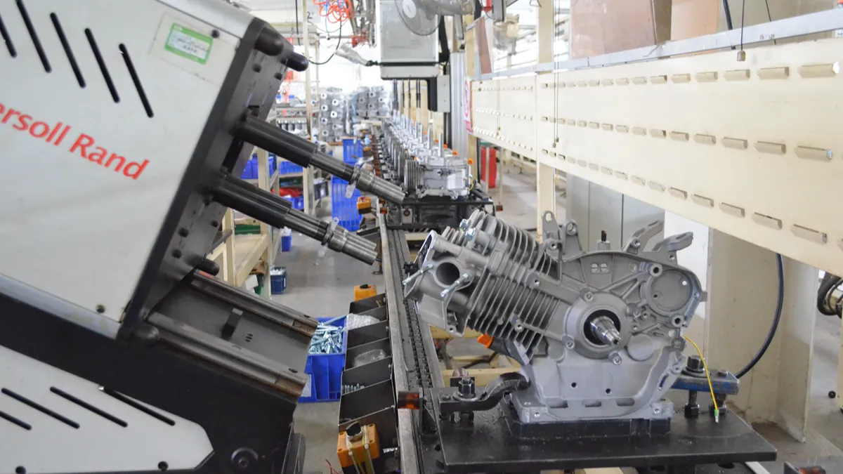
Stage 1: Metal Casting for High-Strength Engine Components

Every chainsaw starts with a strong foundation—the engine. Before any machining or assembly begins, manufacturers create the engine’s structural components through metal casting.
The most important cast parts include the crankcase, cylinder, flywheel, clutch drum, and other load-bearing components. These parts must withstand continuous vibration, high temperatures, and rapid engine speeds while remaining lightweight enough for comfortable operation. NOVOTOP further enhances user comfort with an integrated anti-vibration system that minimizes vibration transfer to the handles, allowing safer and more comfortable operation over long working hours. If you’re looking for a dependable chainsaw manufacturer, explore NEWTOP’s full range of professional motosserras a gasolina designed for OEM and global distribution.
Different casting processes are selected based on the component’s function:
| Casting Process | Typical Components | Main Advantages |
|---|---|---|
| High-pressure die casting | Aluminum crankcases, engine housings | Excellent dimensional accuracy, high production efficiency |
| Gravity die casting | Cylinder heads, medium-volume components | Better mechanical strength and surface quality |
| Sand casting | Large or low-volume components | Lower tooling cost and greater design flexibility |
| Investment casting | Steel clutch parts, sprockets | High precision and excellent surface finish |
Aluminum alloys are the preferred material for most engine housings because they provide an excellent balance of strength, resistência à corrosão, heat dissipation, and weight reduction. Steel or ductile iron is typically used for heavily loaded transmission and clutch components where higher wear resistance is required.
After casting, every part undergoes trimming, shot blasting, and preliminary dimensional inspection before moving to the machining department. Removing flash, burrs, and surface defects at this stage helps ensure consistent machining accuracy later in production.
Stage 2: Precision CNC Machining for Critical Parts

Casting produces the basic shape of each component, but it cannot achieve the tight tolerances required inside a modern chainsaw engine. Precision CNC machining creates the final dimensions that determine engine performance and reliability.
Computer-controlled machining centers perform multiple operations, incluindo:
- Cylinder boring
- Crankshaft journal machining
- Bearing seat finishing
- Thread tapping
- Surface milling
- Gear machining
- Drilling oil passages
Many chainsaw manufacturers use multi-axis CNC machining centers to complete several operations in a single setup, improving consistency while reducing production time.
The cylinder bore is one of the most critical machining operations. Its diameter, roundness, and surface finish directly influence piston sealing, compressão, eficiência de combustível, and engine lifespan. Even minor dimensional errors can increase friction or reduce engine performance.
After machining, coordinate measuring machines (CMM), laser measuring equipment, and precision gauges verify that every critical dimension falls within specification before parts proceed to assembly.
Stage 3: Plastic Injection Molding for Lightweight Housings
While the engine provides power, many external chainsaw components are manufactured using plastic injection molding to reduce overall weight and improve user comfort.
Typical injection-molded parts include:
- Front and rear handles
- Starter covers
- Air filter covers
- Tanques de combustível
- Oil tanks
- Chain brake housings
- Side covers
- Protective guards
Engineering plastics such as PA6, PA66, ABS, polypropylene (PP), and glass fiber reinforced nylon are commonly used because they offer high impact resistance, excellent dimensional stability, and resistance to fuel, óleo, and UV exposure.
The injection molding process consists of several stages:
- Plastic pellets are heated until molten.
- The material is injected into precision molds under high pressure.
- Cooling channels solidify the plastic rapidly.
- Parts are automatically ejected from the mold.
- Gates and flash are removed before inspection.
Modern production lines often use robotic systems for automatic part removal and trimming, improving production efficiency while maintaining consistent quality.
Each molded component is inspected for sink marks, warpage, flash, and dimensional accuracy before entering the final assembly line.
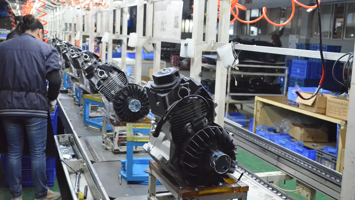
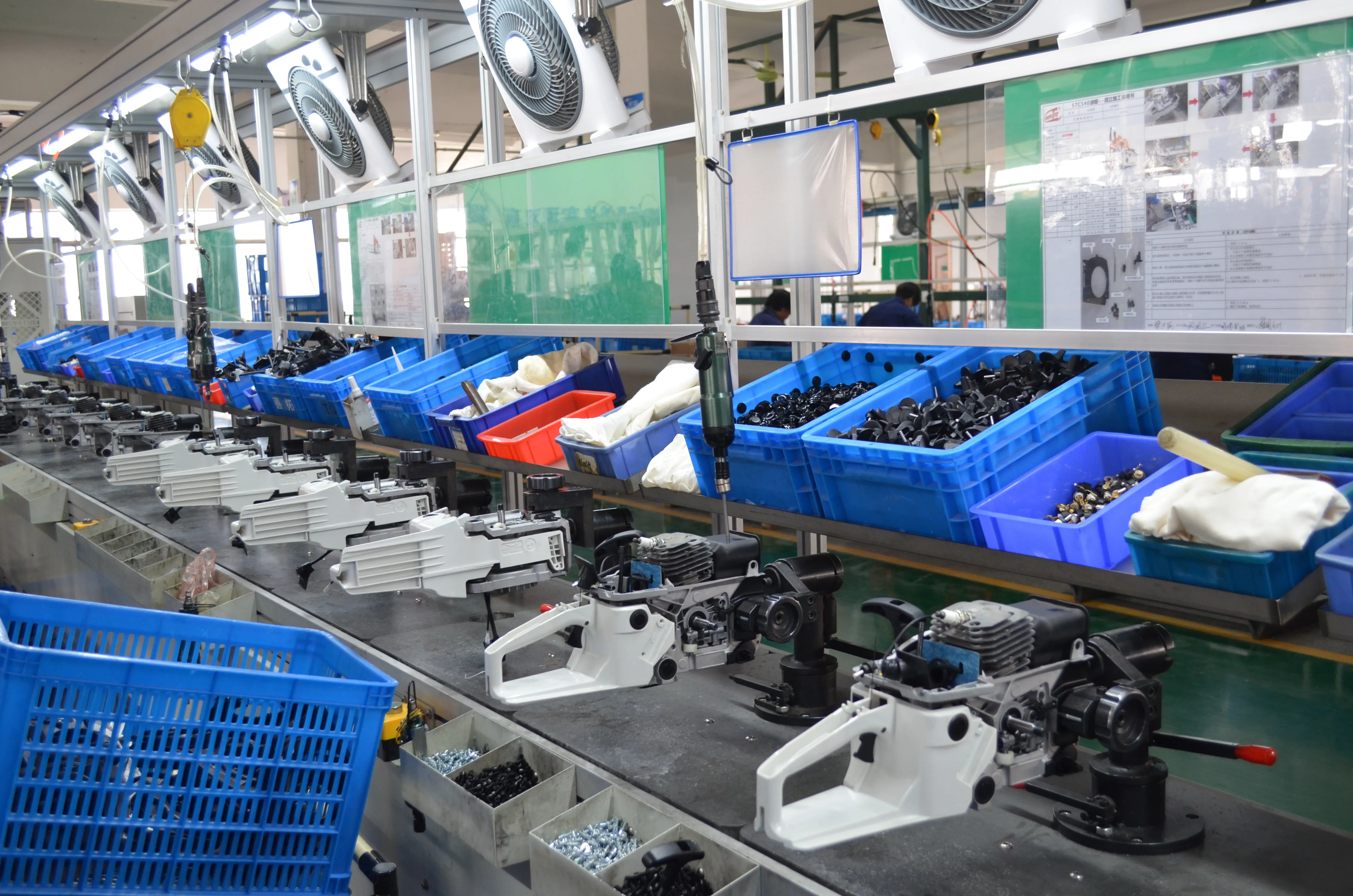
Stage 4: Engine Assembly and Power System Integration

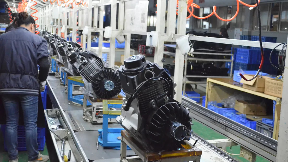
Once all engine components have been manufactured, technicians assemble the complete power unit according to carefully controlled procedures.
A typical assembly sequence includes:
- Installing crankshaft bearings
- Press-fitting the crankshaft
- Installing the piston and piston rings
- Connecting the connecting rod
- Mounting the cylinder
- Installing seals and gaskets
- Assembling the ignition system
- Installing the carburetor
- Mounting the clutch and flywheel
After engine assembly, ignition timing, carburetor settings, and compression are checked before the power unit advances to final product assembly.
Modern production lines also use barcode or QR code tracking to record assembly data, allowing every engine to be traced throughout its manufacturing history.
Maximize Margins With Premium Garden Machinery
Stage 5: Manufacturing the Guide Bar and Saw Chain
The guide bar and saw chain form the cutting system of a chainsaw and require specialized manufacturing processes separate from engine production.
Guide Bar Manufacturing
Guide bars are typically produced from high-strength alloy steel through:
- Steel blanking
- Heat treatment
- Groove machining
- Nose sprocket installation (for sprocket nose bars)
- Grinding
- Surface coating
- Final inspection
Heat treatment increases hardness while maintaining enough toughness to resist bending and cracking during heavy cutting.
Saw Chain Manufacturing
Saw chains are significantly more complex than they appear. A single chain contains hundreds of precisely manufactured components, incluindo:
- Cutter teeth
- Drive links
- Tie straps
- Rebites
Each cutter tooth is stamped, heat treated, precision ground, and sharpened to produce consistent cutting performance.
Automated riveting machines assemble individual links into complete chains while maintaining accurate chain pitch and articulation. After assembly, chains are lubricated, tension-tested, and inspected for smooth operation.
High-quality chains often feature chrome-plated cutter teeth and hardened rivets to improve wear resistance and extend service life.
Stage 6: Final Assembly, Performance Testing, and Quality Inspection

The final stage brings together every component into a finished chainsaw ready for shipment.
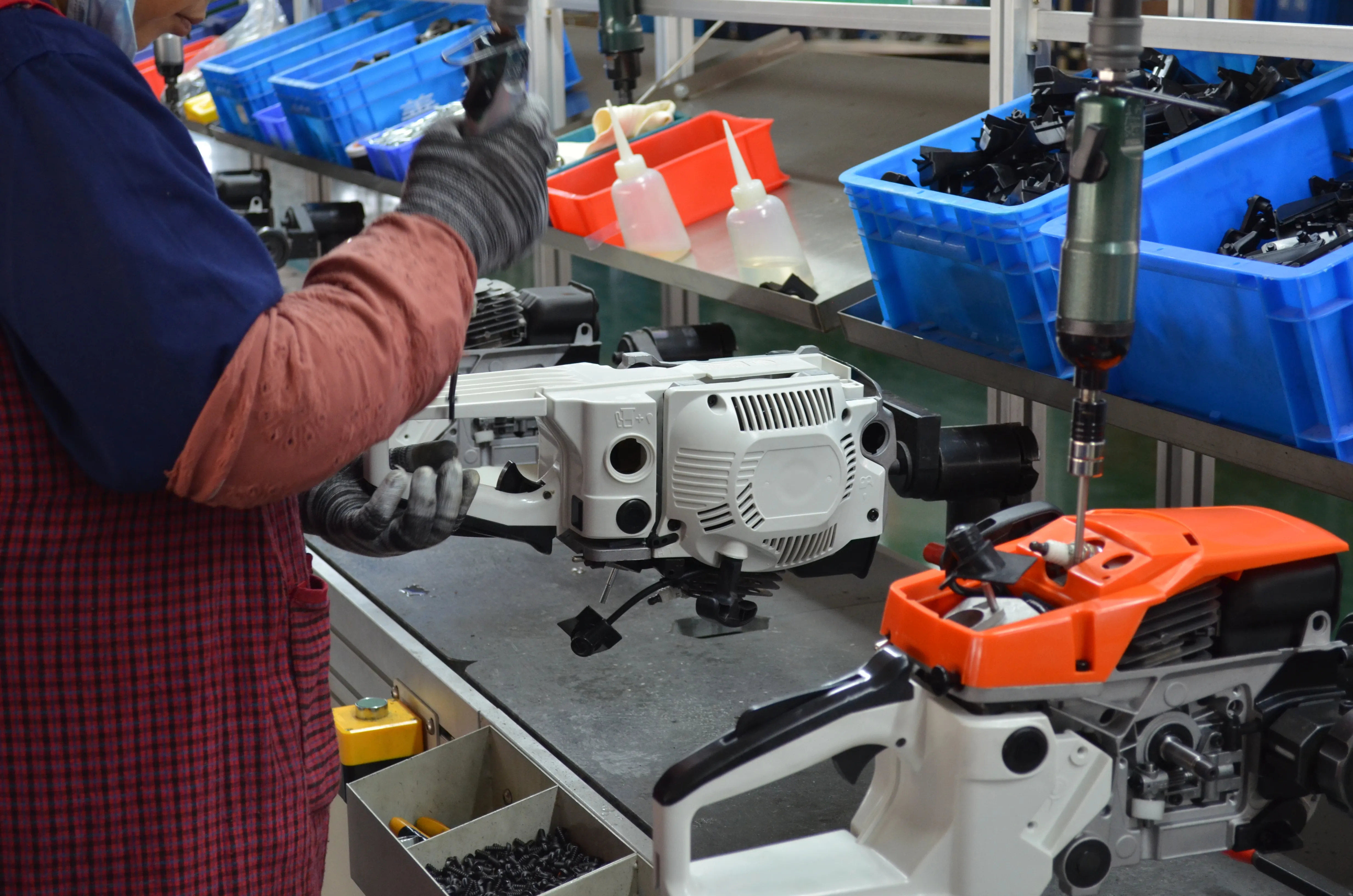
During final assembly, workers install the completed engine, barra guia, corrente de serra, plastic housings, sistema de combustível, ignition components, alças, safety devices, and control mechanisms.
Each chainsaw then undergoes multiple quality inspections before packaging.
Typical production tests include:
| Inspection Item | Propósito |
|---|---|
| Torque verification | Ensure fasteners meet assembly specifications |
| Compression test | Verify engine sealing performance |
| Ignition test | Confirm reliable spark generation |
| Fuel system leak test | Prevent fuel leakage |
| Chain brake test | Verify operator safety |
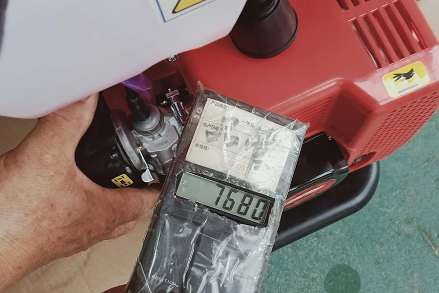
| Idle speed test | Ensure stable engine operation |
| Maximum RPM test | Confirm engine performance |
| Noise and vibration test | Evaluate operating comfort |
| Visual inspection | Check cosmetic quality and assembly accuracy |
Em NEWTOP, every chainsaw model undergoes rigorous endurance testing of up to 200 horas under demanding operating conditions. Built with high-quality components and strict manufacturing standards, NEWTOP chainsaws are engineered to deliver more than 500 horas of working life under professional use, providing reliable performance for forestry, paisagismo, e aplicações comerciais.
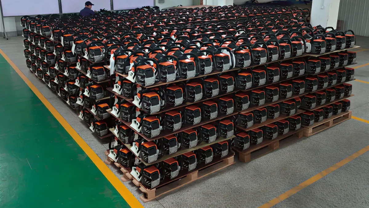
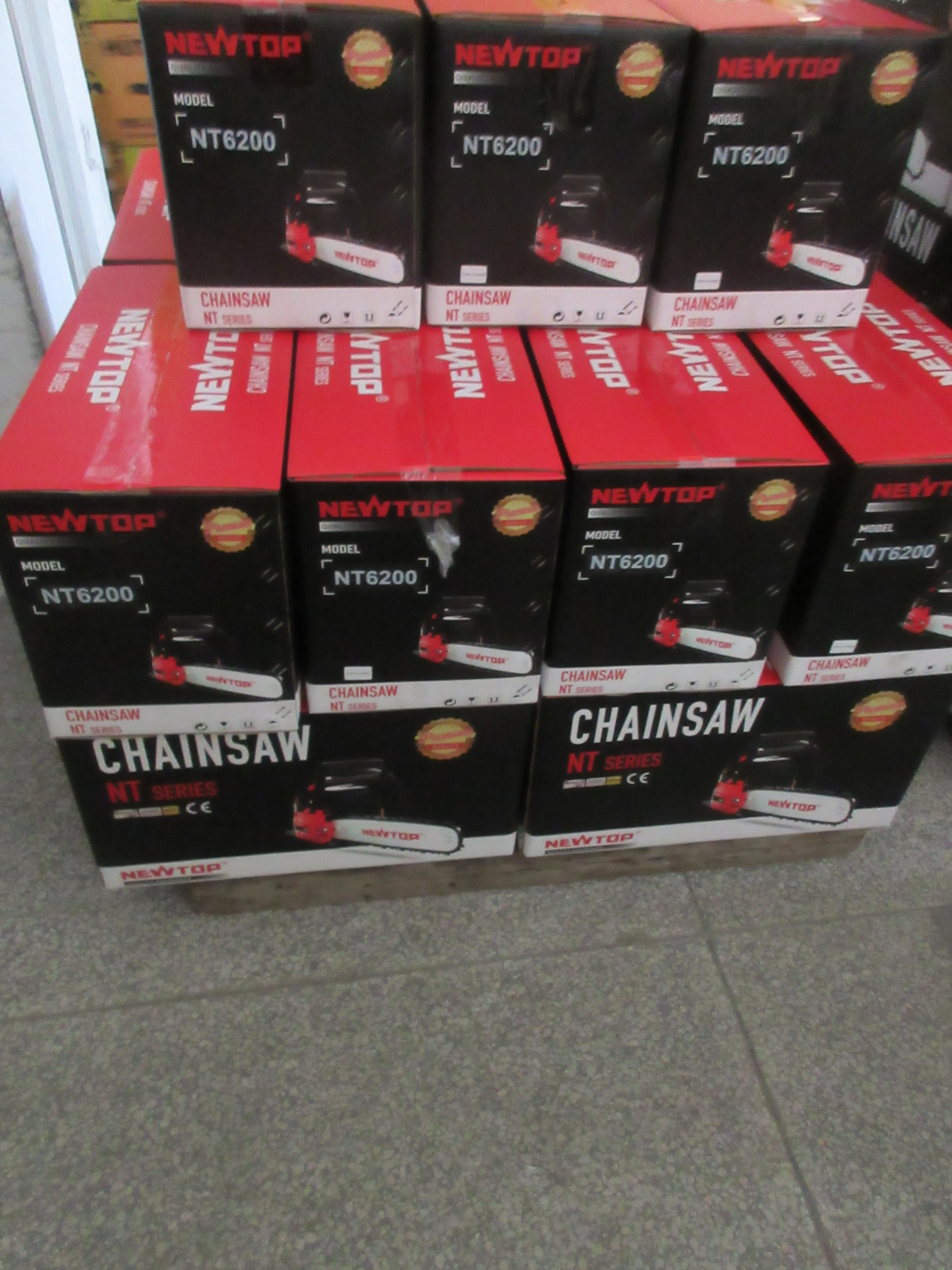
Only after passing all inspection procedures are chainsaws cleaned, packaged with accessories and manuals, and prepared for shipment.
What Certifications and Standards Should a Chainsaw Factory Meet?
Certifications demonstrate that a reliable chainsaw manufacturer follows internationally recognized quality, segurança, and environmental requirements.
Depending on the target market, a reliable chainsaw factory should comply with standards such as:
| Certification | Propósito |
|---|---|
| ISO 9001 | Quality management system |
| CE | Compliance with European safety requirements |
| GS | German product safety certification |
| EPA | U.S. emissions compliance |
| CARBONO | California emissions standards |
| RoHS | Restriction of hazardous substances |
| REACH | Chemical safety compliance |
Em NEWTOP, quality and compliance are integrated into every stage of manufacturing. Our factory operates under an ISO 9001-certified quality management system, and our products comply with international standards and certifications, incluindo CE, GS, EPA, RoHS, and REACH, depending on the product model and destination market. This allows us to support OEM customers across Europe, América do Norte, and many other global markets with confidence.
How Quality Control Ensures Reliable Chainsaw Performance

Consistent chainsaw performance relies on strict controle de qualidade, from precise component tolerances to rigorous safety validation and independent lab testing before shipment.
| QC Phase | Key Focus Area | Primary Objective |
|---|---|---|
| Specifications | Dimensional & Material Limits | Establish production baselines. |
| Incoming QC | Bore Size & Groove Width | Block defective parts early. |
| In-Process | Mistake-proofing & PFMEA | Prevent assembly errors. |
| Final Testing | Velocidade de corte & Segurança | Validate functional performance. |
Establishing Technical Specifications and Supplier Standards
Quality control begins long before parts hit the assembly line. Manufacturers rely on detailed technical documents to set exact boundaries for what constitutes an acceptable component. This foundation dictates how the supply chain operates and prevents vague standards from degrading the final product.
- Defining dimensions: Engineering teams set precise dimensional tolerances for cylinders, barras guia, and chains to ensure alignment and prevent vibration.
- Material selection: Production managers establish strict requirements for wear-resistant steel alloys and impact-resistant plastics to survive harsh forestry environments.
- Supplier audits: Procurement teams audit partner factories for dedicated power tool production lines, advanced CNC machining, and specialized heat treatment capabilities.
Incoming Quality Control (IQC) for Critical Components
Catching defects at the source is significantly cheaper and safer than pulling apart a finished chainsaw. Incoming Quality Control (IQC) filters out substandard raw materials and purchased parts before they compromise the powerhead or cutting system.
- Cutting attachment checks: Inspectors test guide bar groove width, rail parallelism, and chain pitch tolerances against technical drawings.
- Engine component verification: Technicians verify cylinder bore size, roundness, and piston dimensions using coordinate measuring machines.
- Hardware validation: Staff check fasteners, trigger lock-outs, and chain brake springs to guarantee safety devices will function under load.
In-Process Controls and Manufacturing Stability
High-volume production lines introduce variables that can drift over a shift. In-process controls keep manufacturing stable, isolating individual workstations to detect assembly errors the moment they happen.
- Process mapping: Engineers map manufacturing steps with PFMEA to prioritize controls on high-risk operations like clutch installation and carburetor tuning.
- Assembly aids: Operators utilize mistake-proofing jigs and go/no-go fixtures to prevent incorrect component alignment.
- Mid-line checks: QC staff conduct intermediate functional tests on engine start behavior and preliminary guide bar tracking.
Final Performance Testing and Safety Validation
Once mechanical assembly concludes, testing shifts from static dimensions to dynamic performance. Every unit or sampled batch must prove it can cut efficiently and shut down safely under simulated field conditions.
- Cutting capability: Technicians perform test cuts on standardized wood samples to verify cutting speed, smoothness, and chip evacuation.
- Safety systems: Inspectors validate chain brake reaction times, throttle lock-outs, and kill switch reliability.
- Visual and physical fit: QA teams check final assembly for the correct chain tension range, secure guard alignment, and overall cosmetic integrity.
Independent Verification and Documentation Standards
International buyers trust independent validation over internal factory reports. Third-party testing and rigorous documentation keep global supply chains honest and protect the brand’s reputation upon import.
- Third-party audits: Brands engage independent inspection firms for AQL pre-shipment sampling and compliance lab testing.
- Physical baselines: Production teams use approved golden samples as the ultimate reference for fit, finish, and performance.
- Strict record-keeping: Factories maintain detailed bilingual specification packs and order confirmations to eliminate ambiguity and prevent scope drift.
Why Choose NEWTOP as Your OEM Chainsaw Manufacturer?

Partnering with NEWTOP gives distributors a direct pipeline to fully certified, scalable power equipment built for immediate global market entry.
Selecting the right manufacturing partner involves more than comparing prices. A capable factory should combine engineering expertise, capacidade de produção estável, strict quality management, and responsive customer support.
No NOVOTOP, we integrate the entire manufacturing process—from component production to final assembly—to ensure consistent product quality across every order.
Our manufacturing advantages include:
- Mais do que 20 years of manufacturing experience in outdoor power equipment
- Modern production facilities with advanced CNC machining and automated assembly
- Strict quality control throughout every production stage
- Comprehensive testing before shipment
- Support for OEM and ODM customization
- Flexible production capacity for distributors and brand owners
- Global export experience across multiple international markets
Whether you are launching a new chainsaw brand or expanding an existing product line, NEWTOP can provide dependable manufacturing support, stable quality, and long-term partnership for your business growth.
Perguntas frequentes
Can a Chinese factory handle OEM chainsaw orders?
Chinese factories easily handle end-to-end OEM chainsaw production. You can expect complete support from design adaptation and power parameter tuning to custom branding and export packaging. Facilities run dedicated lines for gasoline, corded electric, and battery-powered lithium-ion models.
How long does mass chainsaw production typically take?
Mass production cycles depend on the project scope. Standard repeat batches finish in 5 para 15 days once parts arrive at the assembly line. New OEM runs requiring prototype validation and custom molds take 3 para 6 weeks. Once on the main conveyor, physical assembly and testing for a single unit take just 10 para 30 minutos.
How do manufacturers test chainsaws before shipping?
Quality control teams run chainsaws through dedicated testing workshops before packaging. They test engine seals under pressure, calibrate idle and high-speed RPM thresholds, and perform physical wood-cutting trials. Inspectors also test critical safety components, including the chain brake reaction time, throttle lock-out, and the engine kill switch.
What materials are used to ensure chainsaw durability?
Professional chainsaw production relies on high-carbon and alloy steels for guide bars and saw chains. Premium cutting teeth often feature double chrome plating or brazed carbide inserts to reduce wear. For the powerhead, manufacturers cast engine blocks from lightweight aluminum or magnesium alloys and mold outer housings from impact-resistant engineering plastics.
What certifications should I look for in a chainsaw manufacturer?
Look for factories operating under ISO 9001 quality management and ISO 14001 environmental standards. For the product itself, target markets dictate the exact requirements. European imports demand CE marking covering Machinery and EMC directives, along with noise and vibration compliance. Verified test reports from recognized labs like TÜV Rheinland provide the strongest proof of reliability.
Choosing the right outboard propeller is not simply about finding a model that fits the engine shaft. A propeller directly affects acceleration, velocidade máxima, consumo de combustível, engine load, and overall boating experience.
For boat builders, distribuidores, and marine equipment buyers, selecting the wrong propeller can lead to poor performance, excessive vibration, higher fuel costs, and even long-term engine issues.
A reliable propeller selection process should consider several factors, including engine specifications, boat characteristics, condições de operação, blade design, material choice, and supplier capability.
This guide explains the key points buyers should check before purchasing an outboard propeller and how to make a more accurate selection for different applications.
What Key Information Should You Prepare Before Choosing a Propeller?

Before comparing propeller models, collect accurate information about the engine, barco, and daily use. This reduces fitting errors and gives the supplier enough data to recommend a suitable starting configuration.
Prepare the following details:
| Data Category | Metrics to Record |
|---|---|
| Current Propeller | Diâmetro, tom, rotation, contagem de lâminas, material, hub splines |
| Engine Details | Rated HP, gearcase size, target WOT RPM, actual WOT RPM |
| Boat Profile | Comprimento (LOA), hull shape, operating weight, speed goals |
| Usage Environment | Primary activity, cruise speed, water conditions (fresh/salt/shallow) |
| Benchmarks | GPS speed at WOT, time to plane, ventilation in turns |
Current Propeller Specifications
Your existing propeller serves as the baseline for any future adjustments. You need exact numbers off the current hub or blades to know which direction to adjust your pitch or diameter.
- Diameter and pitch: Record these numbers (usually stamped on the barrel, como 14 x 19) to establish your starting point.
- Direção de rotação: Identify if the prop uses right-hand or left-hand rotation. This matters heavily for twin-engine setups.
- Blades and material: Note if you run a 3-blade or 4-blade design, and whether it is cast aluminum or stainless steel.
- Hub and shaft details: Count the splines on the prop shaft and measure the shaft diameter to ensure your replacement physically fits the gearcase.
Engine Details and WOT RPM Limits
Engine specifications define your operating envelope. Your motor has a specific RPM band where it makes peak power safely, and your prop must keep the engine inside that band.
- HP and gearcase size: Verify your rated horsepower and gearcase dimensions. These dictate which propeller families fit the outboard.
- Target WOT RPM: Find the manufacturer’s recommended Wide Open Throttle (O QUE) Faixa de rotação. Modern outboards usually target 5,000 para 6,000 RPM.
- Actual WOT RPM: Measure your current wide-open RPM under a normal load. This tells you if the engine is over-revving or lugging.
- Trim systems: Note if the boat has power trim or trim tabs. These systems dictate how you tune the hull attitude to reach optimal RPM.
Boat Characteristics and Load Profile
Hull design and operating weight directly influence thrust requirements. A heavy pontoon pushes water differently than a light bass boat, demanding a totally different blade geometry.
- Hull dimensions: Document the length overall (LOA), hull material, and bottom shape (like deep-V or flat-bottom). These dictate drag and required lift.
- Operating weight: Calculate your realistic load. Include fuel, passageiros, engrenagem, and livewells.
- Load frequency: Identify if you frequently run heavily loaded. Heavy loads often require stepping down in pitch or moving to a 4-blade prop to maintain thrust.
- Speed targets: Define your present top speed against your desired top speed. This guides the tradeoff between pitch and acceleration.
Usage Profile and Operating Environment
How and where you drive determines the optimal propeller style. You must align the design with your primary on-water activities to get the best efficiency.
- Primary use: Specify if you focus on high-speed cruising, heavy towing for watersports, or commercial work.
- Running speeds: Identify your typical throttle positions. This determines if you optimize for mid-range fuel economy or absolute top-end speed.
- Condições da água: Consider your environment. Abrasive, arenoso, or shallow waters often demand the durability of stainless steel over standard aluminum.
Real-World Performance Benchmarks
Never buy a new propeller without testing the old one first. You need hard performance data to compare against your post-installation results.
- Baseline test runs: Take the boat out and record maximum RPM and GPS speed at wide-open throttle, trimming up just before the prop cavitates.
- Acceleration metrics: Evaluate your hole shot, the time it takes to get on plane, and the boat’s ability to hold a plane at lower speeds.
- Handling checks: Monitor the steering for signs of propeller ventilation, excessive slip during hard turns, or cavitation in rough chop.
How Do Diameter and Pitch Affect Propeller Performance?

Diameter and pitch are two of the most important measurements in propeller selection. They determine how efficiently an outboard propeller converts engine power into thrust and directly influence acceleration, velocidade máxima, eficiência de combustível, and engine RPM.
Before choosing a replacement propeller, buyers should understand what these two specifications mean and how they work together. A propeller marked as 14 × 19, por exemplo, indicates a 14-inch diameter and a 19-inch pitch. The first number represents diameter, while the second number represents pitch.
For a more detailed explanation of propeller markings and how these measurements affect performance, buyers can refer to our guide on what pitch and diameter mean on an outboard propeller.
Diâmetro refers to the distance across the full circle made by the rotating blades. A larger diameter generally produces more thrust because it moves more water with each rotation.
Large-diameter propellers are commonly used for:
- Heavy boats
- Commercial applications
- Boats that require strong pulling power
- Low-speed operation
A smaller diameter propeller usually allows higher RPM and may support better top-speed performance on lightweight boats.
Tom refers to the theoretical distance a propeller moves forward in one complete rotation without considering slip. Por exemplo, a 19-inch pitch propeller is designed to move approximately 19 inches per rotation under ideal conditions.
The relationship between pitch and performance is:
| Pitch Choice | Performance Effect |
|---|---|
| Tom mais baixo | Aceleração mais rápida, stronger thrust, easier engine operation |
| Tom mais alto | Higher potential speed, lower RPM, suitable for light loads |
No entanto, increasing pitch does not always increase speed. If the pitch is too high, the engine may struggle to reach its recommended RPM range, causing poor acceleration and increased stress.
A proper selection balances pitch, diâmetro, engine power, and boat load. Many buyers use factory recommendations as a starting point and then adjust based on real operating conditions.
Source Durable Garden Machinery at Competitive Prices
How Does the Number of Blades Influence Speed, Impulso, e eficiência de combustível?
Blade count dictates the balance between top speed and load capacity. Fewer blades reduce drag for maximum speed, while more blades provide necessary grip for heavy loads.
The Relationship Between Blade Area and Drag
Every propeller blade moving through water creates surface friction and pressure drag. Fewer blades result in a smaller total wetted area, directly translating to lower hydrodynamic drag and higher potential open-water efficiency.
Adding blades increases the Blade Area Ratio (BAR). A higher BAR gives the propeller significantly more grip on the water, reducing slip and ventilation. The trade-off is higher hydrodynamic interference between the blades, demanding more power to turn at the exact same RPM.
How Blade Count Affects Top Speed
Two-blade propellers theoretically offer the highest top speeds on lightly loaded hulls because they encounter minimal drag. For most recreational planing hulls, three-blade designs hit the sweet spot. A well-matched three-blade propeller consistently runs 5% para 10% faster at wide-open throttle compared to a four-blade setup.
Upgrading to a four-blade propeller usually cuts peak speed by about 2 para 3 mph. Yet, these high-blade configurations maintain effective speed much better in rough water or high-trim conditions by actively resisting blowout.
Thrust Capabilities and Load Management
Total thrust depends heavily on the total blade area. A propeller with fewer blades forces each blade to carry a higher unit thrust. Push a low-blade-count prop too hard under a heavy load, and you risk severe cavitation or structural stress at the blade root.
Four-blade and high-BAR three-blade propellers excel at managing demanding workloads. You need these configurations for:
- Heavy Boats: Lifting heavy hulls onto plane quickly.
- Towing Applications: Delivering strong mid-range acceleration.
- Limited Clearances: Maximizing thrust when gearcase size limits the maximum diameter.
Fuel Efficiency and Optimal Engine Loading
For standard recreational setups, a correctly sized three-blade propeller delivers the best steady-cruise fuel economy. The minimal drag allows the outboard to run efficiently near its peak torque band.
Adding a fourth blade increases the physical load on the engine. You almost always need to drop the pitch to keep the wide-open throttle RPM within the manufacturer’s optimal range. On heavily loaded boats, a four-blade propeller can actually improve real-world fuel efficiency. By drastically reducing slip, it holds the boat on plane at lower RPMs, burning less fuel than a three-blade prop struggling to grip the water.
Should You Choose an Aluminum or Stainless Steel Propeller?

Aluminum offers budget-friendly protection for shallow waters and lower horsepower, while stainless steel delivers speed, grip, and durability for high-performance outboards and saltwater environments.
For buyers who want to understand the detailed differences between these two materials, including strength, durabilidade, manutenção, and application scenarios, our guide on aluminum vs stainless steel outboard motor propellers provides a complete comparison.
Matching Material to Outboard Horsepower
Outboard horsepower directly dictates the ideal propeller material. For motors under 30 HP, manufacturers almost exclusively equip factory aluminum propellers. Stainless steel options in this range remain scarce and offer little practical performance benefit.
Mid-range engines between 30 e 70 hp pair perfectly with aluminum for general recreational boating. The power output at this level rarely causes severe blade flex, keeping performance stable for everyday use. Once you step up to outboards producing 75 hp and above, the operating dynamics change. These engines generate high torque and push heavier loads, making stainless steel the standard choice to handle the increased thrust without losing blade shape.
Durability and Lower Unit Risk
How a propeller reacts to underwater impacts determines the safety of your lower unit gears. You must evaluate your primary operating environment before making a choice.
- Sacrificial protection: Aluminum acts as a sacrificial component, bending or cracking upon impact to absorb shock and protect lower unit gears.
- Impact transfer: Stainless steel withstands normal wear and minor impacts, but transfers heavy strike forces directly to the prop shaft.
- Shallow hazards: Boaters navigating shallow, stump-filled, or rocky rivers should select aluminum to minimize expensive gearcase repairs.
- Saltwater endurance: Marine environments heavily favor stainless steel due to its superior long-term corrosion resistance.
Hydrodynamic Performance and Handling
Material stiffness heavily influences thrust efficiency. Manufacturers cast aluminum blades thicker to achieve necessary strength, but they still flex under heavy loads. This flexing slightly reduces top-end speed and high-RPM stability. Stiff, thin stainless steel blades maintain their precise pitch and shape under pressure, improving thrust efficiency and maximizing water displacement.
Upgrading to a stainless steel model often yields a 2 para 3 mph speed gain alongside stronger acceleration for heavy loads. Stainless steel also holds cupping better than aluminum. This structural advantage ensures reliable grip during tight turns and drastically reduces ventilation issues on the water.
Cost Comparison and Lifespan Value
An aluminum propeller costs roughly one-third the price of a comparable stainless steel model. Budget-conscious buyers and boaters who frequently replace damaged props benefit the most from this low upfront cost. The inexpensive replacement strategy makes sense when striking rocks or stumps is a routine risk.
Stainless steel requires a much higher initial investment. It provides exceptional lifespan in deep, obstruction-free waters where impact damage is rare. The long-term value quickly shifts to stainless steel for performance rigs, as the durable material eliminates the need for frequent replacements and maintains optimal fuel efficiency over thousands of hours of use.
How Do Engine Horsepower and Gear Ratio Affect Propeller Selection?

Horsepower dictates the maximum propeller size an engine can efficiently turn, while gear ratio determines shaft speed. Junto, they establish the exact pitch required to hit target WOT RPM.
The Role of Engine Horsepower in Propeller Sizing
Engine horsepower sets the baseline power budget for moving a boat efficiently. A higher horsepower rating allows an outboard to turn a larger diameter or a higher-pitch propeller without struggling. Buyers must match the propeller to the engine’s usable horsepower at the intended operating RPM, rather than looking strictly at peak horsepower marketing numbers.
If you choose an oversized or over-pitched propeller, the engine will lug and fail to reach its intended power band. Undersize the propeller, and the engine will over-rev, leaving valuable performance unused and risking mechanical damage.
How Gear Ratio Determines Propeller Shaft Speed
Gear ratio acts as a primary input that fundamentally changes the final propeller load. It is not just a secondary detail. You calculate propeller shaft RPM directly by dividing the engine RPM by the gear ratio.
A higher numerical gear ratio reduces the prop shaft speed and multiplies torque. To restore the desired boat speed, this setup requires a higher-pitch propeller. Por outro lado, a lower numerical gear ratio spins the propeller faster at a given engine RPM, requiring reduced pitch to prevent the engine from over-revving.
Balancing Pitch and Final RPM for Optimal Performance
Adjusting the gear ratio triggers a chain reaction in pitch selection. Increasing a gear ratio numerically usually requires stepping up the propeller pitch by two to four sizes. Since a single pitch size change typically alters engine speed by 250 para 350 RPM, pitch adjustments serve as the ideal mechanism for fine-tuning wide-open-throttle (O QUE) RPM.
Operating conditions also alter this power dynamic. Heavy boat loads and high elevations demand less pitch to keep the engine from dropping below its optimal power band. For high-RPM outboard designs, manufacturers frequently use reduction ratios of 2.3:1 or higher to properly manage the aggressive propeller shaft speed and hydrodynamic load.
Practical Selection Steps for Outboard Buyers
Start the selection process by identifying the engine’s rated horsepower, gear ratio, and recommended WOT RPM range. De lá, execute a systematic testing sequence to dial in the correct specifications:
- Baseline Selection: Select a propeller size that lets the engine reach target RPM under expected load, elevação, and water conditions.
- Pitch Adjustment: Reduce pitch if the engine fails to reach target RPM, or increase pitch if the engine over-revs during initial testing.
- Sea Trial Verification: Conduct a final loaded test run to account for specific real-world variables like hull drag, running weight, and ventilation behavior.
How Does Boat Type Influence the Right Propeller Choice?

Hull design and typical boat load dictate required thrust and RPM. Matching pitch and diameter to your specific vessel type prevents engine lugging and maximizes hydrodynamic efficiency.
High-Speed Planing and Performance Boats
Luz, performance-focused hulls like bass boats or sport rigs require setups that minimize drag once on plane. Your primary goal is converting engine torque directly into top-end speed while keeping the outboard near its maximum RPM limit.
To achieve this, operators utilize higher pitch and moderate-to-smaller diameter profiles. High-speed setups rely heavily on 3-blade stainless steel propellers, which deliver the durability and thin-blade efficiency needed to push past 50 mph without flexing.
Watersports and Tow-Sport Configurations
Pulling wakeboarders, skiers, or heavy tubes demands a massive initial surge of thrust. Absolute top speed takes a backseat to a strong hole shot and smooth mid-range pulling power.
Tow boats require lower pitch and larger diameter profiles to move heavily ballasted setups without dropping below the engine’s power band. Owners frequently utilize 4-blade propellers to improve low-speed handling, reduce slip, and keep the boat securely on plane.
Pontões, Tritoons, and Heavy Cruisers
These vessels push a massive amount of water. High frontal drag and heavy, variable passenger loads mean your propeller must maximize water displacement rather than chase speed.
Pontoons and heavy cruisers benefit from larger diameter and moderate-to-low pitch to generate adequate low-speed thrust. This exact configuration prevents engine lugging and ensures the motor reaches its specified WOT RPM despite the heavy structural drag.
General Fishing and All-Purpose Vessels
Aluminum fishing boats and versatile center consoles operate across diverse conditions. The ideal setup balances rapid acceleration, mid-range cruise efficiency, and precise low-speed maneuverability around docks or structure.
Most operators pair moderate pitch with 3-blade designs to achieve versatile performance during long runs. When conditions dictate, shifting to 4-blade setups provides better grip offshore or improves shallow-water stern lift on flats boats.
Sailboats and Displacement Hulls
Displacement hulls cannot exceed their theoretical hull speed regardless of applied power. Propeller selection must focus entirely on low-speed thrust and reliable maneuvering in tight quarters.
Operators use large-diameter, low-pitch profiles to push displacement hulls efficiently at modest engine speeds. This approach protects auxiliary outboards from overloading when fighting strong currents or heavy headwinds.
What Operating Conditions Should Buyers Consider?
Propeller selection requires analyzing actual boat weight, typical water conditions, engine RPM limits, and horsepower output to prevent drivetrain damage and maximize fuel efficiency.
Boat Load and Usage Patterns
Evaluating typical operating loads is the first step in propeller selection. A boat behaves entirely differently when running solo compared to a hull weighed down by passengers, heavy gear, full fuel tanks, or towing duties.
Always prop the boat so the engine reaches the upper end of its wide-open-throttle (O QUE) rpm range when lightly loaded. This rpm buffer prevents the engine from lugging once you introduce heavy weight.
- Variable Usage: Boats shifting between light solo fishing trips and fully loaded family cruising require either a compromise propeller or a dedicated two-prop setup.
- Heavy-Duty Operations: Towing, rescue, and workboats demand high, continuous thrust. These roles favor larger diameter, lower-pitch propellers designed to run efficiently at lower rpm.
Engine RPM Matching and Performance Goals
The propeller acts as the final gear ratio between the engine and the water. It must keep the outboard operating inside the manufacturer-specified WOT rpm range. Operating outside this band degrades fuel efficiency and accelerates mechanical wear.
Pitch adjustments directly dictate engine speed. Increasing pitch by one inch typically decreases WOT rpm by approximately 200 rpm, while decreasing pitch raises it by the same amount.
- Planing Hulls: These setups require rapid hole shot and target a controlled slip factor of 8-15% at WOT for peak efficiency.
- Displacement Hulls: Slow-speed vessels ignore top-end speed to focus entirely on generating maximum low-end torque.
- Real-World Validation: Empirical WOT testing with proper trim adjustments is the only reliable way to validate rpm matching and fuel burn under actual operating conditions.
Water Environment and Surface Conditions
The physical water environment dictates blade geometry. Rough water causes the hull to pitch, increasing the risk of the propeller breaking the surface. Propellers with increased blade area or aggressive cupping hold water better and reduce ventilation in heavy chop.
Calm water applications allow operators to take the exact opposite approach, prioritizing higher pitch and lower drag designs to push top-end speed.
- Hazardous Environments: Shallow or debris-filled waters guarantee eventual bottom strikes. These areas require durable materials and responsive motor trim capabilities to protect the drivetrain.
- Water Flow Quality: Propellers require clean, undisturbed water to generate optimal thrust. Poor mounting heights or excessive hull turbulence will cause aeration and immediate power loss.
Outboard Horsepower and Structural Demands
Engine output strictly determines the required material strength. High-horsepower outboards, typically rated at 140 hp and above, exert extreme torque that overwhelms weaker metals and causes aluminum blades to flex.
Rigid stainless steel propellers are the primary choice for high-output engines. Stainless maintains its exact designed geometry under heavy loads and high speeds, providing predictable thrust and maximum traction.
- Lower-Horsepower Applications: General-purpose and lower-hp engines perform exceptionally well with aluminum propellers. They offer a cost-effective, impact-forgiving alternative that acts as a sacrificial part during bottom strikes.
- Exhaust Compatibility: You must verify the propeller design integrates correctly with the lower unit’s specific exhaust routing, particularly for through-hub exhaust systems.
What Common Propeller Selection Mistakes Should Buyers Avoid?
Avoiding common propeller selection mistakes—like guessing pitch, ignoring typical loads, or neglecting lower unit fitment—saves fuel, protects the engine, and prevents costly on-water failures.
Misjudging RPM, Tom, and Load Requirements
Buyers often sabotage outboard performance by selecting a propeller without validating how it impacts the engine’s actual operating range.
- Ignoring the WOT RPM range: Failing to match the propeller to the engine’s recommended Wide Open Throttle (O QUE) limits causes the engine to lug under heavy load or over-rev at top speed.
- Prioritizing theoretical top speed: Selecting pitch just to hit a high top-speed number ignores the inverse effect pitch has on RPM and low-end acceleration.
- Testing on an empty boat: Finalizing a prop choice with a light hull gives false data. The boat will struggle to plane once fully loaded with passengers, engrenagem, and fuel.
Treat the manufacturer’s specified WOT RPM as a hard constraint. You must hit this target under normal, real-world operating loads to ensure efficient running and long engine life.
Overlooking Blade Count and Material Trade-Offs
Many buyers mistakenly believe that simply adding blades or buying the cheapest material will fix performance issues. Every design change shifts the performance curve.
- Assuming more blades equal better performance: Buyers often switch from three to four blades hoping for an outright upgrade, not realizing the extra drag typically drops WOT RPM by 50 para 150 rpm.
- Shopping by material price: Choosing aluminum over stainless steel strictly to save money ignores your actual environment. Soft aluminum deforms under high load, while stainless steel maintains its shape and efficiency at high speeds.
- Ignoring the primary use case: Buying a propeller designed for fast, solo runs fails if you spend 80% of your time towing wakeboarders or carrying a heavy crew.
Match the blade geometry and material to your actual daily environment. A high-performance stainless steel prop shines in open water but transfers severe shock to the gearcase if you strike a submerged stump in shallow rivers.
Using Flawed Testing and Adjustment Methods
Troubleshooting a sluggish boat requires a systematic approach. Guessing at propeller specs without proper baseline data leads to wasted money and unresolved engine strain.
- Changing multiple variables at once: Swapping pitch, contagem de lâminas, and material in a single step makes it impossible to isolate which change improved or hurt performance.
- Ignoring GPS boat speed: Focusing strictly on tachometer readings without verifying actual speed hides secondary issues like extreme prop slip.
- Blaming the prop prematurely: Buyers often fault the propeller for sluggish planing when the real culprit is excessive hull drag, the wrong engine mounting height, or poor trim angle.
Establish a clear baseline with your current setup first. Make single, incremental adjustments—usually starting with pitch—and test the results on the water before changing another variable.
Neglecting Fitment, Manutenção, and Spares
Even the perfectly pitched propeller fails if it does not physically integrate with the outboard gearcase or lacks basic maintenance.
- Guessing hub compatibility: Buying a prop without checking spline counts, hub system types, or matching thrust washers leads to stripped splines and lower unit damage.
- Ignoring physical damage: A slightly bent blade or fishing line wrapped around the prop shaft mimics the symptoms of incorrect pitch.
- Running without a spare: Operating without a backup prop leaves you stranded after a severe strike and eliminates your ability to swap to a lower-pitch prop for unexpectedly heavy loads.
Verify fitment against the engine transom tag before purchasing. Inspect the prop hub assembly periodically to catch early signs of slippage or corrosion.
Considerações Finais
Buyers should evaluate engine specifications, tipo de barco, condições de operação, blade design, material choice, and supplier reliability when bulk buying outboard motor propellers.
The right propeller improves acceleration, eficiência de combustível, manuseio, e desempenho do motor, while the wrong choice can reduce efficiency and increase operating costs.
Para distribuidores, boat manufacturers, and marine equipment companies, working with an experienced outboard propeller supplier provides better product consistency and long-term support.
With advanced manufacturing capability, precision-balanced aluminum and stainless steel propellers, and OEM/ODM production experience, NEWTOP helps global partners develop reliable propeller solutions for different marine applications.
Perguntas frequentes
What should I check before buying an outboard propeller?
Verify your boat’s primary use, typical load profile, and desired performance goals. You must confirm engine specifications, including the brand, horsepower, shaft type, and the manufacturer’s recommended wide-open-throttle (O QUE) Faixa de rotação. Collect baseline data from your current prop, such as diameter, tom, material, and observed WOT RPM, to guide your replacement choices.
How do I choose the right propeller pitch?
Selecting pitch relies on matching the propeller to your engine’s recommended WOT RPM range. Test your current setup at full throttle with a normal load. If the RPM falls below the recommended band, decrease the pitch. If the RPM exceeds the limit, increase the pitch. Changing the pitch by one inch generally alters the engine speed by 150 para 200 RPM.
Is stainless steel better than aluminum for all users?
Não. Stainless steel provides superior rigidity, higher top speeds, and excellent saltwater corrosion resistance, making it ideal for high-horsepower engines. Aluminum is highly cost-effective and serves as a sacrificial metal. In shallow or hazard-prone waters, an aluminum propeller will bend or break upon impact, which helps protect the expensive gearcase from severe damage.
What is the best propeller for heavy boats?
Heavy vessels require maximum static thrust and control rather than high top speed. The best approach is selecting a larger diameter propeller with a lower pitch to ensure the engine reaches its target RPM under heavy load. A four-blade design is frequently recommended to improve grip, accelerate planing, and provide smoother handling in rough conditions.
How do I confirm hub compatibility?
Read your engine’s transom tag to find the exact make, modelo, ano, and gearcase code. Match this data against the new propeller’s specifications, ensuring the spline count and shaft diameter align perfectly. You also need to identify whether your outboard uses a fixed splined bore or a modular insert kit, and verify the proper thrust washer sequence.
What documents should a propeller supplier provide?
A standard procurement package should include a Certificate of Conformance (CoC), material certificates, and final inspection or balance reports. For commercial or classed vessels, suppliers must also provide traceability records and relevant approval documents to prove the delivered hardware meets the required engineering standards.
How important is sample testing before a bulk order?
On-water sample testing is critical because catalog specifications cannot predict how a hull and engine combination will react to complex loads. Testing a small batch validates WOT RPM, manuseio, e eficiência de combustível. Skipping this step risks large-scale inventory issues, engine mis-loading, and severe cavitation problems across the fleet.
What if my engine does not reach recommended RPM with the new prop?
Failing to reach the specified WOT RPM range typically means the boat is over-propped, placing excessive mechanical stress on the engine. If the fuel and ignition systems are healthy, correct the issue by switching to a propeller with a lower pitch or a smaller diameter. A one-inch pitch reduction generally increases engine speed by roughly 150 para 200 RPM.
An outboard propeller works in one of the harshest environments on a boat. Every trip exposes it to sand, rocks, floating debris, shallow water, and continuous high-speed rotation. The challenge is that propeller damage often develops slowly. A tiny chip today may become a crack tomorrow, while slight vibration can eventually damage bearings, selos, or even the lower unit. Learning how to recognize the early warning signs helps boat owners avoid expensive repairs, improve fuel economy, and maintain safe performance on the water.
Neste guia, you’ll learn the most common signs of outboard propeller damage, how to inspect your propeller correctly, when repairs are practical, and when replacement is the better long-term solution.
Why Early Propeller Damage Detection Matters
Direct Performance and Efficiency Impacts
A compromised propeller immediately degrades how your vessel moves through the water. Minor blade distortions force the engine to work outside its optimal load range, dragging down overall performance.
- Disrupted hydrodynamics: Damaged blades alter water flow, resulting in lower top speeds and weaker acceleration.
- RPM restrictions: Altered effective tom prevents the engine from hitting its designated wide-open throttle RPM.
- Fuel waste: Reduced propeller efficiency forces the outboard to work harder, significantly increasing fuel consumption.
- Vibration and handling: Imbalanced blades induce vibration that impairs steering precision and degrades overall ride comfort.
Preventing Secondary Mechanical Failures
Ignoring a damaged propeller transfers stress directly to your outboard’s internal drivetrain. What starts as a bent blade quickly compromises seals and bearings deep inside the lower unit.
- Contaminated gear oil: Unnoticed cracks near the submerged fin often cause water ingress and gear oil contamination.
- Engine stress: Deformed propellers alter engine load, causing harmful under-revving or over-revving that stresses internal components.
- Accelerated fatigue: Continuous vibration from an imbalanced prop accelerates structural fatigue in gearcase bearings, driveshafts, and engine mounts.
- Overheating risks: Combined with restricted water inlets, poor propeller condition elevates the risk of severe engine overheating.
Vessel Safety and Operational Reliability
Propeller condition dictates your physical control over the vessel. Failing to spot damage early puts both crew and cargo at risk during critical maneuvers.
- Sudden propulsion loss: A progressively failing hub or weakened blade can fracture under load, causing an immediate loss of usable propulsion.
- Collision hazards: Degraded handling and delayed acceleration reduce maneuverability around obstacles, increasing collision risks.
- Schedule integrity: Timely detection minimizes unscheduled downtime, protecting schedule integrity for commercial, charter, and rescue operations.
The Economic Case for Early Intervention
A lógica financeira é direta. Swapping a damaged propeller costs a fraction of the repair bills required if you leave a compromised unit attached to your motor.
- Low-cost intervention: Propeller inspection and replacement represent a fraction of the cost of total engine or lower unit repairs.
- Halting financial bleed: Catching damage early halts compounding financial losses from excess fuel burn and accelerated part wear.
- Avoiding major rebuilds: Ignoring early indicators frequently leads to expensive gearcase rebuilds, seal replacements, and powerhead repairs.
The First Visible Signs of Outboard Propeller Damage

Early detection of outboard propeller damage—like minor nicks, paint wear, or slight bends—prevents escalating fuel costs, vibration-induced drivetrain wear, and sudden propulsion failure.
Paint Deterioration and Superficial Scratches
We often dismiss worn paint as normal wear and tear, but localized paint wear on the blades or hub points to frequent minor impacts with sand or small debris. It acts as the first warning sign before structural bending occurs.
You will typically notice fine scratches appearing on the leading edge first. These surface abrasions usually precede deeper structural wear. Once the protective coating strips away, the exposed bare metal patches create immediate vulnerabilities for accelerated corrosion in saltwater environments.
Nicks, Chips, and Minor Dents
A perfectly smooth edge is essential for hydrodynamic efficiency. Small chips along the leading edge disrupt water flow and increase the risk of cavitation. This turbulent water causes pressure drops that erode the surrounding metal.
Shallow dents on the blade surfaces serve as the earliest structural deformities detectable without specialized tools. Look closely at the trailing edge during inspections. Early material loss at the trailing edge directly impacts the grip and lift of the propeller, which reduces your acceleration and top-end speed.
Subtle Blade Deformation and Bending
Propellers operate under immense load, and even a slight geometric change throws off the balance of the entire drive system. Slightly bent blade tips clearly indicate previous contact with rocks or a hard bottom.
To spot these issues, view the propeller straight from the front. Visible asymmetry suggests uneven deformation from one-sided impacts. Micro warping or twisting alters the pitch and load distribution across the blades. This forces the engine to burn more fuel to maintain your normal cruising speed.
Localized Corrosion and Cavitation Pitting
Material degradation compromises the strength of the unit. Small corrosion pits or powdery white oxidation on aluminum propellers mark areas of material weakening. These spots quickly expand if left unchecked.
Rough, sandblasted patches near high-load regions indicate early cavitation erosion. As vapor bubbles collapse against the metal, they blast away the surface layer. Repeated erosion gradually thins out sections near the leading edge, making them prone to cracking during high-RPM operation.
Visible Hub Misalignment and Scoring
The hub absorbs shift shock and acts as the critical link between the engine and the blades. Scoring or distortion around the hub collar hints at abnormal stress or improper installation. You can test the integrity of the internal rubber bushing with a quick visual diagnostic.
Draw a straight line across the hub and barrel, run the boat under load, and check the marks. Misaligned diagnostic marker lines visually confirm internal hub slippage. You should also check for flattened or peened edges, which reflect a history of running the outboard through shallow, rocky water.
Source High-Margin OEM Garden & Maquinaria agrícola
How Vibration, Barulho, and Poor Acceleration Reveal Damage

Propeller damage rarely announces itself with a catastrophic failure. It subtly degrades hydrodynamics, sending mechanical warnings through vibration, unusual noise, and sluggish performance that operators must decode.
The Mechanics of Propeller-Induced Vibration
Even minor propeller damage immediately disrupts hydrodynamic balance. When blades hit underwater objects, bent edges or missing metal shift the center of mass off the rotational axis. This mechanical imbalance forces the driveline to absorb cyclical stress.
- Center of mass shift: Bent blades or chipped edges create a mechanical imbalance away from the rotational axis.
- Hydrodynamic distortion: Altered blade geometry changes lift and thrust, placing uneven loads on the shaft and gears.
- RPM sensitivity: Vibrations peak at low to mid RPMs when the propeller works hardest to push the boat onto plane.
- Feedback transmission: Cyclical imbalances travel straight through the propshaft into the steering wheel, transom, and deck.
Translating Noise into Specific Driveline Issues
An outboard should produce a steady acoustic profile under load. When a propeller sustains damage, it introduces turbulence and mechanical interference that change the sound signature completely.
- Cavitation sounds: Damaged blades create low-pressure zones that spawn cavitation bubbles, producing distinct crackling, buzzing, or hissing noises.
- Engine stutter: Uneven thrust generation forces the motor to pulse audibly during hard acceleration runs.
- Lower unit rattle: Impact forces transfer directly into the lower unit, making gears and bearings rumble as they absorb the shock.
- Secondary wear indicators: Prolonged operation with an unbalanced prop causes propshaft bearings to grind or gearcases to emit a high-pitched whine.
Recognizing Performance Loss and Sluggish Acceleration
Physical damage directly compromises grip in the water. This hydrodynamic inefficiency forces the engine to burn more fuel while delivering less forward momentum.
- Increased propeller slip: Physical damage stops the efficient conversion of engine torque into actual forward thrust.
- Weak hole shot: A sluggish transition to plane serves as the primary indicator of blade distortion.
- Speed reduction: Minor imperfections trigger measurable drops in top speed and alter operating RPMs at specific throttle settings.
- Baseline comparison: Comparing current speed and wide-open throttle (O QUE) RPM against historical metrics isolates propeller inefficiency from actual engine power loss.
Diagnostic Steps to Confirm the Root Cause
You cannot fix a driveline issue based purely on operator feel. Technicians rely on a strict diagnostic sequence to separate propeller damage from internal engine faults.
- Visual inspection: Check the blades thoroughly for bends, nicks, gouges, rachaduras, or unequal marine growth.
- Shaft examination: Look at the prop shaft for visible bends, binding during manual rotation, or fishing line cutting into the seals.
- Isolation test: Run the engine safely in gear without the propeller installed to see if the vibration stops.
- Secondary component check: Evaluate engine mounts and fuel delivery systems if symptoms persist after installing a known-good propeller.
How to Inspect Blade Edges, Hub Area, and Shaft Contact

A systematic inspection of blade geometry, hub integrity, and shaft contact points prevents catastrophic lower unit failures, stops vibration, and ensures peak propulsive efficiency.
| Inspection Zone | Key Defect Indicators | Functional Impact |
|---|---|---|
| Blade Edges | Nicks, inward cracks, flattened cup | Hydrodynamic imbalance, cavitation, thrust loss |
| Hub Assembly | Extruded rubber, misaligned marker lines | Spun hub, complete loss of drive under load |
| Shaft & Hardware | Twisted splines, worn thrust washer | Fretting, gearcase vibration, thread damage |
Blade Edges and Surface Integrity
The geometry of the propeller blade dictates thrust generation and fuel efficiency. Technicians must examine leading edges, trailing edges, and tips for nicks, chips, gouges, or inward-radiating cracks. A damaged or flattened cupped trailing edge directly reduces water hold and increases the risk of early cavitation.
- Profile Consistency: Verify uniform rake angle and pitch across all blades to identify uneven bending or impact damage.
- Balance Check: Mount the propeller horizontally on a hub rod to identify heavy or off-plane blades.
- Clearance Limits: Ensure a minimum 3 mm tip clearance from the anti-cavitation plate to prevent contact under heavy load or blade flex.
Hub Area and Spun Hub Detection
The hub handles the brutal torque transfer from the engine to the water. A compromised rubber bushing acts as a failed mechanical fuse, dropping propulsion completely. Inspectors should check the outer hub barrel and blade roots for dents, ovalization, ou rachaduras na linha do cabelo. Extruded, melted rubber or heat staining clearly signals a failed bushing.
- Slippage Diagnostic: Draw a marker line across the outer housing, rubber zone, and inner hub, then run the boat under load to check for misalignment.
- Exhaust Path: Inspect internal routing for carbon build-up or structural obstructions that could disturb exhaust flow.
Prop Shaft and Hardware Contact Zones
The connection between the propeller and the driveline must remain perfectly aligned to avoid transferring destructive vibrations into the gearcase. Assess the propeller shaft for straightness, runout, ferrugem, and signs of pitting. Spline teeth on both the shaft and the hub bore require close inspection for rounding, chipping, or twisted profiles.
- Thrust Washer Integrity: Examine seating surfaces for cracks, uneven wear, or deep grooves that throw off propeller alignment.
- Torque Application: Apply the proper manufacturer-specified torque—commonly 40-60 ft-lbs—to prevent fretting or thread damage.
Integrated Inspection Workflow
A standard inspection workflow brings these discrete checks into a repeatable process. You must disable the engine ignition, remove the locking hardware, and safely slide the propeller off the shaft. Cleaning the shaft and hub bore with a degreaser is critical to accurately assess the splines and thrust washer without old marine grease hiding the defects.
- Component Evaluation: Systematically check the hub for spun bushing signs and the blade edges for profile consistency.
- Reassembly Protocol: Reinstall using fresh marine grease, pushing the prop forward until it clicks firmly against the thrust washer.
- Final Securing: Torque the nut to spec and verify the locking hardware is properly engaged.
When Minor Damage Can Still Be Repaired

Minor propeller damage like edge burrs and shallow nicks can be repaired with basic filing, provided the blade geometry remains intact and no cracks or vibration are present.
Identifying Repairable Minor Damage
Before breaking out the tools, you need to confirm the damage is actually minor. Repairable defects are strictly surface-level flaws that do not compromise the structural integrity or hydrodynamic shape of the propeller.
- Surface-level dings: Small burrs, leading-edge nicks, and dents that leave the original blade geometry intact.
- Isolated edge wear: Damage limited entirely to the blade edges, meaning the overall diameter and pitch remain unchanged.
- Smooth operation: Propellers that continue to push the boat efficiently without inducing unusual vibration.
- Structural soundness: A complete absence of visible cracks or physical deformation during visual inspection.
If the propeller still performs well and the shaft runs true, you are likely dealing with cosmetic or minor edge wear.
Indicators of Severe Damage
Not all impacts result in a quick fix. Some structural flaws demand immediate professional intervention or a complete replacement to protect your gearcase.
- Visible cracks: Fractures in the blade or hub area, which usually require professional welding or replacement.
- Blade deformation: Noticeable bending or twist across one or multiple propeller blades.
- Severe vibration: Shaking immediately following an impact, signaling a potential mass imbalance.
- Drivetrain impact: Damage extending to the prop shaft, seal, or gear case after a hard strike.
- Die-cast limitations: Die-cast propellers displaying structural flaws, as marine professionals routinely classify these as non-repairable.
Operating with any of these severe defects transfers immense stress directly to your lower unit bearings and seals.
DIY Repair Methods and Discipline
Fixing minor edge damage requires precision and restraint. The goal is to smooth the water flow, not redesign the blade.
- Clean the propeller: Remove all marine growth, sujeira, and oil to accurately assess the damage profile.
- File flat: Gently use a coarse or mill bastard file, keeping the tool flat to avoid reshaping the blade.
- Minimize removal: Take off only the absolute minimum amount of metal necessary to smooth out the burr or nick.
- Know when to stop: Cease filing the exact moment the raised metal disappears to preserve blade balance and efficiency.
- Polish the edge: Refine the filed area with fine sandpaper and polish it to reduce hydrodynamic drag and resist corrosion.
Over-filing a single blade shifts the center of mass, transforming a simple nick into a permanent vibration problem.
Deciding Between Repair and Replacement
Knowing when to stop trying to salvage a damaged propeller saves money and prevents unexpected breakdowns on the water.
- Owner repairs: Best suited for slight burrs and minor dings that need only light, controlled filing.
- Professional shops: Necessary for straightening bends, balancing, and checking for hidden cracks using dye or probe scanning.
- Replacement threshold: The smarter financial choice if repair costs exceed 50% of the propeller’s total replacement value.
- Spare recovery: Keeping a spare propeller onboard acts as the ultimate fail-safe if minor damage rapidly worsens during a trip.
Treat your propeller as a consumable wear part. Upgrading to a new unit is significantly cheaper than rebuilding a blown gearcase caused by running an unbalanced prop.
When Early Replacement Is the Safer Choice
Certain types of damage should not be repaired because they increase the risk of sudden failure.
Replacement is usually recommended under the following conditions.
| Damage Type | Replace Immediately? | Reason |
|---|---|---|
| Large blade cracks | Sim | High risk of blade separation |
| Missing blade section | Sim | Severe imbalance |
| Bent propeller shaft | Sim | Can damage gearbox |
| Multiple damaged blades | Sim | Difficult to restore accurately |
| Severe corrosion | Sim | Reduced structural strength |
| Repeated repaired cracks | Sim | Metal fatigue continues to grow |
Choose NEWTOP for Reliable Outboard Propeller Performance
A durable propeller begins with dependable manufacturing. No NOVOTOP, we produce precision-balanced aluminum and stainless steel outboard propellers designed to deliver stable performance, smooth operation, and long service life across a wide range of marine applications.
Our manufacturing process combines advanced CNC machining, strict dimensional inspection, dynamic balancing, and comprehensive quality testing to ensure every propeller meets consistent performance standards before shipment. Whether you need replacement propellers for aftermarket distribution or OEM production for your own brand, NEWTOP offers flexible manufacturing solutions backed by reliable capacidade de produção and global export experience.
As principais vantagens incluem:
- CCS and ECE certified quality for reliable performance and international market requirements.
- Premium materials — aluminum propellers use specially formulated aluminum-magnesium alloy for high strength and toughness, while stainless steel propellers use duplex stainless steel with better yield strength and corrosion resistance.
- Integrated molding technology — propeller blanks are formed with dedicated molds without welding, improving structural strength and durability.
- Precision hub pressing and CNC machining — one-piece pressed hubs improve dynamic balance, while CNC-machined blades ensure consistent geometry and stable thrust performance.
If you’re looking for a trusted outboard motor propeller manufacturer for wholesale supply or customized production, contact NEWTOP today. Our engineering and production teams are ready to help you select the right propeller solution for your market while ensuring consistent quality and long-term supply.
Perguntas frequentes
Como posso saber se minha hélice externa está danificada?
Look for visible bends, chips, rachaduras, or missing material on the blades. Operational signs include the engine revving unusually high without proportional boat acceleration, which often points to a spun hub. You might also notice persistent vibration, metallic noises, or a loss of steering stability at normal cruising speeds.
Can a small nick on a propeller cause vibration?
Sim, even a small nick alters the mass distribution and hydrodynamic symmetry of the blade. This physical imbalance generates centrifugal forces that manifest as noticeable vibration, often within a specific RPM band. Ignoring minor damage leads to progressive wear on the prop shaft and lower unit bearings.
What does a spun prop hub feel like?
A spun hub feels like the boat is slipping in the water. The engine RPM spikes sharply under throttle, but the boat’s speed does not increase. It mimics the sensation of a slipping automotive clutch and is sometimes accompanied by a sudden loss of thrust or a burnt rubber smell.
Should I repair or replace a chipped propeller?
Repair is usually viable for small edge chips or minor bends, especially on higher-value stainless steel props. Replace the propeller if it has large missing chunks, deep cracks near the root, or if you use a low-cost aluminum unit where repair expenses exceed half the price of a new replacement.
Can propeller damage reduce fuel efficiency?
Damaged blades increase hydrodynamic drag and disrupt smooth water flow, forcing the engine to work harder to maintain speed. This mechanical inefficiency prevents the motor from operating in its optimal RPM band, directly resulting in higher fuel consumption per nautical mile.
What kind of noise does a damaged propeller make?
A compromised prop typically produces a rhythmic knocking or thumping sound synchronized with engine RPM. You may also hear metallic rattling or a harsh, low-frequency drone from the lower unit, especially under heavy acceleration or during sharp turns.
Can I still run a boat with a bent propeller?
You should only operate a boat with a bent propeller at minimal idle power to safely return to the dock. Running at planing speeds with unbalanced blades creates severe radial loads that quickly destroy the prop shaft, rolamentos, and gearcase seals.
How often should I inspect my propeller?
Perform a quick visual and tactile check before and after every trip to spot obvious bends, chips, or wrapped fishing line. Complete a full removal inspection—taking the prop off to check the shaft, inspect seals, and re-grease the splines—at least once a season or every 100 hours of operation.
Muitos proprietários de barcos não percebem danos na hélice até que seu barco comece a parecer diferente. Talvez a aceleração fique mais lenta, custos de combustível aumentam, ou o volante começa a vibrar após atingir uma rocha escondida ou detritos flutuantes. Conhecer os primeiros sinais de alerta pode ajudá-lo a evitar reparos dispendiosos e manter seu motor de popa funcionando com eficiência.
Neste guia, vamos explicar o 5 sinais mais comuns de danos hélice externa, por que eles são importantes, e quando é hora de substituir sua hélice.
Por que uma hélice danificada nunca deve ser ignorada

Ignorar uma hélice danificada transforma pequenas perdas de eficiência em graves danos à caixa de engrenagens, custos de combustível disparados, e problemas de manuseio perigosos. Corrija-o antecipadamente para proteger seu motor e sua carteira.
Degradação de desempenho e problemas de tratamento
Uma hélice danificada prejudica imediatamente o desempenho projetado do seu barco. Mesmo pequenas distorções da lâmina arruínam o perfil hidrodinâmico necessário para converter a potência do motor em movimento de avanço eficiente. Os operadores geralmente percebem isso como um tiro lento e uma queda perceptível na velocidade máxima.
- Perda de impulso: Lâminas tortas ou lascadas perturbam a geometria, reduzindo o impulso para a frente e causando fraca aceleração.
- Lidando com a instabilidade: Superfícies irregulares da lâmina criam impulso irregular, levando à tração da direção, guarnição instável, e rastreamento inconsistente.
- Geração de vibração: A rotação desequilibrada cria vibrações sob carga, muitas vezes sentido como uma batida rítmica no convés em velocidades de planeio.
Aumento do consumo de combustível e custos operacionais
Operar uma hélice comprometida ataca diretamente seu orçamento operacional. Imperfeições na superfície da lâmina destroem o fluxo laminar de água, substituindo-o por arrasto e turbulência. O motor precisa queimar significativamente mais combustível apenas para atingir sua velocidade de cruzeiro padrão.
- Adicionado arrasto: Lâminas danificadas induzem fluxo turbulento, forçando o motor a trabalhar mais para manter o impulso.
- Maior queima de combustível: Uma hélice amassada ou torta aumenta rotineiramente o consumo geral de combustível em aproximadamente 10%.
- Compensação do acelerador: Os operadores naturalmente pressionam o acelerador com mais força para compensar o empuxo ineficiente, multiplicando silenciosamente os custos de funcionamento diários.
Estresse mecânico severo na unidade inferior
Danos cosméticos no exterior muitas vezes escondem destruição mecânica severa no interior. Uma hélice desequilibrada age como um martelo contra o seu sistema de transmissão. Ele envia constante, tensão cíclica diretamente na unidade inferior, transformando um conserto de hélice barato em uma enorme reconstrução da caixa de engrenagens.
- Desgaste da caixa de engrenagens: Carregamento irregular transmite tensão diretamente para a unidade inferior, destruindo engrenagens, rolamentos, e eixos prematuramente.
- Degradação do selo: A vibração persistente rompe as vedações do eixo de transmissão, permitindo que o óleo da engrenagem vaze e a água entre.
- Desalinhamento do eixo: Impactos fortes que deformam as pás frequentemente dobram o eixo da hélice, garantindo falha catastrófica se não for controlada.
Riscos de segurança e potencial encalhe
Operar com uma hélice danificada empurra suas margens de segurança para a zona vermelha. A perda de empuxo limpo torna a embarcação imprevisível em espaços apertados ou condições adversas. Empurrar um sistema de transmissão comprometido para o exterior é um convite a falhas mecânicas repentinas quando você mais precisa de energia.
- Riscos de atracação: A perda de impulso reverso e o manuseio errático matam seu controle de manobra em canais apertados e deslizamentos.
- Risco de avaria: Correr com danos existentes aumenta drasticamente suas chances de uma falha mecânica repentina durante o andamento.
- Vulnerabilidade climática: A eficiência de propulsão reduzida compromete suas margens de segurança ao navegar em mares agitados, ventos fortes, ou correntes fortes.
5 Sinais de uma lista de hélices externas danificadas

Se o seu motor externo vibrar de repente, perde velocidade, ou consome mais combustível do que o normal, sua hélice já pode estar danificada. A tabela abaixo resume os sintomas mais comuns, suas prováveis causas, e como eles podem afetar seu motor.
| Sinal de alerta | Causa Primária | Risco Imediato |
|---|---|---|
| Vibração | Lâminas tortas ou cubo solto | Falha na vedação da caixa de engrenagens |
| Perda de velocidade / Pobre tiro no buraco | Cubo girado ou arrasto da lâmina | Carregamento do motor |
| Barulho / Instabilidade de direção | Lâminas assimétricas ou eixo torto | Danos na engrenagem da unidade inferior |
| Alto uso de combustível / Carregar | Arrasto hidrodinâmico | Desgaste do pistão e do sistema de refrigeração |
| Danos Visíveis | Ataques de impacto | Cargas de choque para o sistema de transmissão |
Sinal 1: Vibração durante aceleração ou cruzeiro
Uma hélice danificada raramente gira corretamente. Você notará um tremor sentido diretamente no leme, a carcaça do motor externo, ou o próprio casco do barco, especialmente ao acelerar ou manter uma velocidade de cruzeiro constante. Essa vibração reduz drasticamente a eficiência da hélice e coloca pressão imediata nos suportes do motor e nas vedações da caixa de engrenagens.
- Causas Comuns: Lâminas tortas ou empenadas, um cubo solto, ou detritos pesados ao redor do eixo de transmissão.
- Verificação acionável: Desligue o motor e inspecione a hélice. Observe os ângulos da lâmina para garantir que eles correspondam, em seguida, gire a hélice manualmente para detectar qualquer oscilação ou raspagem na caixa de engrenagens.
Sinal 2: Perda de velocidade e tacada ruim
Aceleração lenta, um tempo visivelmente mais lento para entrar no avião, e redução da velocidade máxima apontam diretamente para a ineficiência da propulsão. Mesmo que a rotação do motor permaneça normal ou elevada, uma hélice comprometida não consegue converter essa potência em impulso para frente. Isso geralmente resulta da cavitação em torno das bordas das lâminas danificadas ou de incrustações marítimas pesadas, criando excesso de arrasto.
- Indicador de cubo girado: Se a bucha interna falhar, não pode transmitir o torque total do motor para a água, causando altas RPMs com movimento mínimo do barco.
- Verificação acionável: Compare seu atual acelerador totalmente aberto (O QUE) RPM e velocidade máxima em relação aos dados históricos de linha de base da sua embarcação.
Sinal 3: Ruído incomum ou instabilidade de direção
Novo zumbido, chocalho, ou ruídos de trituração indicam um grave desalinhamento mecânico, especialmente ao virar ou passar por faixas específicas de RPM. Você também pode notar que o leme parece mais difícil de dirigir ou puxa fortemente para um lado. Isso acontece porque a assimetria, lâminas dobradas geram impulso irregular, forçando o barco fora de seu caminho natural.
- Ameaça da caixa de engrenagens: O desgaste persistente geralmente indica um eixo de transmissão torto ou danos na engrenagem da unidade inferior devido a um ataque subaquático anterior.
- Verificação acionável: Mexa a hélice para frente e para trás para detectar folga excessiva. Gire-o manualmente e ouça atentamente qualquer som interno de raspagem.
Sinal 4: Maior uso de combustível e carga anormal do motor
Uma queda repentina na eficiência de combustível significa que você para no cais de combustível com mais frequência para exatamente as mesmas rotas e cargas. O arrasto hidrodinâmico causado por danos ou incrustações na lâmina força o motor a trabalhar mais apenas para superar a perda de empuxo e vibração. O motor parecerá tenso e exigirá configurações de aceleração mais altas para manter velocidades normais de cruzeiro.
- Desgaste de longo prazo: A operação sustentada sob essas condições de carga pesada acelera o desgaste dos pistões, rolamentos, e sistemas de refrigeração externos.
Sinal 5: Lâmina Visível, Eixo, ou dano de borda
Defeitos físicos são os indicadores mais óbvios de um impacto. Uma rápida inspeção visual geralmente revela dings, são dicas, pedaços faltando, ou rachaduras na linha do cabelo. Esses defeitos geralmente resultam do encalhe do barco ou do impacto em rochas, bancos de areia, recifes, ou detritos submersos. Mesmo pequenos danos físicos alteram a inclinação e o equilíbrio efetivos da hélice, transmitindo cargas de choque prejudiciais diretamente para sua unidade inferior.
- Verificação acionável: Remova a hélice para inspecionar todas as superfícies de perto. Substitua a unidade se encontrar danos estruturais graves ou se as estimativas de reparo excederem 50% do custo de um novo adereço.
Fonte de hélices externas OEM de alto desempenho
Como proteger seu motor substituindo a hélice certa a tempo

Uma hélice danificada força o motor a trabalhar mais e corre o risco de falha grave no sistema de transmissão. A substituição de uma unidade comprometida protege imediatamente sua caixa de engrenagens e restaura a eficiência de combustível básica.
Identificando quando é hora de substituir
Saber exatamente quando trocar uma hélice evita que pequenos desgastes se transformem em falhas mecânicas. As inspeções visuais e táteis atuam como sua primeira linha de defesa. Qualquer ataque contra um objeto submerso requer atenção imediata, mesmo que o barco ainda se mova.
- Danos estruturais visíveis: Verifique se há rachaduras profundas, grandes pedaços perdidos, lâminas severamente dobradas, ou bordas finas que comprometem a geometria da lâmina.
- O desempenho da linha de base cai: Fique atento a um motor que repentinamente não consegue atingir sua linha de base com o acelerador totalmente aberto (O QUE) RPM ou velocidade máxima sob cargas normais.
- Problemas de vibração e manuseio: Vibração persistente, tração de direção, ou rastreamento aproximado indica uma hélice desequilibrada.
- Verificação pós-impacto: Sempre remova a hélice para inspecionar o eixo e a vedação após atingir rochas subaquáticas, registros, ou detritos.
Escolhendo a Hélice de Substituição Correta
Instalar uma hélice incompatível é tão prejudicial quanto operar uma hélice quebrada. Você precisa alinhar a especificação de substituição com seu tipo de casco e carga operacional típica.
- Passo e diâmetro corretos: A falta da faixa de inclinação recomendada pelo fabricante força o motor a acelerar demais ou atrasar, destruindo a economia de combustível e aceleração.
- Alumínio para absorção de impacto: Os suportes de alumínio atuam como uma barreira sacrificial em águas rasas, águas densas em perigo. Eles se deformam com o impacto, transmitindo muito menos choque para a cara caixa de engrenagens.
- Aço inoxidável para durabilidade: Escolha aço inoxidável quando precisar de máxima eficiência, resistência flexível, e durabilidade em águas profundas ou sem perigo.
Verificações de instalação e pós-substituição
Uma substituição bem-sucedida requer atenção rigorosa à montagem do cubo e ao ambiente do eixo. Antes de deslizar a nova hélice, limpe completamente e prepare a área para garantir que a transmissão funcione corretamente.
- Preparação do eixo: Retire a linha de pesca enrolada, ervas daninhas, e detritos que podem cortar a nova vedação.
- Assentos de ferragens: Aplique graxa de grau marítimo nas estrias. Prenda a porca de suporte com a especificação exata de torque sem apertar demais, e insira uma cupilha nova se o projeto exigir.
- Teste de fricção: Coloque o motor de popa em ponto morto e gire a nova hélice manualmente. Ele deve girar livremente sem emperrar ou raspar a caixa de engrenagens.
- Verificação de linha de base: Opere o barco sob carga normal para confirmar se a nova hélice restaura sua velocidade máxima original e WOT RPM.
Conclusão

Inspeções regulares e substituição oportuna são as melhores maneiras de proteger seu motor de popa, melhorar o desempenho da navegação, e reduzir custos operacionais a longo prazo. É igualmente importante adquirir hélices de motor externo com o passo correto, diâmetro, e materiais de alta qualidade para garantir uma operação confiável e eficiente.
Esteja você substituindo hélices para sua própria frota ou adquirindo produtos para sua empresa, a parceria com fabricantes experientes de hélices para motores de popa pode fazer uma diferença significativa na qualidade do produto, desempenho, e confiabilidade a longo prazo. No NOVOTOP, nossa fábrica integrada de hélices com motor de popa combina fabricação avançada com serviços flexíveis de OEM/ODM para ajudar distribuidores e marcas marítimas a ter sucesso em mercados competitivos.
👉 Entre em contato com a NEWTOP hoje para discutir seus requisitos de OEM ou atacado e receber uma cotação competitiva para seu próximo projeto de hélice externa.
Perguntas frequentes
Quais são os sinais de uma hélice externa danificada?
Você pode detectar danos à hélice através de defeitos visuais, queda de desempenho, e sintomas mecânicos. Procure por amassados, pontas de lâmina dobradas, pedaços faltando, ou rachaduras perto do hub. Na água, o dano aparece como velocidades máximas mais lentas, tiros lentos, e altas RPMs do motor com baixa velocidade de avanço do barco. Você também pode sentir novas vibrações rítmicas no leme ou ouvir ruídos fortes. Se você notar vazamento de óleo de engrenagem leitoso ao redor da unidade inferior, o impacto provavelmente comprometeu as vedações do eixo de transmissão.
Uma hélice danificada pode danificar meu motor?
Sim, uma hélice danificada causa forte estresse em todo o motor externo e na unidade inferior. Mesmo uma pequena curvatura da lâmina cria uma rotação desequilibrada. Este desequilíbrio rotacional envia contínua, vibrações pesadas diretamente através da linha de transmissão. Deixado desmarcado, esta agitação martela as vedações do eixo de transmissão até que elas falhem, deixando o lubrificante da engrenagem vazar e a água entrar. Operar o motor nesse estado leva rapidamente ao desgaste destrutivo de metal com metal em seus conjuntos de engrenagens e rolamentos.
Por que meu barco vibra depois de bater em algo debaixo d’água?
Bater em um objeto submerso desequilibra seu sistema de transmissão. O impacto geralmente entorta a pá da hélice, lascas de material, ou dobra ligeiramente o eixo da hélice. Porque a hélice não mantém mais sua forma simétrica ou gira perfeitamente, ele orbita em vez de girar suavemente. Essa oscilação gera uma força de tremor rítmica que sobe pela perna externa, através dos suportes do motor, e diretamente no casco.
Danos à hélice podem causar má aceleração?
Sim. Dano físico altera o passo da lâmina, curvatura, e xícara. Esta distorção mata a eficiência hidrodinâmica da hélice, forçando-o a perder o controle da água e reduzindo drasticamente o impulso para frente. Também, se um golpe forte danificar o cubo de borracha interno - comumente chamado de “cubo girado”—o casco da hélice desliza no eixo. Quando você pisa no acelerador, o motor gira alto enquanto o barco mal acelera ou se esforça para entrar no avião.
Uma hélice ruim aumentará o consumo de combustível?
Sim. Operar uma hélice danificada força o motor a queimar mais combustível por quilômetro. Dobrado, lascado, ou pás muito sujas criam arrasto hidrodinâmico extra e aumentam o deslizamento da hélice. Porque as pás danificadas não conseguem converter o torque do motor em empuxo de forma eficiente, o motor de popa precisa girar mais rápido e trabalhar muito mais apenas para manter sua velocidade normal de cruzeiro. Ao longo de uma temporada, esta ineficiência resulta em contas de combustível significativamente mais altas.
Por quanto tempo posso usar uma hélice danificada com segurança?
Você só deve operar uma hélice danificada por tempo suficiente para retornar à doca em baixa velocidade. Operando uma vibração, suporte desequilibrado por qualquer período prolongado coloca anormal, estresse cíclico nos rolamentos e vedações da unidade inferior. Empurrar o motor nesta condição aumenta rapidamente um simples, substituição barata da hélice em uma reconstrução catastrófica da caixa de engrenagens.
Um cubo danificado pode fazer o motor acelerar demais??
Sim. Os fabricantes projetam o cubo de borracha interno para deslizar durante um impacto severo para proteger as engrenagens da unidade inferior contra cisalhamento. Uma vez que este hub gira ou rasga, ele perde permanentemente o controle do casco externo da hélice. Quando você aplica o acelerador, o cubo danificado escorrega em vez de transferir torque. Isso permite que as RPMs do motor aumentem rapidamente sem empurrar o barco para frente, imitando a sensação de uma transmissão escorregadia.
Devo manter uma hélice sobressalente a bordo?
Manter uma hélice sobressalente a bordo é altamente recomendado. Serve como seguro barato, especialmente se você usar uma hélice de alumínio ou navegar regularmente em águas rasas, águas cheias de obstrução. Carregando uma unidade sobressalente, junto com uma chave de apoio, uma arruela de encosto de reposição, e um contrapino novo, permite que você troque o suporte danificado no local. Isso restaura a propulsão segura imediatamente e evita um fim de semana arruinado ou uma conta cara de reboque.