


- Tutto
- NEWTOP Storie di clienti
- NEWTOP Explorer Hub
- NEWTOP Approfondimenti sul settore
What is a gasoline generator? It is a portable or frame-mounted machine that uses gasoline to produce electricity when grid power is unavailable or cannot reach the working area.
The product may appear straightforward, but selecting the right one involves more than choosing a familiar model or the largest number on the label. The generator must match the equipment being powered, the electrical standards of the destination market, the expected operating conditions, and the user’s service capabilities.
Per i rivenditori, the task is broader. A generator suitable for essential household backup may not meet the demands of a workshop, farm, contractor, or small commercial facility. A practical product range needs clear differences in output, configuration, mobility, and price.
What a Gasoline Generator Can—and Cannot—Do
A gasoline generator produces electricity while its engine is running and fuel is available. Unlike a battery power station, it does not store electrical energy for later use.
Several outlets on the control panel also do not mean that every connected device can operate at the same time. All equipment shares the generator’s available output, so the combined demand must remain within its rated capacity.
A complete gasoline generator normally combines an engine, alternator, sistema di alimentazione, control panel, protection devices, and supporting frame. The engine supplies mechanical rotation, while the alternator converts that movement into electrical current.
A detailed explanation of this internal process is available in our guide, How Does a Gasoline Generator Work? Key Components and Power Generation Explained.
This article focuses on a different question: how should first-time buyers and dealers evaluate the product before ordering?
What Can a Gasoline Generator Power?
The answer depends on the generator’s rated output and which devices will operate simultaneously.
Light electrical loads may include:
- Lamps and fans
- Chargers and communication equipment
- Televisions and selected small appliances
- Office equipment and payment systems
Workshops, fattorie, and jobsites may need to operate:
- Electric drills and saws
- Water pumps
- Pressure washers
- Refrigerators or freezers
- Air compressors
- Other motor-driven equipment
Motor-driven products often require considerably more power during startup than during normal operation. Generator sizing should therefore consider both running wattage and the highest starting demand. Switching high-demand equipment on at different times can also reduce the total generator capacity required.
Before selecting an output class, identify:
- The equipment that must receive power
- Which items may run at the same time
- Their combined running wattage
- The largest starting demand
- Any equipment likely to be added later
The number of sockets is not a measure of generator capacity. It only shows how many connection points are available.
Gasoline Generator Specifications Buyers Should Check First
A product page may include dozens of specifications. The following items have the greatest influence on electrical compatibility and everyday use.
| Specification | What It Means | Perché è importante |
|---|---|---|
| Rated Output | Power intended for normal operation | Provides the basis for continuous load planning |
| Maximum Output | Temporary capacity above rated output | Helps manage brief demand peaks |
| Voltaggio | Electrical output supplied to equipment | Must match local appliances and machinery |
| Frequenza | Usually configured for a 50 Hz or 60 Hz market | Must suit the destination electrical system |
| Fase | Single-phase or three-phase output | Needs to match the connected equipment |
| Sistema di avvio | Recoil start, electric start, or both | Affects convenience and battery requirements |
| Fuel-Tank Capacity | Amount of gasoline stored onboard | Influences the time available between refueling |
| Control Panel | Outlets, switches, metri, and breakers | Must match local plug types and user expectations |
| Protection Features | Low-oil, overload, or short-circuit response | Helps protect the engine and electrical system |
| Structure | Telaio, handles, ruote, and vibration mounts | Affects transport and working stability |
Rated output should guide normal load planning. Maximum output is intended for temporary demand peaks and should not be treated as the generator’s continuous capacity.
Choosing the Right Output Range for the Market
A model number becomes useful only after the required power class has been defined.
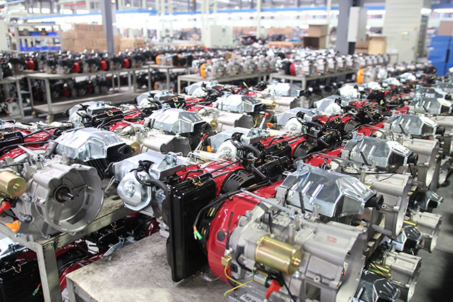
The current NEWTOP gasoline generator range includes compact 2.8 kW products, UN 5.5 kW mid-range model, UN 7.8 kW configuration, e un 10 kW high-output generator. This allows buyers and distributors to cover different load levels without positioning one machine as suitable for every user.
Compact Power: Around 2–3 kW
This range suits selected essential loads, lighter tools, and mobile work where manageable size and transport are important.
It can cover basic temporary backup or outdoor maintenance, but pumps, refrigerators, and motor-driven tools still require a starting-wattage check.
Mid-Range Power: Around 5–6 kW
Mid-range gasoline generators often cover the broadest group of users.
They can suit workshops, appaltatori, fattorie, property maintenance teams, and small commercial operations that need more capacity than a compact generator without moving into the largest portable class.
Larger Portable Power: Around 7–8 kW
At this level, customers may be planning to operate heavier equipment or several loads together.
Generator weight, wheel configuration, consumo di carburante, socket layout, phase, and starting reserve deserve closer attention. The additional output should correspond to a genuine demand rather than a preference for a larger headline number.
Potenza della benzina ad alto rendimento: Around 10 kW
Higher-output gasoline generators address users with substantial power demand who still prefer a gasoline engine and portable-frame structure.
They may suit larger workshops, construction operations, or broader backup requirements. Before ordering, confirm that the customer can manage the machine’s size, transport needs, and fuel demand.
What Changes Between Different Power Classes?
Moving from a compact generator to a 5.5 kW, 7.8 kW, O 10 kW model changes more than the available electrical output.
Engine displacement, overall weight, fuel demand, frame dimensions, starting reserve, transport arrangements, and control-panel requirements may also change. Dealers should compare the complete configuration within each power class rather than treating the kW rating as the only difference.
A distributor does not necessarily need every output level. One compact model, one core mid-range model, and one higher-output option may provide enough separation for different customer groups.
The final combination should reflect:
- Common equipment used locally
- Typical customer budgets
- Local electrical standards
- Transport and storage conditions
- Spare-parts availability
- Certification requirements
What to Confirm Before Requesting a Quotation
A request such as “send me the price for a 5 kW generator” does not give the supplier enough information to recommend the right configuration.
A more useful inquiry should include:
Destination Country
The market helps determine the required electrical configuration, socket type, etichettatura, confezione, and certification.
Equipment to Be Powered
List the main appliances, utensili, pompe, or machines. This gives the supplier more useful information than an estimated wattage alone.
Running and Starting Demand
Provide the combined continuous load and identify the equipment with the highest startup requirement.
Expected Operating Pattern
Clarify whether the generator will provide occasional emergency backup, regular daily power, or operation throughout a normal work shift.
Commercial Requirements
Include:
- Expected order quantity
- Branding requirements
- Packaging preferences
- Spare-parts needs
- Manuals and language requirements
- Target delivery schedule
The supplier can then confirm the suitable model, phase, metodo di partenza, control panel, socket configuration, and frame options.
What Dealers Should Check on a Sample Generator
A quotation sheet helps narrow the choice. A sample shows how the finished product actually starts, operates, and feels.
Starting Performance
Test cold starting and hot restarting. For electric-start models, inspect the battery arrangement and confirm whether recoil starting remains available as a backup.
Output Under Load
Do not evaluate the generator only while it runs with nothing connected. Apply an appropriate load and observe voltage, engine response, operating stability, and breaker behavior.
Response to Sudden Demand
Use suitable motor-driven equipment or controlled testing apparatus to see how the generator reacts when electrical demand rises quickly.
Control-Panel Layout
Check:
- Outlet type
- Breaker placement
- Meter visibility
- Labels and switches
- Access to the main controls
A technically suitable generator may still be difficult to sell if its control panel does not match local expectations.
Frame and Vibration
Inspect welds, fasteners, handles, ruote, rubber mounts, and movement during operation. The frame should feel stable and secure rather than loosely assembled.
Service Access
Routine maintenance areas should be reasonably easy to reach, compreso:
- Air filter
- Spark plug
- Oil filling and draining points
- Fuel valve
- Carburatore
- Batteria, where fitted
Packaging and Included Items
Confirm carton strength, internal protection, manuali, utensili, plugs, batteries, wheel kits, and any spare parts included with the shipment.
These checks provide information that may not appear in a catalog and help dealers prepare for customer service after resale.
Common First-Time Buying Mistakes
Choosing Output Without a Real Load List
Potenza nominale, simultaneous running demand, and the highest starting load should be considered together. A larger maximum-output number does not automatically make a generator more suitable.
Comparing Only Engine Horsepower
Horsepower describes the mechanical capability of the engine, not the complete electrical performance of the generator. Alternator capacity, voltage regulation, cooling, protection systems, and component matching also matter.
Treating Tank Size as Fuel Efficiency
A larger tank carries more gasoline and may extend the interval between refueling. It does not prove that the engine consumes less fuel.
Overlooking Service and Spare-Parts Requirements
A generator may suit the required load but still create difficulties if filters, starting components, control-panel parts, or common engine parts are hard to obtain.
Per i rivenditori, access to service information and replacement components is part of the product decision, not something to consider only after the first customer complaint.
A Short Safety Note
Gasoline generators produce carbon monoxide and must operate outdoors. The U.S. Consumer Product Safety Commission advises placing portable generators at least 20 feet away from homes and buildings, with the exhaust directed away from windows, doors, e prese d'aria. Generators should never operate inside homes, garages, basements, sheds, or other enclosed spaces.
The generator must be switched off and allowed to cool before refueling. CPSC also specifically warns against adding gasoline while a generator is running or hot.
Where a generator will supply building circuits, suitable transfer equipment and qualified electrical installation are required rather than an improvised connection.
Choosing a Gasoline Generator with Clear Requirements
The best model is not automatically the one with the highest output.
First-time buyers should choose around the equipment that must operate, including its running and starting demand. Dealers should build their product range around local electrical standards, common applications, price levels, and service expectations.
Once those requirements are clear, unsuitable models can be eliminated quickly. The remaining choice becomes a practical comparison of output, configuration, mobility, costruzione, e supporto post-vendita.
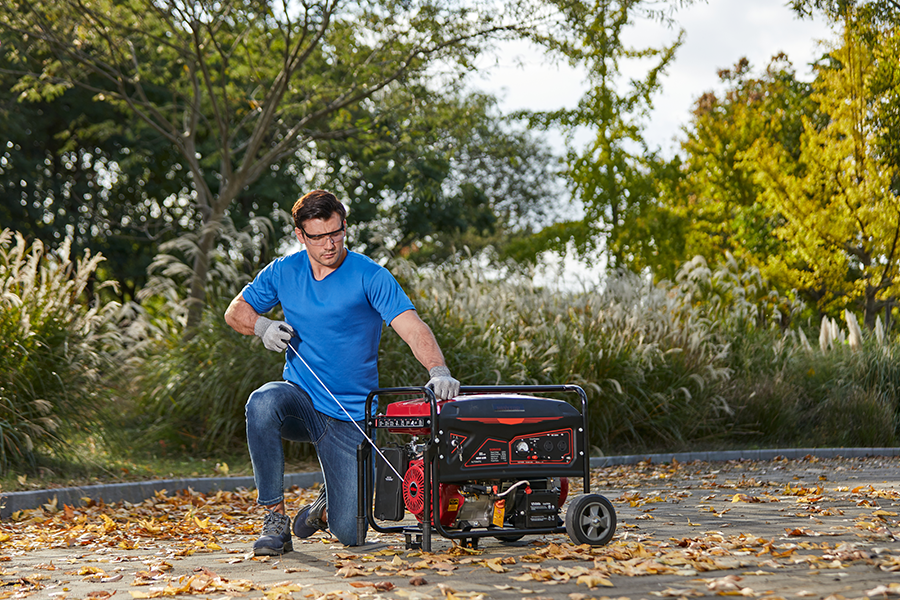
How does a gasoline generator work? It burns gasoline to create mechanical rotation, then uses an alternator to convert that rotation into electrical power.
The process involves two connected systems. The engine turns the chemical energy in gasoline into movement, while the alternator changes that movement into electricity for tools, pompe, lighting, appliances, and other equipment.
The complete energy path can be summarized as:
Gasoline → combustion → crankshaft rotation → alternator movement → electrical output
Following this path helps explain why the engine, alternator, governor, voltage regulator, cooling system, and protection devices all influence generator performance.
One Generator, Two Main Jobs
The engine and alternator are mounted on the same frame, but they perform different jobs.
IL engine produces mechanical power. It burns a mixture of gasoline and air, moves a piston, and turns the crankshaft.
IL alternator produces electrical power. The rotating crankshaft drives the alternator, where electromagnetic induction generates current.
Because these systems are separate, an engine can start and run while the outlets produce no usable electricity. In the same way, a well-made alternator cannot maintain stable output if the engine does not provide enough torque or hold the required speed.
A dependable generator needs the two systems to work as one matched power unit.
From the Fuel Tank to the Crankshaft
Gasoline first travels from the fuel tank through the fuel line and into the carburetor. The fuel system may also include a shutoff valve, filter, sediment cup, or fuel pump, depending on the generator design.
The carburetor mixes gasoline with incoming air so the engine can burn it. Before the air enters, an air filter helps prevent dust and debris from reaching the cylinder.
Many portable gasoline generators use a four-stroke engine. The operating cycle consists of:
- Assunzione: The engine draws the air-fuel mixture into the cylinder.
- Compressione: The piston compresses the mixture.
- Energia: The spark plug ignites the mixture, pushing the piston downward.
- Exhaust: Burned gases leave the cylinder.
A connecting rod transfers the piston’s up-and-down movement to the crankshaft, turning it into continuous rotation. The flywheel helps the engine maintain smooth movement between combustion strokes.
Fuel quality, air supply, ignition, lubrificazione, and internal component condition all affect how steadily this rotation can be produced.
How the Alternator Generates Electricity
The crankshaft drives the alternator rotor once the engine reaches its operating speed.
A basic electromagnetic generator contains a rotating component called the rotor and stationary insulated wire coils called the stator. As the rotor turns, its magnetic field moves relative to the stator windings, inducing electrical current. The alternator therefore converts the mechanical energy supplied by the engine into electrical energy.
The electricity then passes through the generator’s voltage-regulation, controllare, and protection systems before reaching the outlets.
Alternator construction affects how the generator manages current and heat. Winding material, insulation, rotor design, cooling, and assembly accuracy can all influence output stability and durability.
Key Components Inside a Gasoline Generator
| Componente | Main Function | Perché è importante |
|---|---|---|
| Fuel Tank and Fuel System | Store and deliver gasoline | Affect fuel flow, starting, and runtime |
| Carburatore | Mix gasoline with air | Supports stable combustion |
| Air Filter | Reduce dust entering the engine | Protects engine performance and internal parts |
| Spark Plug and Ignition System | Ignite the compressed air-fuel mixture | Affect starting and combustion stability |
| Piston and Connecting Rod | Convert combustion pressure into movement | Transfer power to the crankshaft |
| Crankshaft and Flywheel | Produce and maintain rotation | Drive the alternator |
| Governor | Respond to changes in engine speed | Helps the engine recover as load increases |
| Rotor and Stator | Generate electrical current | Form the core of the alternator |
| Voltage Regulator | Manage voltage output | Helps reduce voltage fluctuation |
| Circuit Breaker | Interrupt excessive current | Protects against overload and electrical faults |
| Cooling and Exhaust Systems | Remove heat and exhaust gases | Support safe and sustained operation |
| Frame and Vibration Mounts | Support the complete machine | Improve stability during use and transport |
This is why generator quality cannot be judged by engine horsepower alone. The engine, alternator, control system, protective components, and frame must be properly matched.
What Happens When a Load Is Connected?
A generator does not work as hard while running with nothing plugged in.
Once a tool, pompa, refrigerator, or other device is connected, the alternator begins supplying current. The electrical demand creates additional resistance against the rotor, so the engine must produce more torque to maintain speed.
The response happens quickly:
- Electrical demand rises.
- Engine speed begins to fall.
- The governor opens the throttle.
- More gasoline and air enter the engine.
- Combustion output increases.
- The engine returns toward its operating speed.
- The voltage regulator responds to the new load.
A brief change in engine sound is normal when a substantial load starts. Persistent surging, heavy voltage drop, breaker tripping, or failure to recover may point to overload, restricted fuel flow, unstable engine speed, or an electrical fault.
Rated Output and Maximum Output
Generator specifications usually show both rated and maximum output, but the two figures serve different purposes.
Rated output is the power the generator is designed to provide during normal operation.
Maximum output is temporary additional capacity that helps the generator handle short increases in demand, particularly when motor-driven equipment starts.
A generator with a 6.0 kW maximum output may not be designed to supply 6.0 kW continuously. Buyers should calculate normal demand using rated output and leave enough reserve for starting loads.
This is especially important for:
- Water pumps
- Refrigerators and freezers
- Air compressors
- Construction tools
- Electric motors
- Equipment that starts automatically
Adding only running wattage can underestimate the short surge required during startup.
How Generator Design Affects Power Delivery
Manufacturing a generator involves more than placing an engine beside an alternator.
The engine must provide enough torque for the selected alternator. The alternator must match the intended voltage, frequency, rated output, and phase. Cooling airflow must reach the major heat-producing components, while the frame and vibration mounts must keep the machine stable.
The NEWTOP NTGR6500H2 shows how these elements are combined in a gasoline generator. It uses a 389 cc, single-cylinder, air-cooled four-stroke OHV engine with a synchronous brushed SENCI copper-wire alternator. Its specifications list 5.5 kW rated output, 6.0 kW maximum output, UN 25 L fuel tank, electric starting, low-oil warning, and short-circuit protection.
The engine also uses a forged crankshaft and camshaft, while the full steel frame and vibration-absorbing mounts support the complete engine and alternator assembly. These features address different parts of the power-generation process rather than relying on one headline specification alone.
How Finished Generators Are Checked
A generator that starts successfully is not necessarily ready for shipment. The complete unit also needs to be checked after the engine, alternator, control panel, frame, and protection systems have been assembled.
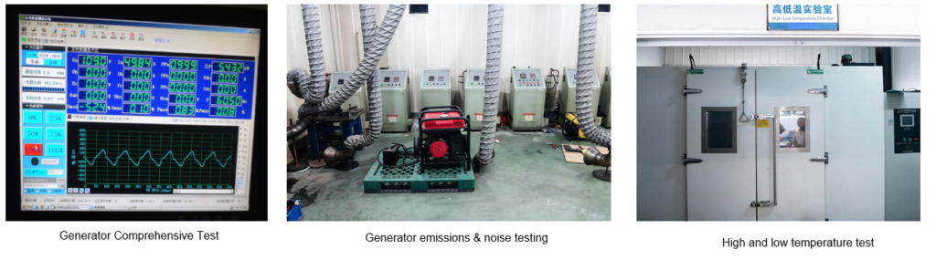
Comprehensive performance, emission and noise, and high- and low-temperature testing for finished NEWTOP generators.
NEWTOP’s finished-generator inspection facilities cover three areas shown in the factory testing images:
Comprehensive Generator Testing
Electrical output and overall operation are observed after final assembly. This helps check whether the engine, alternator, control system, and outlets work together as a complete unit.
Emission and Noise Testing
Emission and operating-noise checks examine characteristics affected by combustion, exhaust design, engine condition, vibration control, and working load.
Alto- and Low-Temperature Testing
Environmental testing checks generator operation under changing temperature conditions. Temperature can influence starting, fuel delivery, lubrificazione, batteries, wiring, and other electrical components.
These checks connect the generator’s technical specifications with the performance of the finished machine. They also provide stronger evidence than relying only on an engine start-up inspection.
Basic Maintenance Keeps the System Working
Every maintenance task protects one part of the energy path.
Fresh gasoline and a clean fuel system help fuel reach the carburetor. A clean air filter supports the correct mixture. The spark plug supports ignition, while suitable engine oil protects the piston, crankshaft, camshaft, and bearings.
Cooling openings should remain clear, and cables, plugs, breakers, and electrical connections should be checked regularly. Backup generators also need periodic starting and inspection so that fuel deterioration, battery discharge, corrosione, or loose connections are found before an outage occurs.
Operate Gasoline Generators Outdoors
Gasoline generator exhaust contains carbon monoxide, a colorless and odorless poisonous gas. Portable generators must never operate inside homes, garages, basements, sheds, or other enclosed areas.
The U.S. Consumer Product Safety Commission advises using portable generators outdoors, at least 20 feet away from homes, with the exhaust directed away from doors, finestre, e prese d'aria.
The generator should also be switched off and allowed to cool before gasoline is added. Connection to a building’s electrical system should use suitable transfer equipment installed according to local electrical requirements.
From Gasoline to Usable Power
So, how does a gasoline generator work from beginning to end?
Gasoline and air enter the engine. The spark plug starts combustion, moving the piston and turning the crankshaft. The crankshaft spins the alternator rotor inside the stator, where electromagnetic induction produces electrical current. The governor and voltage regulator then help the generator respond as the connected load changes.
The engine creates rotation. The alternator creates electricity. The control, cooling, protection, and frame systems help the complete unit deliver that power safely and consistently.
Understanding this relationship makes generator specifications easier to evaluate. Engine displacement shows only part of the machine’s capability. Potenza nominale, alternator construction, voltage regulation, testing, protection systems, and component matching reveal more about how the finished generator will perform in real use.
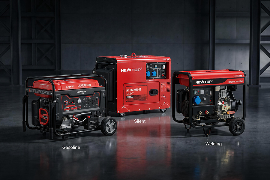
When buyers compare propane vs gasoline generator run time, the number of hours printed on a product page rarely tells the whole story. Runtime changes with the amount of usable fuel, generator load, fuel-specific rated output, tank or cylinder size, ambient temperature, and the way fuel is replenished.
With the same liquid volume and a comparable electrical load, gasoline will generally support a longer run because it contains more energy per gallon. The U.S. Energy Information Administration lists motor gasoline at about 120,214 Btu per gallon and propane at about 91,452 Btu per gallon. A larger propane cylinder or bulk tank, Tuttavia, can provide more total fuel than a generator’s built-in gasoline tank and may therefore keep the generator operating for longer overall.
The useful question is not simply, “Which fuel lasts longer?”
It is:
How long can the generator support the required load with the fuel supply actually available at the site?
Why Published Run-Time Numbers Are Difficult to Compare
A runtime figure only becomes meaningful when the test conditions are clear.
Consider two specifications:
- Generator A: 10 ore di autonomia
- Generator B: 8 ore di autonomia
Generator A appears to perform better. But suppose its figure was recorded at 25% load, while Generator B was tested at 50% load. The longer figure no longer proves better fuel performance because the second generator was producing more electricity during the test.
Fuel quantity creates another problem. A gasoline runtime figure may be based on the generator’s full onboard tank, while the propane figure may use one portable cylinder. Those containers do not necessarily hold comparable amounts of usable energy.
A proper comparison needs answers to five questions:
How much fuel was used?
For gasoline, check the tank capacity in liters or gallons. For propane, check the actual fuel weight or usable liquid capacity of the cylinder.
What load was applied?
Runtime at 25% load cannot be compared directly with runtime at 50% or rated load.
Was output different on each fuel?
Dual-fuel generators may provide different rated and maximum outputs on gasoline and propane. The same appliance load can therefore represent a different percentage of the generator’s capacity on each fuel.
Was economy mode active?
An engine that automatically reduces speed under light demand may consume less fuel than one operating at a fixed speed.
Were the operating conditions similar?
Temperature, elevation, equipment condition, and load changes can all move real-world runtime away from the published figure.
Without these details, an advertised number should be treated as a reference rather than a promise.
Put Both Fuels on the Same Basis
The simplest runtime estimate is:
Estimated runtime in hours = usable fuel quantity ÷ hourly fuel consumption at the expected load
The fuel quantity and consumption rate must use matching units. Pounds of propane cannot be divided directly by a gasoline consumption figure expressed in liters per hour. Similarly, a fuel-consumption value stated in grams per kilowatt-hour needs rated output and fuel mass before it can be translated into operating hours.
The expected load also needs to reflect real use.
A generator supplying steady lighting may consume fuel differently from the same generator powering a refrigerator, compressor, pompa, or construction tool. Motor-driven equipment can draw substantially more power during startup, and repeated starting cycles affect consumption even when average running wattage appears moderate.
Before comparing fuels, buyers should calculate:
- The equipment expected to run at the same time
- Normal running wattage
- Starting or surge demand
- Expected average load during the operating period
- The amount of reserve capacity needed
Using maximum generator output as the normal load figure will produce a misleading runtime estimate. Maximum output is intended for temporary demand, not continuous operation.
Fuel Supply Can Reverse the Result
The higher energy content of gasoline per gallon does not automatically mean that every gasoline setup will run longer. The total fuel supply often decides the practical outcome.
Benzina: A Fixed Onboard Supply
Portable gasoline generators commonly carry their fuel in an integrated tank. This creates a clear, self-contained setup: the generator is transported with its tank, filled before use, and operated until fuel runs low.
The main limitation is fixed capacity. A 15-liter or 25-liter tank cannot be expanded without stopping the generator and refueling it according to the manufacturer’s instructions.
Gasoline condition also affects readiness. Fuel left unused for extended periods can deteriorate, so a generator intended for emergency use needs a fuel rotation and maintenance plan. Long theoretical runtime has little value when old fuel, deposits, or a neglected carburetor prevents dependable startup.
Propane: Runtime Depends on the Connected Supply
Propane is stored as a liquid under pressure and changes into gas as pressure is released for combustion. This makes external cylinders and larger storage tanks possible, giving users more flexibility over the quantity of fuel connected to the generator.
A small portable cylinder may provide less runtime than a full gasoline tank. A larger propane supply may provide considerably more. The comparison changes each time cylinder capacity changes.
Propane delivery also depends on vaporization. Tank size, liquid level, surrounding temperature, umidità, and the tank surface in contact with liquid all affect the rate at which propane can turn into usable vapor. Lower temperatures and lower fuel levels reduce vaporization capacity, while tank frosting can further restrict it.
For a larger generator operating under sustained load, buyers therefore need to check more than total propane quantity. The cylinder and regulator system must also be able to supply fuel at the required rate.
Three Runtime Questions Buyers Actually Ask
Published hour figures become easier to assess when they are connected to a specific operating requirement.
“Can the generator cover one full work shift?”
A contractor planning an eight-hour shift should not begin with the brochure’s longest runtime claim. The calculation should use the expected average site load.
Power tools may run intermittently, while lighting, pompe, charging equipment, or temporary facilities may stay active throughout the day. Motor-starting demand and repeated load changes also need to be included.
The fuel plan should show:
- Expected consumption during the shift
- Fuel remaining at the end of the shift
- Whether refueling or changing cylinders will interrupt work
- How reserve fuel will be transported and stored
- Whether the propane supply can maintain adequate vaporization under the expected temperature and load
A nominal ten-hour runtime at light load may not cover an eight-hour shift once heavier equipment is connected.
“Can it run through an overnight outage?”
Overnight backup is usually less about maximum output and more about maintaining essential loads.
Refrigeration, selected lighting, communication equipment, fans, security systems, and a small water pump may use much less power than the generator’s full rated capacity. Removing non-essential equipment can extend runtime more effectively than increasing fuel storage alone.
Buyers should calculate the likely nighttime load rather than using the total wattage of every appliance on the property. They should also allow a reserve rather than planning to empty the tank or cylinder completely before morning.
For portable generators, overnight operation still requires safe placement, weather protection, exhaust clearance, and regular supervision. Runtime should never be extended by moving the generator into a garage, shed, or other enclosed area.
“Can runtime be extended without buying a larger generator?”
Often, SÌ.
Possible measures include:
- Reducing unnecessary electrical loads
- Avoiding simultaneous startup of high-demand equipment
- Using a larger compatible propane supply
- Scheduling heavy equipment for separate operating periods
- Maintaining the engine, filtro dell'aria, and fuel system
- Selecting a generator whose rated output places the normal load in a more suitable operating range
A larger generator is not automatically more fuel-efficient. If normal demand is low, an oversized unit may add purchase cost and operate outside its most practical load range.
The first step should be improving the load and fuel plan, not simply increasing maximum output.
A Real Gasoline Specification Shows What to Check
A manufacturer’s specification can provide the inputs needed for runtime planning even when it does not state one simplified number of hours.
The NEWTOP NTGR6500H2 gasoline generator, Per esempio, lists:
- 5.5 kW rated output
- 6.0 kW maximum output
- 389 cc, 13 hp OHV engine
- Fuel consumption of no more than 370 g/kWh
- 25-liter fuel tank
- Electric starting
- Copper-wire alternator
- Low-oil and short-circuit protection
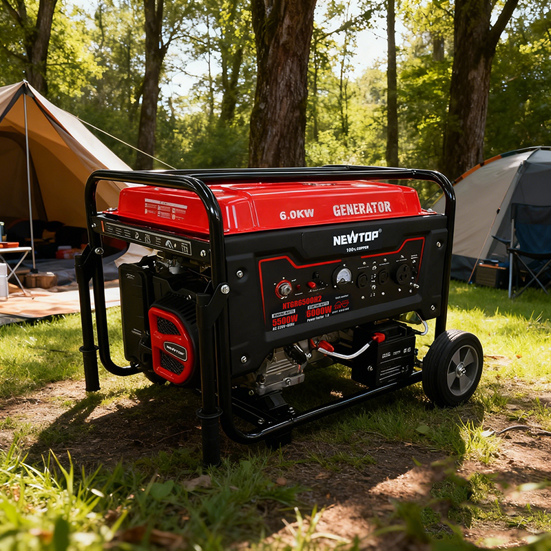
The model also uses a forged crankshaft and camshaft, a full steel frame, and vibration-absorbing mounts for extended outdoor, workshop, costruzione, and backup operation.
These figures are more useful than a vague “long runtime” claim because they allow buyers to examine the relationship among tank capacity, rated output, and fuel consumption.
They still do not justify one fixed runtime prediction.
Actual consumption changes with load, and the published fuel-consumption value must be interpreted using the manufacturer’s test method. Buyers who need a precise operating-hour estimate should request consumption data at several load levels, ad esempio 25%, 50%, 75%, and rated load.
NEWTOP’s gasoline generator range also includes compact 2.8 kW models, mid-range 5.5 kW e 7.8 kW units, and higher-output 10 kW configurations. This range illustrates why runtime cannot be separated from generator size: cilindrata del motore, output demand, capacità del serbatoio, and intended workload change from one power class to another.
Runtime Information to Request from the Supplier
Instead of asking only, “How many hours will it run?”, buyers should request the test information behind the number.
| Information Required | Perché è importante |
|---|---|
| Rated Output on Gasoline | Shows the usable continuous output for the gasoline calculation. |
| Rated Output on Propane | May differ from gasoline output on a dual-fuel generator. |
| Gasoline Tank Capacity | Identifies the fuel quantity behind the gasoline runtime. |
| Propane Cylinder Size and Usable Fuel Amount | Identifies the actual propane supply used in the test. |
| Runtime Test Load | Allows a fair comparison between published runtime figures. |
| Fuel Consumption at Several Loads | Supports more accurate calculations for different applications. |
| Economy-Mode Status | May affect fuel consumption when the generator operates under partial load. |
| Ambient Test Temperature | Provides important context for propane vaporization performance. |
| Starting Loads Used During Testing | Shows whether motor-driven equipment and surge demand were represented. |
| Required Regulator and Connection | Confirms that the propane supply can meet the engine’s fuel demand. |
| Recommended Fuel Reserve | Helps prevent an unexpected shutdown before refueling or cylinder replacement. |
| Refueling or Cylinder-Change Procedure | Reveals whether continuous work will be interrupted. |
A supplier that provides the test basis makes it easier for distributors and end users to set realistic expectations. A single hour figure without fuel quantity and load percentage offers far less value.
Safety Comes Before Additional Runtime
Both gasoline and propane generators produce carbon monoxide. Portable units must operate outdoors and away from occupied buildings, with exhaust directed away from doors, finestre, e prese d'aria. The U.S. Consumer Product Safety Commission advises placing portable generators at least 20 feet from the home whenever possible.
Gasoline should not be added while the generator is running or hot. Propane cylinders, regulators, tubi, and connectors must match the equipment instructions and applicable gas-safety requirements.
A longer hose, improvised fuel connection, indoor placement, or unsafe hot refueling is never an acceptable way to gain more operating time.
What Buyers Should Really Compare
Gasoline contains more energy per gallon than propane, so an equal-volume comparison generally favors gasoline. Real generator installations rarely use equal fuel volumes, Tuttavia. A propane generator connected to a larger external supply may run longer than a gasoline model limited to its onboard tank.
A reliable propane vs gasoline generator run time comparison should place both fuels under the same conditions:
- Comparable electrical load
- Clearly stated rated output
- Known usable fuel quantity
- Matching runtime test conditions
- Suitable tank or cylinder capacity
- Realistic temperature and operating pattern
- Safe refueling or cylinder replacement plan
The most useful runtime figure is not the largest number in a catalog. It is the number of hours the generator can support the required equipment before the available fuel supply must be safely replenished.
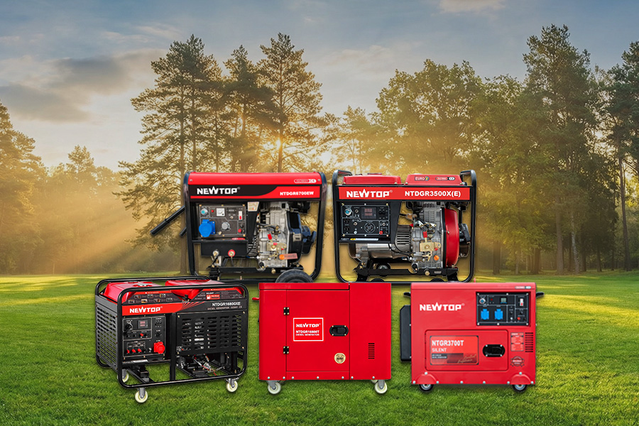
The Diesel Generator vs Gasoline choice mainly depends on running hours, power demand, portability, fuel availability, and budget. Diesel generators are generally better suited to frequent or extended operation, while gasoline generators are often more practical for shorter backup periods and mobile tasks.
Tuttavia, fuel type alone does not decide whether a generator will perform well. Potenza nominale, motor-starting demand, engine construction, fuel tank capacity, maintenance access, and the cost of downtime can be just as important. A correctly sized gasoline generator may serve a small workshop better than an oversized diesel unit, while a diesel generator may offer better long-term value on a site that needs power throughout the working day.
Diesel Generator vs Gasoline: Differenze chiave
Both generator types use an internal combustion engine to drive an alternator and produce electricity. The practical difference lies in how the engine delivers power and how the generator fits the intended workload.
Diesel generators are commonly selected for frequent use, sustained loads, and higher-capacity applications. Compared at a similar output and under extended operation, diesel models may offer more favorable fuel consumption. Their mechanical construction also tends to suit applications where the generator is expected to work regularly.
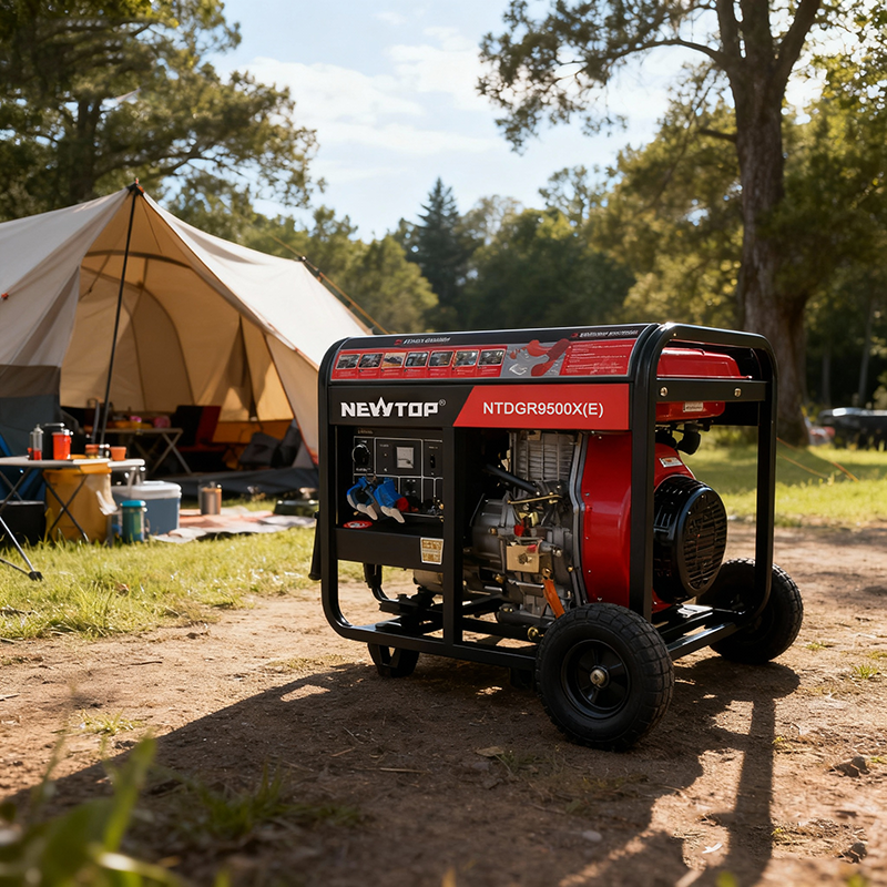
Gasoline generators are widely used where portability, lower initial investment, and intermittent operation matter more. Many compact gasoline models are easier to move between locations and are suitable for temporary work, small businesses, household backup, and outdoor use.
These are general tendencies rather than fixed rules. Actual performance depends on the generator model, cilindrata del motore, load percentage, alternator, enclosure, cooling system, and maintenance condition.
| Decision Factor | Diesel Generator | Gasoline Generator |
|---|---|---|
| Typical Operating Pattern | Frequent or extended operation | Occasional or shorter operation |
| Initial Investment | Usually higher in comparable classes | Often lower in portable power ranges |
| Fuel Use Over Long Periods | Often more favorable at a similar output and sustained load | Can become less economical during extended operation |
| Mobility | Commonly used in fixed, enclosed, or wheeled configurations | Smaller models are often easier to transport |
| Load Suitability | Frequently selected for sustained commercial and jobsite loads | Suitable for moderate loads and temporary work |
| Structure Options | Open-frame and silent enclosed models | Mainly portable open-frame models, with other options depending on the range |
| Applicazioni comuni | Costruzione, fattorie, strutture commerciali, and long backup periods | Small workshops, mobile service, household backup, and short outdoor tasks |
| What Buyers Should Verify | Potenza nominale, consumo di carburante, enclosure, running time, and service access | Potenza nominale, capacità del serbatoio, portability, starting system, and surge output |
Specifications from individual models should always take priority over general fuel-type comparisons. Buyers should compare rated output, maximum output, consumo di carburante, capacità del serbatoio, noise level, and recommended operating conditions before ordering.
Which Generator Is Better for Commercial Use?
Commercial generator selection should begin with the expected duration and frequency of each power interruption.
For a small shop, office, restaurant, or service business that only experiences occasional short outages, a gasoline generator may provide sufficient backup at a more manageable initial cost. It can support selected lighting, communication devices, payment systems, fans, refrigeration, or other essential equipment, provided that the total running and starting loads remain within the generator’s rated capacity.
The priorities change when outages last for several hours or happen several times each week. Fuel consumption becomes more important, and the generator must maintain stable output for longer periods. A diesel generator may then offer a better fit, particularly for warehouses, larger workshops, fattorie, hospitality businesses, and facilities where power loss quickly affects revenue.
Commercial buyers should establish four points before choosing:
✅ Expected running time
Estimate how many hours the generator may operate during a normal outage rather than relying only on annual outage frequency.
✅ Essential electrical loads
Identify which equipment must remain active. Refrigeration systems, pompe, air compressors, and other motor-driven equipment may require substantially more power during startup.
✅ Backup or primary operating role
A generator used only during grid failure has a different duty pattern from one used as a regular power source in an area with limited grid access.
✅ Cost of downtime
For businesses that lose products, capacità produttiva, or customer transactions during an outage, operating reliability may matter more than the lowest purchase price.
Automatic transfer requirements should also be considered for fixed commercial installations. Where uninterrupted changeover is important, generator compatibility with the intended transfer and control system should be confirmed before purchase.
Which Generator Is Better for Construction Sites?
Construction sites place different demands on a generator. Loads change throughout the day, equipment may have high starting current, and the generator often operates around dust, vibration, Calore, and frequent movement.
Diesel generators are commonly chosen for longer shifts and repeated jobsite use. They may be better suited to powering pumps, mixers, welders, compressors, lighting systems, and temporary site facilities over sustained periods. A heavier frame is also less of a disadvantage when the generator remains in a fixed work area or is mounted on a wheeled platform.
Gasoline generators remain practical for smaller crews and shorter assignments. Repair work, finishing tasks, temporary lighting, and mobile tools may only require power for a few hours. In those cases, a compact gasoline generator can be easier to load, unload, and move around the site.
The decision should reflect how the site actually works:
- Long daily shifts with sustained loads: diesel is often the stronger candidate.
- Short tasks across multiple work areas: gasoline may provide easier mobility.
- Tools with electric motors: starting wattage must be checked, not only normal running wattage.
- Dusty or hot conditions: filtration, cooling, frame strength, and maintenance access become more important.
- Noise-sensitive projects: compare enclosed and open-frame models using actual noise specifications.
- Remote sites: choose the fuel that can be supplied, stored, and managed reliably in that location.
Fuel type cannot compensate for poor sizing. An undersized generator may struggle during motor startup or trip under changing loads. An oversized unit adds cost and may operate inefficiently when the average load remains very low.
Which Generator Is Better for Emergency Use?
Emergency use includes several very different situations. A homeowner preparing for a short grid outage does not have the same requirements as a shelter, communication site, flood response team, or large commercial facility.
A gasoline generator is often practical for temporary emergency backup. Portable models can be deployed quickly and may provide enough power for lighting, communication equipment, fans, selected appliances, and small pumps. This makes them useful where ease of movement and lower upfront cost are priorities.
A diesel generator becomes more attractive when emergency power may be required for many hours or several days. Larger facilities and response operations may need more sustained output, longer service capability, or a silent enclosed structure that can remain in a fixed location.
Fuel planning must form part of the emergency plan. Gasoline can deteriorate during prolonged storage, while stored diesel also needs protection from water and contamination. Existing equipment can influence the decision as well. A contractor, farm, or emergency organization that already operates diesel machinery may find diesel storage and refueling easier to integrate.
Generator Safety Cannot Be Treated as Optional
Both diesel and gasoline generators produce carbon monoxide and must never be operated inside homes, garages, basements, sheds, or other enclosed spaces. The U.S. Consumer Product Safety Commission advises operating portable generators outdoors, at least 20 feet away from homes and buildings, with the exhaust directed away from doors, finestre, e prese d'aria.
Electrical connection also requires care. OSHA advises against connecting a portable generator directly to a building’s electrical system unless a suitable transfer switch has been installed by a qualified electrician. Cables should be rated for the expected load, and grounding, bonding, weather protection, and ground-fault protection must follow the generator manufacturer’s instructions and local electrical requirements.
How to Choose the Right Generator Size
The required generator output should be calculated before deciding between diesel and gasoline.
Begin by listing the equipment that may run simultaneously. For each item, record its normal running wattage and, where applicable, its starting demand. Pumps, compressors, refrigerators, and power tools with electric motors may briefly draw several times their normal operating power during startup.
Three figures deserve particular attention:
Continuous Rated Output
This is the power the generator is designed to provide during normal operation. The planned continuous load should remain within this rating rather than relying on maximum output throughout the working period.
Maximum or Surge Output
This temporary capacity helps the generator handle short increases in demand, particularly when motor-driven equipment starts. It should not be treated as the normal operating rating.
Expected Average Load
A generator should have enough reserve capacity to manage load changes without being dramatically larger than necessary. Regular operation at either extremely high or very low load can reduce efficiency and create avoidable operating issues.
For commercial orders, buyers should also confirm:
- Required voltage and frequency
- Single-phase or three-phase output
- Number and type of receptacles
- Electric or recoil starting
- Capacità del serbatoio del carburante
- Tempo di esecuzione continuo
- AVR or voltage regulation requirements
- Open-frame or silent enclosure
- Wheel kits, handles, or lifting requirements
What Generator Construction Changes in Real Use?
Two generators with similar rated output may behave differently once they begin powering tools or equipment. Engine materials, alternator construction, vibration control, protection systems, and frame design all influence long-term use.
NEWTOP offers both gasoline and diesel generator sets, including open-frame and silent configurations. The current range covers multiple output classes, from compact units for outdoor and backup power to higher-capacity diesel models for commercial and construction applications. Selected NEWTOP generators use copper-winding alternators, steel frames, reinforced engine components, and designs intended to operate in temperatures from -10°C to 50°C.
The differences are easier to understand through actual product configurations.
Gasoline Generator Construction
The NEWTOP NTGR6500H2 provides 5.5 kW rated output and 6.0 kW maximum output. Its engine uses a strengthened 42CrMo forged crankshaft and camshaft, while a SENCI copper-wire alternator supports stable voltage and overload performance. A full steel frame with vibration-absorbing mounts protects the machine during demanding work.
The model also includes a 25 L fuel tank, low-oil warning, and short-circuit protection. These features make the generator suitable for construction sites, small workshops, manutenzione della proprietà, and extended household backup where a gasoline model is still preferred.
Open-Frame Diesel Generator Construction
For medium-to-heavy power requirements, the NEWTOP NTDGR6500X(E) combines a forged-steel crankshaft, nitrided gears, Iniezione di carburante con tecnologia BOSCH, and a copper-winding alternator. The anti-vibration steel frame helps protect the engine and alternator during construction, agricolo, and commercial operation.
This model provides 4.8/5.0 kVA rated output and up to 5.2/5.5 kVA maximum output, depending on frequency configuration. The product structure reflects the priorities often associated with diesel equipment: load handling, mechanical strength, and stable output over longer working periods.
Silent High-Power Diesel Construction
Where higher output and lower operating noise are needed together, a silent enclosure may be more appropriate than an open frame. The NEWTOP NTDGR16800T combines 11 kW rated output with a 12 kW maximum output, a 42CrMo forged crankshaft, nitrided gear components and a 100% copper SENCI alternator.
Its enclosed body reduces operating noise while providing additional protection for internal components. The model is designed for construction, backup commerciale, and other demanding applications where both power capacity and operating environment matter.
These examples show why buyers should compare more than fuel type and horsepower. The alternator, crankshaft, gear structure, protection system, frame, and enclosure can determine how well a generator fits the intended market.
Manutenzione, Parti, and Local Technical Support
A well-maintained gasoline generator can perform more reliably than a neglected diesel unit. Engine type does not replace regular inspection and service.
Before operation, users should check:
- Engine oil level and condition
- Fuel quality and storage condition
- Air and fuel filters
- Cooling airflow
- Cable and receptacle condition
- Battery condition on electric-start models
- Telaio, mounts, and fasteners
- Signs of fuel or oil leakage
Backup generators should be started and tested at scheduled intervals. Waiting until an actual power failure to check the generator can leave old fuel, a discharged battery, or an electrical fault undiscovered.
For distributors and commercial buyers, parts support also affects the total ownership experience. Filters, starting components, control panels, voltage regulators, alternator parts, and common engine components should be available without requiring the replacement of the complete generator.
NEWTOP supplies gasoline and diesel generators across multiple power ranges, along with product selection and spare-parts support for wholesale customers. This allows distributors to build a range for households, appaltatori, fattorie, workshops, and commercial backup users rather than relying on one generator type for every application.
Diesel Generator vs Gasoline: Making the Final Decision
Choose a diesel generator when the application involves frequent operation, sustained loads, longer backup periods, or higher-capacity commercial and construction demand. Compare actual fuel consumption, rated output, enclosure, noise, and service access before deciding on a model.
Choose a gasoline generator when portability, lower initial investment, faster deployment, and occasional operation are the main priorities. It is often the more practical option for small businesses, mobile work, temporary construction tasks, and short emergency outages.
The final Diesel Generator vs Gasoline decision should be based on the hours the generator will run, the equipment it must start, the fuel available locally, and the level of downtime the user can accept. Once those requirements are defined, fuel type becomes one part of a much clearer selection process.
The global boating industry continues to evolve with growing demand for reliable gasoline and electric propulsion systems. Whether you’re a boat brand, marine equipment distributor, wholesaler, or OEM buyer, choosing the right outboard motor manufacturer is essential for product quality, long-term business growth, e la soddisfazione del cliente.
In questa guida, we’ve selected 10 reputable outboard motor manufacturers from China, Europe, and North America. They represent different strengths—from cost-effective gasoline engines and OEM & ODM outboard motors to innovative electric propulsion systems—helping you compare potential outboard motor suppliers for your business.
An Overview of Top 10 Outboard Motor Manufacturers
| Produttore | Posizione | Founded | Prodotti principali | Key Strength |
|---|---|---|---|---|
| NEWTOP | Shangai, Cina | 2003 | 2-Motori fuoribordo a corsa, 5–15HP Engines, Eliche & Pezzi di ricambio | 500K+ annual capacity, OEM/ODM, 100+ global distributors |
| Hidea Power Machinery | Hangzhou, Cina | 2003 | Benzina & Electric Outboard Motors | Exported to 80+ countries with an extensive dealer network |
| ePropulsion | Shenzhen, Cina | 2012 | Electric Outboards, Inboards, Batteries & Pod Drives | Leading electric marine propulsion innovator |
| Seanovo Power Machinery | Hangzhou, Cina | — | Gasoline Outboard Motors & Pezzi di ricambio | OEM manufacturing with strong export experience |
| Zhejiang Canglong Power Machinery | Zhejiang, Cina | — | 2-Colpo, 4-Colpo & Electric Outboards | Broad 5HP–40HP product portfolio |
| TEMO | France | 2018 | Portable Electric Outboard Motors | Compact and lightweight propulsion for small boats |
| Suzuki Marine | Hamamatsu, Giappone | 1965 | 4-Motori fuoribordo a corsa & Marine Engines | Global leader in fuel-efficient four-stroke technology |
| Elco Motor Yachts | New York, USA | 1893 | Electric Outboards & Inboards | More than a century of electric marine engineering |
| Flux Marine | Rhode Island, USA | 2018 | High-Performance Electric Outboard Motors | Premium electric propulsion with smart digital controls |
| Yamaha Marine | Iwata, Giappone | 1955 | 2-Colpo & 4-Motori fuoribordo a corsa, High-Power Marine Engines, Eliche | World-leading brand known for reliability, innovation, and global dealer support |
NEWTOP
Raccomandazione: ☆☆☆☆☆
Posizione: Shangai, Cina (Manufacturing Base in Jiaxing, Zhejiang)
Prodotti principali: 2-colpo gasoline outboard motors, 5HP–15HP outboard engines, outboard motor propellers, pezzi di ricambio, OEM & ODM outboard motors
MOQ: Flexible for OEM/ODM orders
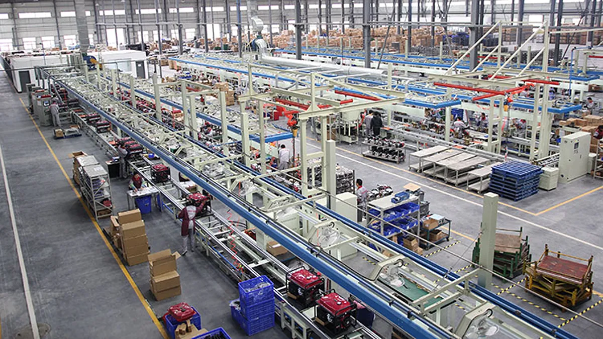
Fondato nel 2003, NEWTOP is a professional China outboard motor manufacturer specializing in outdoor power equipment and reliable small-to-medium horsepower marine engines. Operating from a 10,000㎡ 6S-managed manufacturing facility, the company has an annual production capacity of over 500,000 units and has earned 26+ international certifications, including CE, ISO, and EU Stage V (Euro 5) compliance for selected models. Its product portfolio includes durable 2-stroke gasoline outboards, outboard motor propellers, and replacement parts for fishing boats, gommoni, barche in alluminio, and other recreational vessels.
As an export-oriented outboard motor factory, NEWTOP provides flexible OEM & ODM solutions for global importers, private-label brands, and outboard motor distributors. Oggi, the company works with 100+ distributori worldwide, while customers in many African and Latin American markets can purchase NEWTOP products directly through local dealers and retail stores. Backed by stable manufacturing quality, responsive technical support, and an expanding global service network, NEWTOP has become a trusted outboard engine manufacturer and long-term outboard motor supplier for partners seeking dependable marine propulsion solutions.
Hidea Power Machinery

Posizione: Hangzhou, Zhejiang, Cina
Prodotti principali: Gasoline outboard motors, electric outboard motors, marine engine parts, outboard accessories
MOQ: Contact for quotation
Hidea Power Machinery is one of China’s best-known outboard motor manufacturers, offering both gasoline and electric propulsion solutions. With an international distribution network spanning more than 80 paesi e regioni, Hidea has established itself as a trusted outboard motor supplier for dealers and marine equipment distributors worldwide. Its product portfolio covers multiple horsepower ranges suitable for leisure boats, barche da pesca, and commercial applications.
The company continuously invests in manufacturing technology, quality control, and product development to improve engine efficiency and durability. Besides complete engines, Hidea also supplies various spare parts and accessories, enabling outboard motor distributors to build comprehensive product offerings for their local markets.
ePropulsion

Raccomandazione: ☆☆☆☆
Posizione: Shenzhen, Guangdong, Cina
Prodotti principali: Electric outboard motors, inboard motors, Pod Drive systems, marine batteries, hybrid propulsion systems
MOQ: Contact for quotation
Fondato nel 2012, ePropulsion has become one of the world’s leading electric outboard engine manufacturers, focusing exclusively on sustainable marine propulsion. Its product lineup includes electric outboards, inboard systems, pod drives, intelligent battery systems, and integrated marine control technologies designed for recreational and commercial vessels.
The company is recognized for combining innovative engineering with quiet operation, zero emissions, and low maintenance requirements. For buyers seeking environmentally friendly alternatives to conventional gasoline engines, ePropulsion offers advanced propulsion systems supported by an expanding international dealer network and continuous product innovation.
Seanovo Power Machinery

Raccomandazione: ☆☆☆☆
Posizione: Hangzhou, Zhejiang, Cina
Prodotti principali: Gasoline outboard motors, marine engines, outboard spare parts
MOQ: Contact for quotation
Seanovo Power Machinery is a professional outboard motor factory dedicated to manufacturing gasoline-powered marine engines and related accessories. Located in Hangzhou, the company serves international distributors, grossisti, and OEM customers with a broad range of portable outboard motors suitable for fishing boats, gommoni, and recreational watercraft.
With specialized production lines and export experience, Seanovo focuses on stable manufacturing quality and competitive pricing. In addition to complete engines, it supplies replacement components that help customers maintain reliable after-sales support. Its manufacturing flexibility also makes it a practical choice for buyers looking for customized branding opportunities.
Zhejiang Canglong Power Machinery

Raccomandazione: ☆☆☆☆
Posizione: Zhejiang, Cina
Prodotti principali: 2-stroke gasoline outboard motors, 4-motori fuoribordo a corsa, electric outboard motors, 5HP–40HP engines
MOQ: Contact for quotation
Zhejiang Canglong Power Machinery manufactures both gasoline and electric outboard motors, covering horsepower ranges from approximately 5HP to 40HP. Through its Laogen brand, the company offers several product series designed to balance durability, efficienza, and affordability for recreational boating markets.
Its diverse product portfolio enables distributors to serve customers with varying performance requirements while maintaining competitive pricing. As a growing outboard motor supplier, Canglong continues expanding its export business and provides practical solutions for dealers seeking mid-range marine propulsion products.
TEMO

Raccomandazione: ☆☆☆☆
Posizione: Nantes, France
Prodotti principali: Portable electric outboard motors, TEMO.450 electric propulsion system
MOQ: Contact for quotation
Fondato nel 2018, TEMO is a French manufacturer of portable electric boat motors. The company develops lightweight, easy-to-install electric propulsion products for tenders, gommoni, sailboats, rowboats, and other light watercraft. Its well-known TEMO.450 model was designed as a compact electric outboard motor for auxiliary propulsion and short-distance marine use.
TEMO has also received France-origin certification for its TEMO.450 and TEMO.1000 outboard models, reinforcing its positioning around French-made electric marine equipment. For distributors targeting the small-boat market, the brand offers a clear example of product-led positioning: simple installation, portability, basso rumore, and easy handling. It is especially relevant to retailers and marine dealers focused on electric outboard motors rather than conventional gasoline engines.
Suzuki Marine

Raccomandazione: ☆☆☆☆☆
Posizione: Hamamatsu, Shizuoka, Giappone
Prodotti principali: 4-motori fuoribordo a corsa, portable outboard engines, high-horsepower marine engines, marine accessories
MOQ: Contact for local distributor
Fondato nel 1965, Suzuki Marine is the marine division of Suzuki Motor Corporation and one of the world’s leading outboard motor manufacturers. The company is best known for its advanced 4-stroke technology, offering outboard engines that deliver excellent fuel efficiency, low emissions, and dependable performance. Its product lineup ranges from compact portable models to high-horsepower engines used on fishing boats, leisure boats, and commercial vessels worldwide.
With decades of engineering expertise and a global dealer network, Suzuki Marine has built a strong reputation for product reliability and innovation. The company continues to invest in cleaner marine technologies and advanced fuel injection systems while providing comprehensive after-sales support through authorized outboard motor distributors. For buyers seeking premium-quality marine engines backed by a globally recognized brand, Suzuki Marine remains a trusted outboard engine manufacturer.
Elco Motor Yachts

Raccomandazione: ☆☆☆☆
Posizione: Athens, New York, USA
Prodotti principali: Electric outboard motors, electric inboard motors, marine propulsion systems
MOQ: Contact for quotation
Elco Motor Yachts is one of the oldest names in electric marine propulsion, with a history dating back more than a century. Oggi, the company manufactures electric motori fuoribordo and inboard propulsion systems serving recreational boat owners and commercial marine applications.
Its long-standing engineering heritage, combined with modern electric technologies, allows Elco to position itself as a premium provider of sustainable propulsion solutions. Buyers looking for established American brands often consider Elco for projects requiring reliable electric propulsion backed by extensive industry experience.
Flux Marine

Raccomandazione: ☆☆☆☆
Posizione: Bristol, Rhode Island, USA
Prodotti principali: High-performance electric outboard motors, battery systems, digital control systems
MOQ: Contact for quotation
Flux Marine focuses on developing high-performance electric outboard engines for recreational boats seeking faster acceleration and advanced digital control. The company integrates proprietary battery technology with intelligent monitoring systems to optimize performance, efficienza, and user experience.
Rather than competing solely on sustainability, Flux Marine positions itself around premium performance and smart technology. Its products demonstrate how electric propulsion can satisfy boaters who expect both environmental benefits and exciting on-water performance.
Yamaha Marine

Raccomandazione: ☆☆☆☆☆
Posizione: Iwata, Shizuoka, Giappone
Prodotti principali: 2-stroke and 4-stroke outboard motors, high-horsepower outboard engines, marine accessories, propellers
MOQ: Contact for local distributor
Fondato nel 1955, Yamaha Marine is one of the world’s most respected outboard motor manufacturers, offering a comprehensive range of outboard engines for recreational boating, commercial fishing, and professional marine applications. Its portfolio spans from lightweight portable models to high-horsepower V6 and V8 outboards, all engineered for outstanding reliability, efficienza del carburante, and smooth performance in demanding environments.
Backed by decades of engineering innovation and an extensive global dealer network, Yamaha Marine has earned a reputation for premium quality and dependable after-sales support. The company continues to invest in advanced fuel injection technologies, digital control systems, and high-performance marine engineering, making it a preferred outboard motor supplier for boat builders, marine dealers, and outboard motor distributors worldwide.
How to Choose a Reliable Outboard Motor Manufacturer?
Choosing an outboard motor manufacturer should involve more than comparing horsepower and unit price. Importatori, boat builders, and marine distributors should assess whether the supplier can provide consistent quality, technical support, parts availability, and a product range that matches their regional customers.
- Confirm manufacturing capability: Ask whether the company operates its own outboard motor factory, engineering team, quality-control process, and test procedures.
- Review power range and fuel type: Select gasoline, elettrico, 2-colpo, 4-colpo, or hybrid products based on boat type, local regulations, buyer preferences, and expected operating conditions.
- Check OEM and ODM support: For private-label programs, confirm branding options, confezione, manuali, product modifications, and sampling procedures for OEM & ODM outboard motors.
- Verify compliance documentation: Request applicable certifications, test reports, shipping documents, safety information, and market-specific compliance support.
- Evaluate parts supply: Reliable access to outboard motor propellers, impellers, candele, fuel-system components, and repair parts is essential for distributor retention.
- Assess after-sales capability: Ask about warranty policy, technical manuals, troubleshooting guidance, training resources, and response times for dealer claims.
- Clarify commercial terms: Confirm MOQ, lead time, payment terms, container loading plans, spare-parts packages, and territory or distributor policy before ordering.
Considerazioni finali
The right outboard motor supplier depends on your market position, target boat category, power requirements, and service capacity. Gasoline outboard engines remain important for many fishing and recreational applications, while electric outboard motors create new opportunities in lightweight boats, low-noise waterways, and sustainability-driven markets.
For buyers seeking compact gasoline outboard motors, private-label flexibility, pezzi di ricambio, and an experienced China-based manufacturing partner, NEWTOP provides a practical starting point. Its broader outdoor power equipment capabilities can also help distributors consolidate sourcing across complementary product categories.
If you’re planning your next sourcing project, contact NEWTOP to discuss customized solutions for your market.
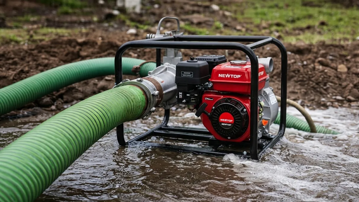
When selecting a water pump for construction, agricoltura, drenaggio, or industrial applications, choosing the correct pump type is critical. Two of the most common options are trash pumps and clean water pumps. Although both are designed to move water, they are built for very different working conditions.
A clean water pump is designed for transferring relatively clear water with minimal particles, while a trash pump is engineered to handle muddy water, wastewater, and liquids containing solid debris. Choosing the wrong pump can lead to reduced performance, frequent blockages, higher maintenance costs, or even pump damage.
In questa guida, we will explain the difference between trash water pumps and clean pompe dell'acqua, including their working principles, liquid handling ability, prestazione, applicazioni, and how to select the right solution for your market.
What Is a Trash Pump?
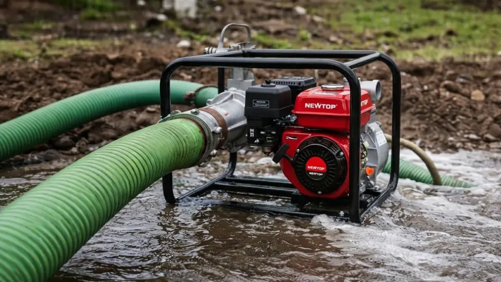
A trash pump is a heavy-duty centrifugal pump built to aggressively move dirty water loaded with sludge, sabbia, and debris without clogging or failing.
Core Definition and Purpose
Engineers specifically build trash pumps to move dirty water packed with solid particles like sludge, sabbia, sporco, and leaves. This contrasts directly with standard clean-water pumps, which operators intend only for clear liquids. If you expose a clean-water pump to heavy contamination, you risk immediate blockage or catastrophic seal failure. The industry categorizes trash pumps as dirty-water pumps because they operate effectively in demanding environments where liquids mix heavily with solid waste.
Key Design Characteristics
The ability to process solid waste requires a specific mechanical architecture. Manufacturers construct these pumps with reinforced components to survive constant internal abrasion.
- Large internal clearances: The design allows suspended solids and debris to pass straight through without plugging internal passages.
- Heavy-duty construction: Production relies on abrasion-resistant materials to withstand the mechanical impact and wear caused by sand and grit.
- Specialized impellers: Open or semi-open impellers and specialized volute geometry prevent organic matter, fibers, or plastics from accumulating inside the housing.
Typical Applications and Environments
You deploy a trash pump when the liquid you need to move would destroy a standard transfer pump. Field operators rely on these units across several heavy-duty sectors.
- Flood control: Dewatering inundated basements, garages, and muddy work areas after severe weather or pipe breaks.
- Construction and civil engineering: Draining excavations, utility trenches, and sediment basins filled with groundwater and soil.
- Wastewater and drainage: Clearing sewers, sumps, and drainage channels where organic waste accumulation is common.
- Industrial residue management: Moving process effluents, abrasive slurries, and high-solids streams inside treatment plants.
What Is a Clean Water Pump?
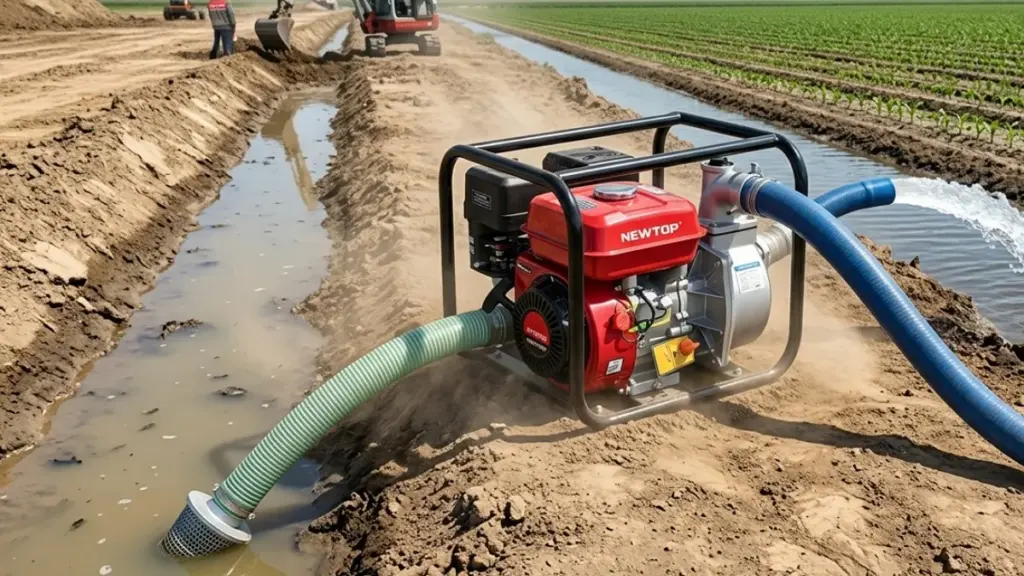
A clean water pump moves clear, solid-free liquids efficiently. It trades debris tolerance for high pressure, making it the standard choice for domestic supply and irrigation.
Definition and Core Function
Clean water pumps are engineered exclusively for clear or potable fluids. Unlike trash pumps built to chew through heavy sludge and debris, these units handle water containing little to no suspended solids.
Engineers restrict the passage size in these pumps to a strict maximum of 5 A 6 millimeters. Manufacturers rate many standard models for absolute zero solid tolerance. They serve as the dedicated clear-liquid alternative when contamination risks are low and performance demands are high.
Hydraulic Design and Efficiency
The internal architecture of a clean water pump prioritizes performance over debris handling. These units utilize narrow flow passages to maximize discharge pressure and hydraulic efficiency. Tighter internal clearances allow them to push water faster and further than dirty-water pumps equipped with identical motor sizes.
Because they operate in non-abrasive environments free of rocks and sand, heavy cast-iron wear plates are unnecessary. Invece, manufacturers construct the housings and impellers from materials suited for clean environments.
- Plastics: Lightweight and highly resistant to chemical corrosion.
- Acciaio inossidabile: Prevents rust in potable water and food-grade applications.
- Coated Metals: Protects internal components during continuous domestic or agricultural use.
Submersible vs. Surface Configurations
Operators deploy these pumps in two primary formats based on the layout of the water source.
- Submersible Units: These operate entirely underwater with hermetically sealed motors. They often utilize integrated float switches that cut the power when water levels drop, preventing dry-running and subsequent motor burnout.
- Surface Models: These sit permanently outside the water source. They connect to the fluid via rigid suction hoses and are standard for shallow well extraction and domestic pressure systems.
Typical Applications
Industry professionals and homeowners deploy clean water pumps for specific, low-debris tasks where pressure and flow rate matter most.
- Domestic Supply: Extracting household drinking water and boosting pressure across residential plumbing systems.
- Agricoltura: Irrigating gardens, frutteti, and small crops directly from clean wells or filtered holding tanks.
- Drenaggio: Evacuating clean or lightly dirty water from flooded basements, swimming pools, and rainwater cisterns.
Maximize Margins With Reliable Garden Machinery

How Does a Trash Pump Work?
Trash pumps use a semi-open impeller and centrifugal force to move heavy debris, relying on retained fluid inside the casing to self-prime automatically.
Centrifugal Pumping Mechanism
A trash pump operates as a heavy-duty centrifugal unit. Water enters the suction port and strikes a high-speed, semi-open impeller positioned inside a spiral-shaped volute casing.
As the impeller spins, it generates centrifugal force that throws the incoming fluid outward against the casing walls. The volute catches this fluid and converts its kinetic energy into a stable pressure head. This pressure physically drives the water out through the discharge port to create a continuous flow.
Self-Priming Operation
Standard centrifugal pumps fail if air enters the suction line. A trash pump solves this problem by retaining a small charge of water inside its casing between active operating cycles.
When the pump engine starts, the impeller spins this retained water to create a partial vacuum. This vacuum draws air up from the suction line. The internal mechanics separate the air from the liquid and expel it through the discharge side. Water then fills the casing, completing the priming process and allowing normal fluid transfer to begin.
Solids and Debris Handling
The defining feature of a trash pump is its ability to process contaminated water without jamming. The unit utilizes a semi-open impeller paired with exceptionally wide flow passages to protect internal components from large particles.
This specialized internal geometry provides specific material handling capabilities:
- Debris Tolerance: Passes solid materials like sand, mud, and sticks up to 3 pollici di diametro.
- Suspended Solids: Pumps fluids containing up to 30% suspended solids by weight.
- Equipment Limits: Requires an upgrade to a specialized heavy-duty slurry pump if solids exceed the 30% threshold.
How Does a Clean Water Pump Work?
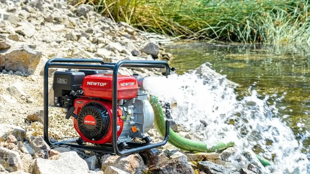
A clean water pump uses a spinning impeller and centrifugal force to convert kinetic energy into stable, usable water pressure for plumbing and irrigation networks.
Water Intake and Impeller Action
The process starts when clear liquid enters the pump chamber through the inlet port. Inside the housing, a motor-driven impeller spins rapidly to accelerate the fluid. As the impeller turns, it generates strong centrifugal force. This physical action pushes the water outward toward the outer edges of the pump body, creating the initial momentum needed for transfer.
Velocity to Pressure Conversion
Speed alone will not push fluid through a complex plumbing layout. The internal pump housing captures the fast-moving water right as it leaves the impeller. Engineers design this casing specifically to translate that kinetic energy into usable discharge pressure. The highly pressurized water then exits the discharge pipe to supply the connected piping network.
Automatic Operation in Well Systems
Household setups rely on additional components to run the pump automatically and efficiently. The system utilizes three primary mechanisms:
- Pressure tank: Stores pressurized water to maintain consistent delivery and reduce short-cycling on the motor.
- Pressure switch: Activates the motor the exact moment line pressure drops from an open fixture.
- Check valve: Stops water from flowing backward down the well, keeping the system primed and holding line pressure steady.
Performance Variables and Limits
Real-world conditions dictate how effectively a clean water pump runs. The motor must generate enough raw force to overcome gravity, internal pipe friction, e sollevamento verticale. Surface models often require manual priming, meaning operators must fill the casing with water before starting the motor to ensure proper suction. Operators must monitor the fluid source constantly. Operating the pump without water causes dry running, which leads directly to severe friction damage and catastrophic seal failure.
Trash Pump vs Clean Water Pump: Differenze chiave in breve
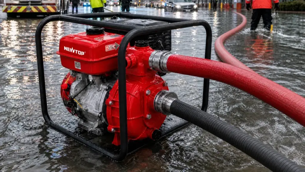
Trash pumps prioritize rugged solids handling in harsh environments, while clean water pumps focus on maximizing hydraulic efficiency and pressure for clear liquids.
| Comparison | Trash Pump | Clean Water Pump |
|---|---|---|
| Water type | Dirty water, muddy water, wastewater | Clear water |
| Solid handling | Handles sand, foglie, and small debris | Limited solid particle handling |
| Impeller design | Open or semi-open impeller design | Closed impeller design |
| Passage size | Larger clearance for solid particles | Smaller clearance for improved efficiency |
| Efficienza | Slightly lower due to heavy-duty construction | Higher efficiency when pumping clean water |
| Manutenzione | Requires inspection and cleaning after dirty water operation | Lower maintenance under proper operating conditions |
| Typical use | Construction sites, flood control, drainage applications | Irrigation, water transfer, approvvigionamento idrico domestico |
| Durabilità | Designed for harsh environments and demanding applications | Designed for cleaner water applications |
Solids Handling and Operating Environment
Trash pumps actively move mud, sabbia, foglie, and solids up to 2–3 inches in diameter without stalling. Operators rely on them as the primary tool for dewatering construction sites, managing municipal wastewater, or clearing sludge pits. They maintain steady flow rates even when the water source is heavily contaminated with abrasive debris.
Clean water pumps strictly handle clear, filtered liquids. They serve domestic water supply systems, pressure boosting stations, and agricultural irrigation networks. If leaves, gravel, or thick mud enters a clean water system, the pump suffers immediate impeller damage and rapid seal failure.
Performance and Efficiency Trade-Offs
Trash pumps prioritize high flow volume and continuous clog resistance over maximum pressure output. The wider internal clearances in trash pumps slightly reduce overall energy efficiency. You trade precise hydraulic performance for the guarantee of reliable operation in unpredictable, dirty conditions.
Clean water pumps deliver superior pressure and hydraulic efficiency when transporting clear liquids over long distances. Their narrow internal passages convert more motor energy into usable head pressure. They excel at pushing water uphill or feeding long sprinkler lines, provided the water remains pristine.
Internal Design and Material Construction
Manufacturers engineer these two pump categories with distinctly different internal architectures to survive their target environments.
- Impeller and Volute: Trash pump models feature thick, cast-iron semi-open impellers and wide volutes designed to absorb repeated impacts from rocks and gravel. Clean water units utilize standard, closed impellers with tight internal clearances optimized solely for clear liquids.
- Mechanical Seals: Trash pumps rely on abrasive-resistant silicon carbide seals to withstand continuous grit. Clean water pumps use standard carbon ceramic seals tailored for non-abrasive environments.
- Maintenance Access: Trash pumps often include quick-release clean-out ports to remove large lodged objects. Clean water pumps lack these ports because they are not meant to ingest large solids.
Cost and Lifecycle Economics
Trash pumps command a higher initial purchase price due to their reinforced, heavy-duty manufacturing materials. The robust cast-iron casings and upgraded sealing systems add upfront expense but drastically reduce downtime in harsh site conditions.
Clean water pumps offer the best long-term value and lowest operating costs only when applied strictly to clear-water applications. Deploying a clean water pump in muddy environments causes rapid mechanical failure. Replacing burnt motors, shattered impellers, and compromised seals makes the standard pump the most expensive choice for heavy-duty tasks.
Which Liquids Can Each Pump Handle?
Match the pump to the liquid. Clear water requires efficient clean water pumps, while turbid fluids demand the larger passages of semi-trash or trash pumps to prevent failure.
Clean Water Pumps for Clear Liquids
Clean water pumps are built exclusively for fluids with almost zero solids. You will use these primarily for potable water, clean rainwater, and lightly treated process water.
Engineers design these pumps with narrow internal passages. This geometry maximizes hydraulic efficiency but leaves the pump highly vulnerable to abrasion and clogging if solids enter the system. Exposure to visible turbidity, sabbia, grit, or fibrous debris causes rapid impeller wear and risks severe motor overload. If the water looks dirty, keep this pump out of it.
Trash Pumps for Heavy Debris and Sludge
When the fluid contains heavy debris, you need a trash pump. Manufacturers engineer these units specifically for dirty liquids, including muddy water, thick slurry, agricultural waste, and heavy flood runoff.
Trash pumps feature open or semi-open impellers capable of passing large solids, often up to two inches in diameter. They handle coarse sediments, gravel, foglie, and twigs without sustaining internal damage or restricting the flow path. You trade some hydraulic efficiency for unmatched reliability in harsh environments.
Semi-Trash Pumps for Intermediate Turbidity
Semi-trash pumps bridge the gap between clean water and heavy-duty trash handling. They manage turbid water containing moderate solids and impurities where a clean water pump would quickly fail.
These units pass small particles ranging from 0.5 A 1 inch in diameter. They are a practical choice for light construction dewatering, landscaping projects, and dirty pond drainage. They offer far better clog resistance than standard pumps but lack the internal capacity to move large rocks or dense, fibrous sludge.
Practical Guidelines for Liquid Assessment
Pump selection starts with a rigorous fluid analysis. Visually inspect the water clarity and estimate the maximum particle size before finalizing your equipment choice. A quick field assessment prevents costly downtime later.
Prioritize clean water pumps when transferring visibly clear fluids where maximum hydraulic efficiency is required. Conversely, select a full trash pump for high-concentration abrasive or fibrous environments. This guarantees continuous reliability and prevents sudden equipment failure when pumping conditions deteriorate.
How Do Performance, Efficienza, and Maintenance Compare?
Clean water pumps prioritize hydraulic efficiency and pressure for clear fluids, while trash pumps sacrifice peak efficiency to maintain continuous high-volume flow in debris-heavy conditions.
Performance Differences in Flow, Pressione, and Solids Handling
Clean water pumps are engineered to maximize pressure (Testa) and move clear liquids rapidly. They use smaller outlets and tighter internal geometries to push water over long distances or uphill. Trash pumps approach performance from the opposite angle. They emphasize raw flow volume over pressure, frequently moving more than 1,000 gallons per minute to evacuate flooded areas or clear large trenches.
The defining operational limit for both pump types is their handling capacity for physical debris:
- Clean water pumps: Possess near-zero tolerance for debris. Even small suspended particles can damage internal components.
- Trash pumps: Utilize specialized impellers and wide volutes to pass solids ranging from 0.5 to over 2 inches without clogging.
Hydraulic Efficiency vs. Operational Efficiency
A standard comparison of peak hydraulic efficiency always favors clean water models. Their tighter internal clearances convert more input energy directly into fluid pressure when operating in pristine water. Trash pumps inherently run with lower hydraulic efficiency. Their larger internal passages create fluid turbulence and recirculation, which requires more power to move the same volume of water.
But in the field, operational efficiency matters more than lab ratings. When you introduce debris into the mix, a clean water pump suffers rapid efficiency loss due to blockages and component wear. A trash pump provides the best practical efficiency by simply staying online and maintaining continuous flow in harsh, contaminated environments.
Maintenance Demands, Wear Resistance, and Uptime
Maintenance profiles differ entirely based on the operating environment. A clean water pump requires very little routine upkeep. If you keep the fluid clean, you mostly just monitor basic lubrication and perform periodic seal inspections. Trash pumps demand a far more active maintenance schedule because they operate in highly abrasive conditions.
Standard maintenance tasks for a trash pump include:
- Strainer cleaning: Frequent clearing of intake screens to prevent large blockages.
- Impeller inspection: Checking the vanes for wear and impact damage from rocks and debris.
- Volute checks: Monitoring the pump casing for internal erosion caused by sand and grit.
Despite these higher scheduled maintenance requirements, trash pumps are built with thicker, heavy-duty materials. This robust construction absorbs the physical punishment of dirty water, drastically reducing unexpected downtime and catastrophic failures when field conditions get tough.
What Are the Best Applications for Each Pump Type?
Match the pump to the fluid. Trash pumps handle high-volume debris removal, while clean water pumps deliver high-pressure transfer for clear liquids.
Ideal Uses for Trash Pumps (Solids and Contaminated Water)
Trash pumps operate in hostile environments where suspended solids would instantly destroy standard impellers. They sacrifice maximum pressure to maintain continuous operation when ingesting heavy debris.
- Flood control and emergency dewatering: Rapidly clearing out basements, garages, and muddy outdoor areas after heavy rainfall.
- Heavy-duty site operations: Supporting construction, civil works, and industrial processes that involve sand, cement, or thick sludge.
- Agricultural and waste management: Emptying dirty ponds, artificial lakes, or agricultural wastewater systems packed with organic matter.
- Performance priority: Delivering high flow rates (≥100 L/min) using robust, semi-open impellers rather than generating high pressure.
Best Scenarios for Clean Water Pumps (Clear Water and Pressure)
When the fluid source is free of sediment, clean water pumps take the lead. Their tight internal clearances allow them to efficiently push fluid further distances and up steeper elevations.
- Domestic water supply: Providing stable pressure boosting from deep wells, cisterns, or holding tanks to residential buildings.
- Targeted irrigation: Powering garden sprinkler systems and light agricultural watering networks using filtered rainwater.
- Clear liquid transfer: Draining or moving water seamlessly across pools, closed reservoirs, and sensitive aquaculture setups.
- Performance priority: Maintaining medium flow rates combined with higher pressure (Testa) for stable, continuous delivery.
Mixed-Use Applications and Dual-Purpose Pumps
Job site conditions often shift. Manufacturers design dual-purpose submersible pumps specifically for environments where water quality fluctuates between clear and sediment-heavy throughout the day.
These hybrid units feature adjustable intake mechanisms that let operators manually switch between clean and dirty water modes. This engineering maximizes energy efficiency during clear water extraction while actively preventing clogs the moment debris enters the basin.
Actionable Checklist: Matching the Pump to Your Task
Avoid premature equipment failure by running through a basic site assessment before deployment. Deploying the wrong pump type guarantees downtime and drives up maintenance costs.
- Assess water composition: Select trash pumps for environments containing sand, foglie, or mud. Use clean water pumps exclusively for clear fluids.
- Define the objective: Choose high-volume submersible pumps for rapid emptying tasks, or pressure-focused pumps for long-distance irrigation.
- Calculate capacity requirements: Verify the necessary flow rate (l/min) and total head height dictated by your specific site layout.
- Ensure appropriate automation and safety: Install float switches for hands-free flood management and dry-run protection to save well pumps from burning out.
How to Choose the Right Water Pump for Your Market
Your pump selection comes down to water quality and pressure needs. Match solids-handling capacity to your jobsite to prevent equipment failure and eliminate costly downtime.
Assess Water Quality and Debris Size
The first step in pump selection is diagnosing the water source. Water quality directly dictates the internal clearances and impeller design your equipment needs to survive.
- Clean water pumps: Handle clear fluids with minimal suspended solids, typically maxing out at 0.25 pollici.
- Trash pumps: Process dirty water containing sediment, foglie, and mud, passing heavy solids between 1.25 E 2 pollici di diametro.
Always select a pump rating that exceeds the largest expected debris size in the fluid. This safety margin prevents immediate clogging and internal damage when site conditions unexpectedly worsen.
Determine Pressure and Flow Requirements
Beyond water quality, you must define the hydraulic demands of the job. Different pump architectures serve entirely different transfer objectives.
- High pressure: Clean water pumps deliver higher discharge pressure, making them the standard for moving fluid over long distances or feeding smaller hoses.
- High volume: Trash pumps trade maximum line pressure for high flow volume, prioritizing rapid dewatering to clear flooded areas fast.
- Port sizing: Trash pumps utilize larger 2-inch to 6-inch ports to ensure debris-laden water moves through the system without restriction.
Match Pump Specifications to Jobsite Applications
You need to align the pump’s design with the actual work environment. Standard centrifugal pumps fail rapidly when misapplied on the jobsite.
- Clean water tasks: Deploy these units for pool draining, basement dewatering after clean floods, and clear-source agricultural irrigation.
- Dirty water tasks: Use trash pumps for construction site dewatering, clearing flooded trenches, and agricultural transfer involving organic matter.
- Dust suppression: Choose a trash pump for jobsite dust control to guarantee reliable operation when drawing from turbid or muddy water sources.
Weigh Upfront Costs Against Potential Downtime
Purchasing decisions often focus on initial price tags, but total lifecycle costs dictate true profitability. Clean water pumps provide a lower purchase price and higher operational efficiency in clear-water environments.
Running a standard clean water pump in muddy conditions is an expensive mistake. The narrow internal clearances will clog rapidly, risking severe equipment damage and expensive project delays.
Trash pumps require a higher initial investment. They offset this cost by featuring reinforced impellers, heavy-duty mechanical seals, and wider internal passages. This rugged construction eliminates costly downtime and keeps your operation running under harsh conditions.
Common Mistakes When Selecting Water Pumps
Selecting the wrong water pump leads to premature failure and inflated operating costs. Match the pump’s hydraulic limits and solids rating to your specific fluid environment to guarantee reliability.
Confusing Pump Types and Fluid Requirements
Buyers frequently grab a standard clean water pump for muddy or debris-filled pits. The narrow passages instantly clog, leading to rapid impeller wear and burned-out motors. On the flip side, deploying a high-flow trash pump for a job requiring high-pressure clean water results in poor performance and wasted fuel. You must correctly match the pump hardware to the exact fluid profile.
- Solids handling limits: Misjudging the maximum solids size and feeding large debris into a pump rated for clear water.
- Fluid chemistry errors: Using standard household pumps in corrosive seawater or chemical fluids without proper material resistance.
- Application mismatch: Relying on a low-pressure trash pump when a dedicated centrifugal or multistage pump is required for high-head transfer.
Incorrect Sizing for Flow, Testa, and Power
Guessing flow and head requirements destroys pump efficiency. Oversizing a pump “just to be safe” forces the unit to operate far from its Best Efficiency Point (BEP). This drastically increases energy consumption and mechanical wear. Conversely, an undersized pump runs continuously at maximum capacity, resulting in chronic motor overloading.
- Friction losses: Underestimating Total Dynamic Head (TDH) by calculating only vertical lift and ignoring friction in hoses, pipes, and fittings.
- Suction limits: Attempting to draw water beyond the physical suction lift limits of surface pumps (tipicamente 7 A 9 metri), causing severe cavitation.
- Volume deficits: Undersizing the flow capacity, leading to inadequate volume delivery and overheating.
Ignoring Material Compatibility and Duty Cycles
You cannot run light-duty domestic equipment on a heavy construction site. Specifying standard materials for highly abrasive environments accelerates wear on critical components like impellers, wear rings, and volute casings. Industrial environments demand equipment rated for exact site conditions.
- Abrasive destruction: Selecting standard cast iron or plastics that erode quickly when pumping sand or grit.
- Duty cycle abuse: Using intermittent-duty domestic pumps for continuous heavy-duty dewatering tasks.
- Short cycling: Failing to size the control system correctly causes excessive on/off cycles, stressing motor starters and wearing out mechanical seals.
Overlooking System Design and Electrical Needs
A pump is only as good as the system surrounding it. Many operators design pipework diameters and layout before selecting the pump. This creates high friction losses and chokes performance. Poor suction layouts—such as using overly long, restrictive hoses or placing intakes directly in bottom sediment—force the pump to work harder than necessary.
- Restrictive layouts: Creating poor suction configurations that starve the pump of water and trigger cavitation.
- Power mismatches: Supplying mismatched site voltage and phase, ruining the motor instantly.
- Missing safeguards: Operating without critical motor protection features, including dry-run, thermal, and voltage safeguards.
Prioritizing Initial Cost Over Lifecycle and Technical Data
Purchasing the cheapest unit available is a guaranteed way to inflate your long-term costs. Buyers often rely on marketing headlines instead of verifying flow and head capabilities against actual manufacturer performance curves. In demanding environments, this leads to catastrophic equipment failure.
- Lifecycle blindness: Choosing cheap units while ignoring long-term reliability, wear part replacement intervals, and lifetime energy consumption.
- Skipping the curves: Selecting pumps based solely on peak numbers rather than verifying operational requirements against the official pump curve.
- Bypassing expertise: Refusing to consult pump specialists for complex jobs like deep well pumping or sewage bypass.
Why Choose NEWTOP for Water Pump OEM Manufacturing?
In qualità di produttore esperto di apparecchiature elettriche per esterni, NEWTOP provides reliable water pump solutions for global distributors, rivenditori, and professional users.
Con più di 20 anni di esperienza nella produzione, NEWTOP focuses on gasoline water pumps, including clean water pumps and trash pumps designed for different working environments.
NEWTOP water pump solutions feature:
- Reliable gasoline engine performance
- Durable pump structures
- Strict quality control processes
- OEM and customization support
- Professional production and testing capability
For customers looking for a long-term manufacturing partner, NEWTOP helps develop water pump products that match different market demands, application requirements, and regional standards.
Considerazioni finali
The difference between a trash pump and a clean water pump mainly comes down to the type of water they are designed to handle.
A clean water pump delivers higher efficiency when transferring clear water, while a trash pump provides stronger durability when dealing with muddy water and solid debris.
Before purchasing or importing water pumps, always consider:
- Water quality
- Solid particle size
- Required flow rate
- Working environment
- Long-term maintenance needs
Choosing the correct pump type ensures better performance, longer service life, and lower operating costs.
Domande frequenti
What is the difference between a trash pump and a clean water pump?
A trash pump moves water filled with debris, like sand, mud, and leaves, using large internal passages and semi-open impellers. A clean water pump handles clear or slightly dirty water and operates with tighter clearances optimized for higher pressure. Using a clean water pump on dirty water causes rapid clogging and internal wear.
Can a clean water pump handle dirty water?
NO. Clean water pumps rely on narrow internal clearances to generate high pressure and efficiency. If they ingest sand, pebbles, or fibrous debris, they quickly clog or sustain impeller damage. You need a trash or dirty-water pump for water containing visible solids or sludge.
What kind of solids can a trash pump handle?
Standard trash pumps easily pass solid objects between 1 E 3 pollici di diametro. This includes sand, gravel, foglie, twigs, and soft sludge. They handle suspended solids up to 30% by weight. They are not designed for highly abrasive mining slurries or extremely stringy materials like long ropes or large rags.
Is a trash pump slower than a clean water pump?
In clear water, a trash pump produces lower pressure and hydraulic efficiency than a comparable clean water pump. But in muddy or debris-filled water, a trash pump completes the job much faster. It maintains stable flow without the constant clogging and downtime that completely halts a clean water pump.
Which pump is better for construction sites?
A trash pump is almost always the better choice for construction sites. Trench dewatering and excavation clear-outs involve muddy water, silt, and gravel. A trash pump processes this debris without jamming. Choose a clean water pump only if transferring filtered water over long distances or needing high-pressure output.
Can I use a trash pump for irrigation?
SÌ, particularly for flood or basin irrigation drawing from turbid creeks and ponds. Since trash pumps process leaves and silt easily, they prevent system blockages. They produce lower pressure than clean water pumps, making them less suitable for high-pressure sprinkler lines or drip systems unless you install robust downstream filtration.
Why does pump passage size matter?
Passage size dictates the maximum solid diameter a pump can ingest without jamming. A larger passage size, found in trash pumps, minimizes clogging risks and downtime in debris-laden environments. The small passage sizes in clean water pumps maximize hydraulic efficiency but leave them vulnerable to instant blockages from small stones or twigs.
Which pump type has lower maintenance cost?
Under ideal clear-water conditions, a clean water pump costs less to maintain because it avoids abrasive wear. Trash pumps face harsh, gritty environments requiring more frequent clean-outs and wear-part replacements. Deploying a clean water pump in a dirty environment guarantees severe damage, making the trash pump far more cost-effective for heavy-duty applications.
